Sign In
Upload
Manuals
Brands
Unipower Manuals
Power Supply
GDN.S.48.MS31
Unipower GDN.S.48.MS31 Manuals
Manuals and User Guides for Unipower GDN.S.48.MS31. We have
1
Unipower GDN.S.48.MS31 manual available for free PDF download: Instruction Manual
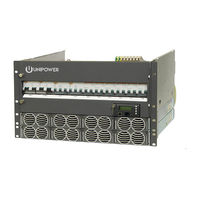
Unipower GDN.S.48.MS31 Instruction Manual (55 pages)
5U/6U 19” Rack Mount
Brand:
Unipower
| Category:
Power Supply
| Size: 6 MB
Table of Contents
Table of Contents
3
Chapter 1 About this Manual
6
Objectives
6
Audience
6
Document Key
6
Chapter 2 System Description
8
Overview
8
Figure 2-1 Power System Overview (6U System Shown)
8
Principal of Operation
9
Figure 2-2 Principal of Operation
9
System Parameters
10
System Components
12
System Controller
12
DC Distribution Unit
12
Rectifier Module
13
Figure 2-3 Guardian Rectifier
13
Rectifier Shelf
14
Figure 2-4 Guardian Rectifier Shelf
14
Chapter 3 System Safety
15
Safety Warnings and Guidelines
15
System Markings
15
Safety Recommendations
15
Installation Warning
16
Restricted Access Area Warnings
16
System Enclosure
16
Operating Temperature Warnings
16
Recommended Power Ratings
16
Electrical Safety Warnings
17
Grounding
18
Batteries
18
Lead Acid Batteries
18
In Case of an Accident
19
Caution
19
Storage and Transportation
19
Disposal
19
Handling Electrostatic Sensitive Devices
19
Traceability
19
Breakers
20
Hot Surfaces
20
Chapter 4 Installation Guide
21
Site Requirements
21
Unpacking
21
Tools
21
Cable Size
22
Table 4-1 Recommended Electrical Cable Sizes
22
Mounting in a Cabinet / Relay Rack
23
Figure 4-1 Mounting the Subrack (6U System Shown)
23
Removing the Covers (Optional)
24
Connecting Grounding Cable
24
Figure 4-2 Removing the Top Cover
24
AC Input Connection
25
Figure 4-3 Grounding Connection
25
Figure 4-4 AC Input Terminal Block (1-Phase)
26
Figure 4-5 AC Input Terminal Block (2-Phase)
26
Figure 4-6 AC Input Terminal Block (3-Phase)
26
DC Load Connection
28
Battery Cable and Connection
29
Battery Installation
30
Alarm and Signal Connections
31
Figure 4-11 ACX External Connection Board
32
Symmetry Connection
33
Figure 4-12 ACX Alarm Relay Board
33
Temperature Sensor Connection
34
Figure 4-13 2-Block Symmetry Measurement (for Illustration Only)
34
Figure 4-14 4-Block Symmetry Measurement (for Illustration Only)
34
Figure 4-15 Temperature Sensor Connection
35
Rectifier Installation
36
Figure 4-16 Rectifier Installation
36
Chapter 5 Commissioning
37
Commissioning Overview
37
Tools and Test Equipment
37
Tools List
37
Test Equipment
37
Preparation
37
Commissioning Procedure
38
Test of Output Voltage
39
Float Charge (U1)
39
Adjustment of Float Charge, U1
39
Boost Charging (U2) (if Applicable)
39
Table 5-1 Float/Boost Charge Voltages
39
Battery Supervision
40
Battery Test
40
Commissioning Record
41
Table 5-2 Commissioning Record
41
Chapter 6 Maintenance & Troubleshooting
42
Maintenance
42
Checking Terminal Connection
42
Other Requirements
42
Table 6-1 Connection Torque Setting Check
42
Troubleshooting
43
Chapter 7 Replacing Modules
47
Controller Replacement
47
Rectifier Replacement
47
Battery and Load Breakers Replacement
47
Surge Protection Device Replacement
48
Appendix A - Drawings
49
System Unit Layout
49
Installation Details - Connections
50
Block Diagram & Schematics
51
Detailed Dimensions
54
Advertisement
Advertisement
Related Products
Unipower Guardian Access
Unipower ARE Series
Unipower ARE130AC12F
Unipower ARE130AC16F
Unipower ARE130AC25F
Unipower ARE130AC35F
Unipower ARE130AC6F
Unipower ARE130CE12F
Unipower ARE130CE25F
Unipower ARE130CE35F
Unipower Categories
Power Supply
Power distribution unit
Inverter
Measuring Instruments
Battery Charger
More Unipower Manuals
Login
Sign In
OR
Sign in with Facebook
Sign in with Google
Upload manual
Upload from disk
Upload from URL