
Subscribe to Our Youtube Channel
Related Manuals for Novatech Bitronics M660

Summary of Contents for Novatech Bitronics M660
- Page 1 M660/M663/M661 Advanced Panel Meter/Transducer User Manual October 15, 2019 ML0042 Document Revision K © 2019 by Bitronics, LLC...
- Page 2 ML0042 October 15, 2019 Copyright 2019 Bitronics, LLC...
-
Page 3: Table Of Contents
TABLE OF CONTENTS 60 SERIES MANUAL SET ..........................6 VERSION HISTORY (ABRIDGED) ........................ 6 CERTIFICATION............................. 7 INSTALLATION AND MAINTENANCE ......................7 WARRANTY AND ASSISTANCE ........................7 AUTHORIZED REPRESENTATIVE IN THE EUROPEAN UNION ..............8 ... - Page 4 3.6 Optional Energy Pulse Outputs ......................40 4.0 OPERATION ............................43 4.1 Display ..............................43 4.1.1 Overview – Buttons Functions ......................55 4.1.2 Keypad Functions for Display Mode ....................56 4.1.3 Display Error Messages ......................... 57 ...
- Page 5 ML0042 October 15, 2019 Copyright 2019 Bitronics, LLC...
-
Page 6: Series Manual Set
60 SERIES MANUAL SET ML0042 M66x Family User Manual ML0036 50/60 Series DNP3 Protocol ML0037 50/60 Series Modbus Protocol ML0043 M66x IEC 61850 Protocol Manual ML0048 PowerPlex II and 60 Series EtherNet/IP Protocol Manual ML0049 M661P3 Pole Top User Manual VERSION HISTORY (ABRIDGED) V1.00 2014-07-14 Initial release... -
Page 7: Certification
CERTIFICATION Bitronics LLC certifies that the calibration of our products is based on measurements using equipment whose calibration is traceable to the United States National Institute of Standards Technology (NIST). INSTALLATION AND MAINTENANCE Bitronics LLC products are designed for ease of installation and maintenance. As with any product of this nature, installation and maintenance can present electrical hazards and should be performed only by properly trained and qualified personnel. -
Page 8: Authorized Representative In The European Union
AUTHORIZED REPRESENTATIVE IN THE EUROPEAN UNION NovaTech Europe BVBA Kontichsesteenweg 71 2630 Aartselaar Belgium T +32.3.458.0807 F +32.3.458.1817 info.europe@novatechweb.com COPYRIGHT NOTICE This manual is copyrighted and all rights are reserved. The distribution and sale of this manual is intended for the use of the original purchaser or his agents. This... -
Page 9: Safety Section
SAFETY SECTION This Safety Section should be read before commencing any work on the equipment. Health and safety The information in the Safety Section of the product documentation is intended to ensure that products are properly installed and handled in order to maintain them in a safe condition. - Page 10 If there is unlocked access to the equipment, care should be taken by all personnel to avoid electric shock or energy hazards. Voltage and current connections should be made using insulated crimp terminations to ensure that terminal block insulation requirements are maintained for safety. To ensure that wires are correctly terminated, the correct crimp terminal and tool for the wire size should be used.
-
Page 11: Warning: Emissions - Class A Device (En55011)
Fiber optic communication Where fiber optic communication devices are fitted, these should not be viewed directly. Optical power meters should be used to determine the operation or signal level of the device. WARNING: EMISSIONS – CLASS A DEVICE (EN55011) This is a Class A industrial device. Operation of this device in a residential area may cause harmful interference, which may require the user to take adequate measures. -
Page 13: Description & Specifications
1.0 DESCRIPTION & SPECIFICATIONS 1.1 Introduction The M66x family of advanced panel meters/transducers provides a range of measurement and communications capabilities for 3-phase metering. They offer an outstanding display (M660), superior communications flexibility and easy setup. The following Model M66x types are covered in this manual: M3 - Multifunction Advanced, 3-Phase 1.2 Features Full basic measurement set with optional demand and harmonic values... - Page 14 Burden: 5W max Overcurrent protection (Required) : Refer to section 2.4 AUX PWR (Universal – Hi Range Power Supply) - Power Supply Input (Auxiliary Voltage) – terminals L1(+) and L2(-) Installation Category/Overvoltage Category (Auxiliary Power Supply) – CAT II Nominal: 48-250V dc, 69-240V ac (50/60Hz) Operating Range: 37-300V dc, 55-275V ac (45-65Hz)
- Page 15 Input Signals – Measurement Inputs Configuration All Input Options 3 Inputs. 3 Phase Currents (IA, IB, IC). Current Nominal Input Option 1 1A ac Inputs Input Option 5 5A ac Input Option C 5A ac with split-core CTs Input Option T 5A ac Range Input Option 1...
- Page 16 Input Signals – Measurement Inputs Range 0 to 150V rms System Voltage Intended for use on nominal system voltages up to 208 V rms, phase-to-phase (120V rms, phase-to-neutral). Common Mode Reads to 400V peak, any input-to-case (ground) Input Voltage Impedance >12M ohms, input-to-case (ground) Voltage 2.5kV rms 1min, input-to-case (ground)
- Page 17 Accuracy Accuracies are specified at nominal Frequency and 25C, (unless otherwise noted). Unless noted, all values are true RMS and include Harmonics to the 31st (minimum). Voltage AC: Better than 0.1% of reading (20 to 150 V rms, input-to-case). (+/- 25ppm/DegC) Voltage Aux Only included with...
- Page 18 Relative Humidity 0-95% non-condensing Measurement Inputs CAT III (Distribution Level) Refer to definitions below. (VTs, CTs) Installation/Measurement Category Pollution Degree Pollution Degree 2 Refer to definitions below. Enclosure Protection Front Panel: IP 20, Rear: IP 20 (to IEC60529: 2001) When equipment is mounted in an appropriately rated protective enclosure to NEMA or IP protection classifications, as required for the installation.
- Page 19 Physical Connections Protective 10-32 Studs for connection with protective earth ground. Recommended Torque: 12 In-Lbs, Conductor 1.36 N-m Terminal Cable temperature rating: 85C minimum Current Internal Isolation - Current Input Option 1 or 5. 10-32 Studs for current inputs. Recommended (CT) Torque: 12 In-Lbs, 1.36 N-m Cable temperature rating: 85C minimum...
-
Page 20: Standards And Certifications
Definitions: Enclosure Category 2: Enclosures where no pressure difference relative to the surrounding air is present. Installation Category II (Overvoltage Category II) or CAT II: Equipment is intended for connection to the fixed installation of a building. The power supply to the electronic equipment is separated from other circuits, usually by a dedicated transformer for the mains power supply. - Page 21 Safety Requirements for Electrical Equipment for Measurement, Control, and Laboratory Use – Part 1: General Requirements UL61010-2-30, Edition 1 – Issue Date 2012/05/11 Safety Requirements for Electrical Equipment for Measurement, Control, and Laboratory Use – Part 2: Particular Requirements for Testing and Measuring Circuits CSA C22.2 No.
- Page 22 AC Powerline Conducted Emissions EN 55011: 2009 + A1: 2010 EN 55011: 2016 EN 61000-6-4: 2007 + A1:2011 (IEC date 2010 Group 1, Class A Frequency: 150 kHz – 30 MHz Conducted Emissions, Telecommunication port (Ethernet port) EN 55022: 2010 + AC: 2011 EN 55032: 2012 + AC: 2013 EN 55032: 2015 + AC: 2016-07 Group 1, Class A...
- Page 23 Power Frequency Magnetic Fields EN 61000-4-8: 2010 Amplitude: 30A/m Frequency: 50 and 60 Hz AC Supply Voltage Dips and Short Interruptions EN 61000-4-11: 2004 Surge Withstand Capability Test For Protective Relays and Relay Systems ANSI/IEEE C37.90.1: 2002 (2.5 kV oscillatory wave and 4 kV EFT) ML0044B October 15, 2019 Copyright 2019 Bitronics, LLC...
-
Page 24: Physical Construction & Mounting
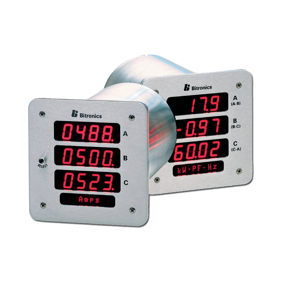
2.0 PHYSICAL CONSTRUCTION & MOUNTING The M66x are packaged in rugged aluminum case specifically designed to meet the harsh conditions found in utility and industrial applications. The Front panel view for the M660 and M663 (19” rack mount version) and the mounting plate view for the M661 are shown in Figure 1. - Page 25 Figure 2A - Mounting and Overall Dimensions M660 and M661 (back panel may vary as a result of options ordered) ML0044B October 15, 2019 Copyright 2019 Bitronics, LLC...
- Page 26 Figure 2B - Mounting and Overall Dimensions M653 (rack mount above, panel mount below; back panel may vary due to options ordered) ML0044B October 15, 2019 Copyright 2019 Bitronics, LLC...
-
Page 27: Installation
2.1 Installation WARNING - INSTALLATION AND MAINTENANCE SHOULD ONLY BE PERFORMED BY PROPERLY TRAINED OR QUALIFIED PERSONNEL. 2.2 Initial Inspection Bitronics instruments are carefully checked and "burned in" at the factory before shipment. Damage can occur however, so please check the instrument for shipping damage as it is unpacked. -
Page 28: Cleaning
Several instruments may be mounted on a 19" Rack panel if desired. Three units will fit side by side on a standard 5.25" high panel. Figure 2 indicates the dimensions of the panel hole cutout. Leave adequate space surrounding the instrument when determining mounting arrangements. -
Page 29: Back Panel & Wiring
3.0 BACK PANEL & WIRING The rear view of the M66x is shown in figure 3A with the fiber option port shown, however, it is also possible to have a meter with a serial port or without this option port. See Appendix A1 for detailed wiring diagrams covering the CT/VT measurement inputs. -
Page 30: Auxiliary Power
3.1 Auxiliary Power The M66x meters are powered by connections to L1(+) and L2(-). A Blue LED Power (PWR) indicator is provided on the rear panel to indicate that the unit is powered ON. It is located on the right of the rear panel. There is an option that allows the voltage across the Auxiliary Power input voltage across terminals L1(+) and L2(-) to be monitored. -
Page 31: Vt Inputs - Va, Vb, Vc, Vn (See Appendix A1 And Section 1.3)
3.2 VT Inputs – VA, VB, VC, VN (See Appendix A1 and Section 1.3) The M66x meter voltage (VT) signal inputs are connected to terminals 3-6 (see Appendix A1 for specific wiring configurations). Voltage signals are measured using a 12M ohm resistor divider with a continuous voltage rating of 7kV. This ideal impedance provides a low burden load for the VT circuits supplying the signals. -
Page 32: Ethernet
driver. 12 inch-pounds (1.36 N-m) is recommended, MAXIMUM torque is 15 inch- pounds (1.69 N-m). . 3.4 Ethernet The M66x Ethernet port meets or exceeds all requirements of ANSI/IEEE Std 802.3 (IEC 8802-3:2000) and additionally meets the requirements of part 8-1 TCP/IP T- profile for physical layer 1 (Ethernet copper interface). - Page 33 not already in use on your network. You may also want to check with your network administrator to make sure the IP address you plan on using is available to use on your network. After entering the Network addresses exit out of the menu, and when prompted to save the new configuration settings, press the button directly under the SAVE prompt identified as “Y”...
-
Page 34: Indicators - Ethernet (Act) & Fiber Leds
<ms> := period between polls (100ms) <mac-spec> := <6ByteMac> | <[3-5]ByteMac> | <macRangeName> <6ByteMac> := xx:xx:xx:xx:xx:xx - <cnt> can specify a range to scan <5ByteMac> := xx:xx:xx:xx:xx - default <cnt> is 256 <3ByteMac> := xx:xx:xx - default <cnt> is 16,777,216 <macRangeName>... - Page 35 availability of firmware upgrades. In cases such as this, it is desirable to support a mechanism for new firmware to be installed remotely. The ability to upgrade Firmware is done over the Ethernet port. The M66X family utilizes a page in the Web Server interface to upload and install new firmware.
-
Page 36: Optional Serial Port
Figure 4 – Bitronics M66X Firmware Upload Page Once the Firmware Upload page is visible, use the Browse button to locate the firmware image on your computer. Next use the Submit button to initiate the file transfer and installation process. The instrument must be rebooted to make the new firmware active. -
Page 37: Rs232/485 Connections
The M66x has an optional serial port that is user configurable for RS232 or RS485, and support baud rates up to 115200. See section 4.4 for screen shot showing web configuration for serial port. For meters with a display, the serial port can also be setup via the front display buttons (Setup menu - Serial).The RS-232 drivers support full and half duplex modes. - Page 38 Figure 5 - Typical RS-485 Cable Wiring ML0042 October 15, 2019 Copyright 2019 Bitronics, LLC...
- Page 39 Figure 6 – RS-232 Cable Wiring Diagram ML0042 October 15, 2019 Copyright 2019 Bitronics, LLC...
-
Page 40: Optional Energy Pulse Outputs
3.6 Optional Energy Pulse Outputs There is an option for 4 KYZ pulse outputs with common ground. Pulse output meters are consumption monitoring devices. A pulse output power meter will indicate the number of kWhs used by the system load. Historically, rotating meters could report their power information remotely, using a pair of contact closures attached to a KYZ line. - Page 41 Figure 7 – Pulse Output Connections KYZ configuration in the 60 Series is achieved by navigating to the Settings / Input screen of the instrument’s webserver. When the 4 digital KYZ option is ordered, the positive and negative KWHr and KVarHr can be assigned to any of the four outputs in whatever order is desired.
- Page 42 Energy per Pulse (EPP) The EPP parameter has a range of 10 to 10 with units of KWhr / kVARhr. The default value of EPP is 10 KWhr / kVARhr primary engineering units. The time between rising edges defines the length of the energy pulse as shown below.
-
Page 43: Operation
4.0 OPERATION 4.1 Display The M660 meters can display several per-phase and total quantities for the circuit being monitored. In order to make all quantities available, the display scrolls from quantity to quantity approximately every 5 seconds. The quantities are refreshed once a second. - Page 44 INSTANTANEOUS DISPLAY SCREENS Format Quantity 00000 Phase A Amperes 00000 Phase B Amperes 00000 Phase C Amperes AmpsΦ 00000 Residual Amperes Unused Unused AmpsR 00000 Phase A Volts 00000 Phase B Volts 00000 Phase C Volts xVolts 00000 Phase A-B Volts 00000 Phase B-C Volts...
- Page 45 00000 Phase A VAs 00000 Phase B VAs 00000 Phase C VAs xVA Φ 00000 Phase A PF 00000 Phase B PF 00000 Phase C PF PF Φ 10. 00000 Total VAs 00000 3Φ PF Unused xVAsPF 11. 00.000 Frequency ...
- Page 46 16. 000.00 VA hours (Most significant half) 000.00 VA hours ( Least significant half) Unused kVAh 17. 00000 Watt hours Net (Most significant half) 00000 Watt hours Net (Least significant half) Unused kWh NET 18. 00000 Total Watts 00000 3Φ...
- Page 47 DEMAND DISPLAY SCREENS Format Quantity 19. 000.00 Phase A Amps Demand 000.00 Phase B Amps Demand 000.00 Phase C Amps Demand Amps Dmd 20. 00000 Phase A Maximum Amperes Demand 00000 Phase B Maximum Amperes Demand 00000 Phase C Maximum Amperes Demand Amps MAX 21.
- Page 48 27. 00000 Phase A-B Minimum Volts Demand 00000 Phase B-C Minimum Volts Demand 00000 Phase C-A Minimum Volts Demand xV MIN 28. 00000 Total Maximum Watt Demand 00000 Total Watts (Also on Screen 7) 00000 Total Minimum Watt Demand xW 29.
- Page 49 HARMONIC SUMMARY DISPLAY SCREENS Format Quantity 31. 00000 Phase A Fundamental Amperes 00000 Phase B Fundamental Amperes 00000 Phase C Fundamental Amperes Fnd Amps 32. 00000 Fundamental Residual Amperes Unused Unused FndN Amps 33. 00000 Phase A Fundamental Volts 00000 Phase B Fundamental Volts 00000...
- Page 50 38. 00.000 K-Factor Phase A (Current) 00.000 K-Factor Phase B (Current) 00.000 K-Factor Phase C (Current) K-Factor - WYE meters only x - indicates blank, (k)ilo, (M)ega, or (G)iga ML0042 October 15, 2019 Copyright 2019 Bitronics, LLC...
- Page 51 HARMONIC SUMMARY DISPLAY SCREENS (Cont’d) Format Quantity 39. 0.0000 Phase A Displacement PF 0.0000 Phase B Displacement PF 0.0000 Phase C Displacement PF DispPF Φ 40. 00000 3Φ Displacement PF Unused Unused DispPF T 41. 000.00 Phase A Fundamental Demand Amps 000.00 Phase B Fundamental Demand Amps 000.00...
- Page 52 46. 000.00 Phase A Minimum Average Watts 000.00 Phase B Minimum Average Watts 000.00 Phase C Minimum Average Watts xW Min 47. 000.00 Phase A Average VARs 000.00 Phase B Average VARs 000.00 Phase C Average VARs xVAR Avg 48. 000.00 Phase A Maximum Average VARs 000.00 Phase B Maximum Average VARs...
- Page 53 53. 00000 Phase A Secondary Volts 00000 Phase B Secondary Volts 00000 Phase C Secondary Volts SecVolts 54. 00000 Phase A-B Secondary Volts 00000 Phase B-C Secondary Volts 00000 Phase C-A Secondary Volts SecVolts 55. 000.00 Auxiliary Voltage Unused ...
- Page 54 The screens that are displayed in the scrolling mode can be programmed (ENABLED/DISABLED) by the user. This programming can be done by using the front panel buttons of the device or through the web server. Enable/Disable Display Mode Screens via the front buttons on Display: The Screens can be enabled or disabled (refer to Section 5.5) via the front display buttons by entering the setup mode section and going to the Screen Enable menu (1.6, Scrn Ena).
-
Page 55: Overview - Buttons Functions
4.1.1 Overview – Buttons Functions Figure 8 – Button functions for Display Mode Figure 9 – Button functions in Set-up Mode ML0042 October 15, 2019 Copyright 2019 Bitronics, LLC... -
Page 56: Keypad Functions For Display Mode
4.1.2 Keypad Functions for Display Mode Measurements screens may be stepped through manually by pushing the up and down arrow keys. Pushing the Toggle (Exit) key turns the scroll function off and on. When the scroll function is activated, the measurement screens will automatically step through the user- defined screens. -
Page 57: Display Error Messages
Button Display Mode Function Setup Mode Function Combination Home Designate the displayed (Enter) and Toggle screen as “Home Screen” (Exit) keys Resets are found in setup menu 4.1.3 Display Error Messages Error messages from self test are shown on the display (M660). The table below summarizes the errors and the messages displayed: SELF TEST RESULT SUMMARY FOR 60 SERIES DEVICES Fault... -
Page 58: Functional Description
5.0 FUNCTIONAL DESCRIPTION 5.1 Configuration Setup of the M66X meters is most easily performed using the web interface via the Ethernet service port. Basic configuration can also be handled from the front display by entering the setup mode. 5.2 HTML Web Server The M66X incorporates an internet-compatible HTML web page. -
Page 59: Using The M66X With A Bitronics Analog Output Converter
Lock Menu & Resets - Prevents access to the front panel configuration menu as well as reset and home screen shortcuts (see sec 4.1.2). Lock Menu only - Prevents access to the front panel configuration menu. Reset and home screen shortcuts are allowed. If a front panel display action covered under one of the Front Panel Configuration Lock options is attempted while the lock is enabled, the message 'Locked' will be briefly displayed on the front panel alphanumeric display. - Page 60 Optimal Resolution and the Bitronics Legacy register set. When using AOCs that communicate via Modbus (NAO8101 and NAO8102), the M66X serial port must be set for an RxD to TxD Delay of 10ms for proper operation. Serial port and connection information is shown below.
-
Page 61: Navigating The M660'S Setup Menu From The Front Panel
5.5 Navigating the M660’s setup menu from the front panel ML0042 October 15, 2019 Copyright 2019 Bitronics, LLC... - Page 62 SCRN ENA [Amps Φ] Amps A, B C Amps R] Amps Reidual [kVolts Φ] Volts AN, BN, CN [kVolts] Volts AB, BC, C [Watts Φ] WattsA, B,C [kVARΦ] VARs A, B, C [kW∙kVAR] Total Watts∙ Total VARs [kVAΦ] VAs A, B, C [PFΦ] Power Factor A, , C [kVA∙PF] Total VAs ∙ 3Φ PF [Hz] Frequeny [kWh] kWatt‐Hour Normal(+) [‐kWh] kWatt‐Hours Reverse(‐) [+kVARh] kVAR‐Hous Laggin(+) [‐kARh] kVA‐Hours Leading(‐) [kVAh] kVA‐Hours [kWhNE] kWatt‐Hours Net [kW∙PF∙Hz] Total Watts ∙ 3Φ PF ∙ Frequency [AmpsDmd] Demand Amps A,B,C [AmpsDmd axDmand Amps A,B,C ...
- Page 63 ML0042 October 15, 2019 Copyright 2019 Bitronics, LLC...
- Page 64 ML0042 October 15, 2019 Copyright 2019 Bitronics, LLC...
- Page 65 How to Enter an Integer: Increment highlighted digit by 1. ENTER Highlight Previous/Next digit. Exit to menu EXIT How to Enter a Floating Point Number: Increment highlighted digit by 1. ENTER Shifts decimal point one place to right. Decimal moves to left‐most digit when right‐most digit is passed. Highlight Next digit. Highlights left‐most digit when right‐ most digit is passed. Exit to menu EXIT How to Enter an IP address: Increment highlighted digit by 1. ENTER Highlight Previous/Next digit. Numbers scroll left and right to follow highlighted digit. Exit to Network menu EXIT - 65 - ML0042 May 17, 2019 Copyright 2019 Bitronics, LLC...
-
Page 66: Performing Set-Up Through The Web
5.6 Performing set-up through the web page interface This section will assume you are able to use the factory default IP address of 192.168.0.171 to connect to the web page using an HTML web server. If this is not the case you may need to refer to section 3.5.1 (Network settings) and the previous section (Navigating the M66X’s setup menu from the Front panel) to change your network configuration settings. - Page 67 Data page: Three views – Instantaneous, Demands and Trend Log - 67 - ML0042 October 15, 2019 Copyright 2019 Bitronics, LLC...
- Page 68 The data page for trend recording gives information about the trend record, but also provides for retrieving it, or part of it via start and end times, in .csv format. Resets page: From this page select the quantity to be reset and click apply. Optionally, Energy values can be reset to specific non-zero values by entering the desired reset value in the appropriate field as a whole number and clicking Apply.
- Page 69 Settings page: Click on one of the settings categories (Identity, Input, Network, Protocol, etc.) to be taken to the next page. - 69 - ML0042 October 15, 2019 Copyright 2019 Bitronics, LLC...
- Page 70 Settings Page Selections: From the Settings page screen you can select one of the following selections: Identity– This page allows the user to enter information that is necessary to identify the meter. It gives an identity to a particular M66X. Each M66X should have different information entered for its identity.
- Page 71 Screen shots showing the selections to be made for each of the above selections follow on the next few pages. Default values are shown where applicable. M66X configuration changes require the unit to be rebooted. Configuration settings for the M66X are stored in flash memory. Identity: - 71 - ML0042...
- Page 72 Input: - 72 - ML0042 October 15, 2019 Copyright 2019 Bitronics, LLC...
- Page 73 Network: Serial Port (if option ordered): - 73 - ML0042 October 15, 2019 Copyright 2019 Bitronics, LLC...
- Page 74 Protocol Selection: Modbus and DNP3 First select between Modbus or DNP3. You will then select Optimal Resolution (default) or Primary Units. Next you will choose a session. Under Type, there will be 4 different selections for Modbus and 3 for DNP3. Under Modbus the options are Disabled, TCP, ASCII, or RTU.
- Page 75 DNP TCP Advanced - 75 - ML0042 October 15, 2019 Copyright 2019 Bitronics, LLC...
- Page 76 Modbus RTU - 76 - ML0042 October 15, 2019 Copyright 2019 Bitronics, LLC...
- Page 77 Modbus TCP - 77 - ML0042 October 15, 2019 Copyright 2019 Bitronics, LLC...
- Page 78 IEC61850: IED Capability Description (ICD) file: The 60 Series ICD file is an IEC61850 Substation Configuration Language (SCL) file which contains the IEC61850 'capability' description of the 60 Series IED. It is used by the IEC61850 IED Configurator tool to perform an IEC61850 configuration. The ICD file is stored on the M66x IED in flash memory.
- Page 79 The built-in Web browser in the 60 Series IED is then used to upload the configuration file from the PC and reboot the M66x device. The CID file is stored in flash memory of the M66x device after reboot and will remain the active configuration until a new configuration is uploaded or the user overwrites the configuration with a built-in demo configuration.
- Page 80 Screen Enable (M660): - 80 - ML0042 October 15, 2019 Copyright 2019 Bitronics, LLC...
- Page 81 The M663 is similar but adds the ability to select what is to be displayed on the left and right displays. Custom Display Screen Settings (M660):Two Sections – Build/Edit and Summary The Custom Display Screen Configuration page contains two sections: the Build/Edit panel and the Summary panel.
- Page 82 Summary panel Screens are saved to IED once the “Apply” button has been clicked. A row (screen) from the summary table can be selected for viewing, editing or deleting by clicking its radio button. The order of the screens can be changed by selecting a screen from the list and clicking on the up or down arrows.
- Page 83 - 83 - ML0042 October 15, 2019 Copyright 2019 Bitronics, LLC...
- Page 84 Load/Store Device Settings: - 84 - ML0042 October 15, 2019 Copyright 2019 Bitronics, LLC...
- Page 85 Password Security Settings: Firmware Upload: - 85 - ML0042 October 15, 2019 Copyright 2019 Bitronics, LLC...
- Page 86 Trend Recorder: The trend recorder allows up to 65 of the 200+ available measurements to be recorded at intervals of once per second or slower. The maximum is 10 measurements at intervals of 30x/sec or 60x/sec (1x every other cycle or 1x per cycle).
- Page 87 - 87 - ML0042 October 15, 2019 Copyright 2019 Bitronics, LLC...
- Page 88 Status Page: The IED Status page shows the status of the IEC61850 communications interface and the health status. The IEC61850 status states are Operational and Not Running. When the 61850 stack is not running, the reason is displayed. When the 61850 stack is not able to start due to an error, the startup log is displayed for additional detail.
- Page 89 - 89 - ML0042 October 15, 2019 Copyright 2019 Bitronics, LLC...
- Page 90 Note that if EtherNet/IP option was purchased, there will be a Status page for that. Please refer to section 4 of the PowerPlex II and 60 Series EtherNet/IP Protocol Manual, ML0048 for more information. Contact Page: - 90 - ML0042 October 15, 2019 Copyright 2019 Bitronics, LLC...
-
Page 91: Measurements
6.0 MEASUREMENTS Basic measurement quantities are calculated and updated every 100 ms. These quantities include RMS Amperes and RMS Volts, Watts, VARs, VAs, Power Factor, all harmonic-based measurements (such as fundamental-only quantities), Energy, and Frequency, and Phase Angle. Note: For all of the following measurements, it is important to keep in mind that the specific protocol used to access the data may affect the data that is available, or the format of that data. -
Page 92: Voltage Channels
6.3 Voltage Channels All voltage inputs are measured relative to a common reference level (essentially panel ground). See Appendix 1 for input connection information. Common mode signals can be removed by signal processing algorithms, instead of the more traditional difference amplifier approach. This greatly simplifies the external analog circuitry, increases the accuracy, and allows measurement of the Neutral-to-Ground voltage at the panel. -
Page 93: Geometric Va Calculations
together. This represents the dot product of the voltage and current vectors, or the true Watts. The per-element VAs are calculated from the product of the per-element Volts and Amps. The per-element VARs are calculated from fundamental VARs. In any connection type, the Total Watts and Total VARs is the arithmetic sum of the per-element Watts and VARs. - Page 94 Figure 10 - Sign Conventions for Power Measurements (P is Power, Q is VARS and S is VA) - 94 - ML0042 October 15, 2019 Copyright 2019 Bitronics, LLC...
-
Page 95: Compensated Watts And Vars (Line And Transformer Loss Compensation)
6.7 Compensated Watts and VARs (Line and Transformer Loss Compensation) The total Watt and Var losses can be calculated using five user entered parameters and measured current and voltage values. These losses are added or subtracted to/from the measured Total Watts and Total Vars when accumulating Energy. ... -
Page 96: Energy
A detailed application note on loss compensation in the 50 and 60 Series can be found in the documentation library of the Novatech website, www.novatechweb.com. 6.8 Energy Separate values are maintained for both positive and negative Watt-hours, positive and negative VAR-hours, and VA-hours, for each feeder. -
Page 97: Frequency
6.9 Frequency The M66X monitors the change in Phase Angle per unit time using the Phase Angle measurement for the fundamental generated by the FFT. The System Frequency is the frequency of the input used for synchronizing the sampling rate. 6.10 Demand Measurements The traditional thermal demand meter displays a value that represents the logarithmic response of a heating element in the instrument driven by the applied signal. -
Page 98: Ampere And Fundamental Ampere Demand
6.10.1 Ampere and Fundamental Ampere Demand Present Ampere Demands are calculated via the instantaneous measurement data used to calculate the per-phase Amperes. Upon power-up, all Present Ampere Demands are reset to zero. Maximum Ampere Demands are initialized to the maximum values recalled from non-volatile memory. Upon Ampere Demand Reset, all per-phase Present and Maximum Ampere Demands are set to zero. -
Page 99: Demand Interval
6.10.5 Demand Interval The M66X uses 900 seconds (15 minutes) as the default demand interval for current. The default for average volts and average power measurements is 60 seconds. Three separate, independent demand intervals may be set for current, voltage, and power. The range of demand intervals is 10 to 9999 seconds. -
Page 100: Fundamental Current
100 Amp load with 30% Distortion. By using TDD, these same two loads would exhibit 0.3% TDD for the 1 Amp load and 30% TDD for the 100 Amp load (if the Denominator was set at 100 Amps). In the M66X, Current Demand Distortion is implemented using Equation 3. -
Page 101: K-Factor
Fundamental Volts and Amps can be used in conjunction to obtain Fundamental VAs, and when used with Displacement Power Factor can yield Fundamental Watts and Fundamental VARs. 6.11.5 K-Factor K-Factor is a measure of the heating effects on transformers, and it is defined in ANSI/IEEE C57.110- ... -
Page 102: Heartbeat And Health Check
6.12 Heartbeat and Health Check M66x provide a Heartbeat State Counter Register that allows the user to determine the time between successive polls. This counter will increment by the number of milliseconds that have elapsed since the last time the data was updated. Another use of this register is as a visual indicator that the data is changing;... -
Page 103: List Of Available Measurements & Settings
6.13 List of Available Measurements & Settings Available Measurements Amps A, B, C, Residual Heartbeat Average 3-phase Amps K-factor Amps A Average 3-Phase Volts (L-L, L-N) K-factor Amps B Average Volts AN, BN, CN, AB, BC, CA K-factor Amps C Average (Max.) Volts AN, BN, CN, AB, BC, K-factor Amps Residual Average (Min.) Volts AN, BN, CN, AB, BC, CA... -
Page 104: Instantaneous Measurement Principles
6.15 Instantaneous Measurement Principles The M66X measures all signals at an effective rate of 64 samples/cycle, accommodating fundamental signal frequencies from 45 to 65Hz depending on model. Samples of all bus signals are taken using a 16-Bit A/D converter, effectively creating 64 "snapshots"... -
Page 105: Appendix
APPENDIX A1 CT/VT Connection Diagrams Please note that there is an option on the Settings/Input page to invert the CT Polarity (see screen shot clip below). This option is the equivalent of swapping the connections in the connection diagrams below at the HI and LO terminals for each CT input, that is, swapping 7 and 10, 8 and 11, 9 and 12. - Page 106 Figure 11 - Signal Connections – M66X - 106 - ML0042 October 15, 2019 Copyright 2019 Bitronics, LLC...
- Page 107 Figure 11 - Signal Connections – M66X - 107 - ML0042 October 15, 2019 Copyright 2019 Bitronics, LLC...
- Page 108 - 108 - ML0042 October 15, 2019 Copyright 2019 Bitronics, LLC...
-
Page 109: A2 Ethernet Troubleshooting
A2 Ethernet Troubleshooting If the Link LED fails to illuminate, this is an indication that there is trouble with the connection and communication will not proceed without solving the problem. If a copper connection is used between the M66X and the hub/switch, check the following items: Verify that the connectors are fully engaged on each end. -
Page 110: A3 Display Screens - Visual Representations (M660)
A3 Display Screens – Visual Representations (M660) - 110 - ML0042 October 15, 2019 Copyright 2019 Bitronics, LLC... - Page 111 - 111 - ML0042 October 15, 2019 Copyright 2019 Bitronics, LLC...
- Page 112 - 112 - ML0042 October 15, 2019 Copyright 2019 Bitronics, LLC...
- Page 113 - 113 - ML0042 October 15, 2019 Copyright 2019 Bitronics, LLC...
- Page 114 - 114 - ML0042 October 15, 2019 Copyright 2019 Bitronics, LLC...
- Page 115 - 115 - ML0042 October 15, 2019 Copyright 2019 Bitronics, LLC...
- Page 116 - 116 - ML0042 October 15, 2019 Copyright 2019 Bitronics, LLC...
- Page 117 - 117 - ML0042 October 15, 2019 Copyright 2019 Bitronics, LLC...
- Page 118 - 118 - ML0042 October 15, 2019 Copyright 2019 Bitronics, LLC...
- Page 119 - 119 - ML0042 October 15, 2019 Copyright 2019 Bitronics, LLC...
- Page 120 - 120 - ML0042 October 15, 2019 Copyright 2019 Bitronics, LLC...
- Page 121 - 121 - ML0042 October 15, 2019 Copyright 2019 Bitronics, LLC...
- Page 122 - 122 - ML0042 October 15, 2019 Copyright 2019 Bitronics, LLC...
- Page 123 - 123 - ML0042 October 15, 2019 Copyright 2019 Bitronics, LLC...
- Page 124 - 124 - ML0042 October 15, 2019 Copyright 2019 Bitronics, LLC...
- Page 125 Revision Date Changes 1/16/2015 Original Issue E. DeMicco 2/17/15 Firmware update, new screen shots, E. DeMicco changes for configurable TCP keepalive time setting, status tab to web UI, IEC61850 enable/disable control 3/17/15 Firmware update for support of Edition 2 E. DeMicco and 100Mb fiber.
- Page 126 - 126 - ML0042 May 17, 2019 Copyright 2019 Bitronics, LLC...
- Page 127 Bitronics, LLC 261 Brodhead Road,Bethlehem, PA. 18017 (610) 997-5100 Fax (610) 997-5450 www.novatechweb.com /bitronics...
Need help?
Do you have a question about the Bitronics M660 and is the answer not in the manual?
Questions and answers