
Related Manuals for Novatech Bitronics PowerPlex II

Summary of Contents for Novatech Bitronics PowerPlex II
- Page 1 PowerPlex II Synchronizing Ethernet Transducer and Display User Manual December 1, 2017 ML0044B Document Revision H © 2017 by Bitronics, LLC...
- Page 2 ML0044B December 1, 2017 Copyright 2017 Bitronics, LLC...
-
Page 3: Table Of Contents
TABLE OF CONTENTS POWERPLEX II MANUAL SET ......................... 6 VERSION HISTORY (ABRIDGED) ......................6 CERTIFICATION............................7 INSTALLATION AND MAINTENANCE ....................7 WARRANTY AND ASSISTANCE ......................7 AUTHORIZED REPRESENTATIVE IN THE EUROPEAN UNION ............8 ... - Page 4 3.5.1 RS485 Connections (Extended Chassis Only) ................ 41 3.6 Optional Display Port (option includes IRIG-B and Energy Pulse LED) ........... 42 3.6.1 Display Screens (Optional Display) ..................44 3.6.2 Overview – Buttons Functions (Optional Display) ..............46 ...
- Page 5 A5 PowerPlex II Standard Display Screens – Visual Representations PPXIITD ........ 117 ML0044B December 1, 2017 Copyright 2017 Bitronics, LLC...
-
Page 6: Powerplex Ii Manual Set
POWERPLEX II MANUAL SET ML0044B PowerPlex II User Manual ML0045 PowerPlex II DNP3 Protocol ML0046 PowerPlex II Modbus Protocol ML0043 60 Series IEC 61850 Protocol VERSION HISTORY (ABRIDGED) V1.00.0 2014-07-29 Initial release V1.30.0 2014-10-22 Minor feature upgrades and bug fixes V2.06.0 2015-05-21 Minor feature upgrades V2.12.0... -
Page 7: Certification
CERTIFICATION Bitronics LLC certifies that the calibration of our products is based on measurements using equipment whose calibration is traceable to the United States National Institute of Standards Technology (NIST). INSTALLATION AND MAINTENANCE Bitronics LLC products are designed for ease of installation and maintenance. As with any product of this nature, installation and maintenance can present electrical hazards and should be performed only by properly trained and qualified personnel. -
Page 8: Authorized Representative In The European Union
AUTHORIZED REPRESENTATIVE IN THE EUROPEAN UNION NovaTech Europe BVBA Kontichsesteenweg 71 2630 Aartselaar Belgium T +32.3.458.0807 F +32.3.458.1817 info.europe@novatechweb.com COPYRIGHT NOTICE This manual is copyrighted and all rights are reserved. The distribution and sale of this manual is intended for the use of the original purchaser or his agents. This... -
Page 9: Safety Section
SAFETY SECTION This Safety Section should be read before commencing any work on the equipment. Health and safety The information in the Safety Section of the product documentation is intended to ensure that products are properly installed and handled in order to maintain them in a safe condition. - Page 10 If there is unlocked access to the equipment, care should be taken by all personnel to avoid electric shock or energy hazards. Voltage and current connections should be made using insulated crimp terminations to ensure that terminal block insulation requirements are maintained for safety. To ensure that wires are correctly terminated, the correct crimp terminal and tool for the wire size should be used.
-
Page 11: Warning: Emissions - Class A Device (En55011)
Fiber optic communication Where fiber optic communication devices are fitted, these should not be viewed directly. Optical power meters should be used to determine the operation or signal level of the device. WARNING: EMISSIONS – CLASS A DEVICE (EN55011) This is a Class A industrial device. Operation of this device in a residential area may cause harmful interference, which may require the user to take adequate measures. -
Page 13: Description & Specifications
1.0 DESCRIPTION & SPECIFICATIONS 1.1 Introduction The PowerPlex II (PPX II) is a synchronizing Ethernet transducer with two sets of three-phase voltages and 1-cycle measurement update speeds. It offers superior communications flexibility and easy setup. The following Model number of the product named PowerPlex II (PPX II) is covered in this manual: MTWDN7C –... - Page 14 AUX PWR (Universal – Hi Range Power Supply) - Power Supply Input (Auxiliary Voltage) – terminals L1(+) and L2(-) Installation Category/Overvoltage Category (Auxiliary Power Supply) – CAT II Nominal: 48-250V dc, 69-240V ac (50/60Hz) Operating Range: 37-300V dc, 55-275V ac (45-65Hz) Burden: 8W max, 24VA max Overcurrent protection (Required) : Refer to section 2.4...
- Page 15 Input Signals – Measurement Inputs CT Current Configuration 3 Inputs. 3 Phase Currents (IA, IB, IC). Inputs Nominal 5A ac Range 0 to 10A rms continuous at all rated temperatures Withstand Withstands 30A ac continuous, Under fault condition, can withstand 400Aac for 2 seconds Isolation 2500V ac, minimum.
- Page 16 Accuracy Accuracies are specified at nominal Frequency and 25C, (unless otherwise noted). Unless noted, all values are true RMS and include Harmonics to the 31st (minimum). Voltage AC: Better than 0.1% of reading (20 to 600V rms, input-to-case). (+/- 25ppm/DegC) Current Better than 0.1% of reading +/- 100uA (>0.5A to 10.0A, -20C to 70C) Better than 0.1% of reading +/- 250uA (0.05A to 0.5A, -20C to 70C)
- Page 17 Pollution Degree Pollution Degree 2 Refer to definitions below (at the end of this section). Enclosure Protection IP20 to IEC60529:2001 (to IEC60529: 2001) When equipment is mounted in an appropriately rated protective enclosure to NEMA or IP Applies to PPX II and protection classifications, as required for the installation.
- Page 18 Physical Connections Protective A #8-32 screw terminal is provided on the AUX PWR terminal block for connection with Conductor protective earth ground. Recommended Torque: 9 In-Lbs, 1.02 N-m Terminal Cable temperature rating: 85C minimum Current 10-32 Studs for current inputs. Recommended Torque: 12 In-Lbs, 1.36 N-m (CT) Cable temperature rating: 85C minimum Voltage...
- Page 19 Weight PowerPlex II: 2.3 lbs (1.04 kg) standard chassis; 3.5 lbs (1.59 kg) in extended chassis (with optional I/O (typical) and serial port) PPXIITD Tethered Display (Optional Accessory): 0.65 lbs (0.30 kg) Size PowerPlex II (Figure 2) Standard Chassis: 5.28"H x 5.60"W x 5.63"D – overall depth including handle is 5.75”D (134mm H x 142mm W x 143mm D –...
-
Page 20: Digital I/O (Optional) - Extended Chassis Only
Definitions: Enclosure Category 2: Enclosures where no pressure difference relative to the surrounding air is present. Measurement/Installation Category III (Overvoltage Category III) or CAT III: Distribution Level, fixed installation, with smaller transient overvoltages than those at the primary supply level, overhead lines, cable systems, etc. Pollution: Any degree of foreign matter, solid, liquid, or gaseous that can result in a reduction of electric strength or surface resistivity of the insulation. -
Page 21: Outputs
1.4.2 Outputs 4 outputs, 3 Normally Open (NO), 1 isolated, can be wired for Normally Closed (NC) or Normally Open (NO) operation for energized or de-energized condition. Output terminals have internal 510V clamp. Channels 1-3 share a common return, however, channel 4 has an independent return. - Page 22 Figure 1 – Simplified Circuitry for Input and Output Options ML0044B December 1, 2017 Copyright 2016 Bitronics, LLC...
-
Page 23: Standards And Certifications
Figure 2 - Wiring Terminal Assignments for Input and Output Options 1.5 Standards and Certifications 1.5.1 Revenue The PowerPlex II exceeds the accuracy requirements of ANSI C12.20 and IEC 62053- Type Nominal Current Certification MTWDN7C ANSI C12.20, 0.2CA IEC 62053-22, 0,2S IEC 62053-23, 0,2S (Reactive) The PowerPlex II was tested for compliance with the accuracy portions of the standards only. -
Page 24: Environment
1.6 Environment UL/CSA Listed, File Number E164178 (applies to standard chassis, does not apply to extended chassis with I/O and serial port) UL61010-1, Edition 3, Issue Date 2012/05/11 Safety Requirements for Electrical Equipment for Measurement, Control, and Laboratory Use – Part 1: General Requirements UL61010-2-30, Edition 1 –... - Page 25 Radiated Emissions Electric Field Strength EN 55011: 2009 + A1: 2010 EN 55011: 2016 EN 61000-6-4: 2007 + A1:2011 (IEC date 2010) Group 1, Class A Frequency: 30 - 1000 MHz AC Powerline Conducted Emissions (Applicable on VT inputs - Bus1/ Bus 2 and AUX PWR (Universal Hi Range AC/DC Power supply) EN 55011: 2009 + A1: 2010 EN 55011: 2016...
- Page 26 Electrical Fast Transient / Burst Immunity (Including optional display, display port and IRIG-B port) EN 61000-4-4: 2012 (supersedes EN 61000-4-4: 2004 + A1:2010) Burst Frequency: 5 kHz Amplitude, Signal Ports (VTs): ± 2 KV (Severity Level 3) Amplitude Signal Input Ports (CTs): ± 1 KV Amplitude, Telecom ports (Ethernet): ±...
-
Page 27: Physical Construction & Mounting
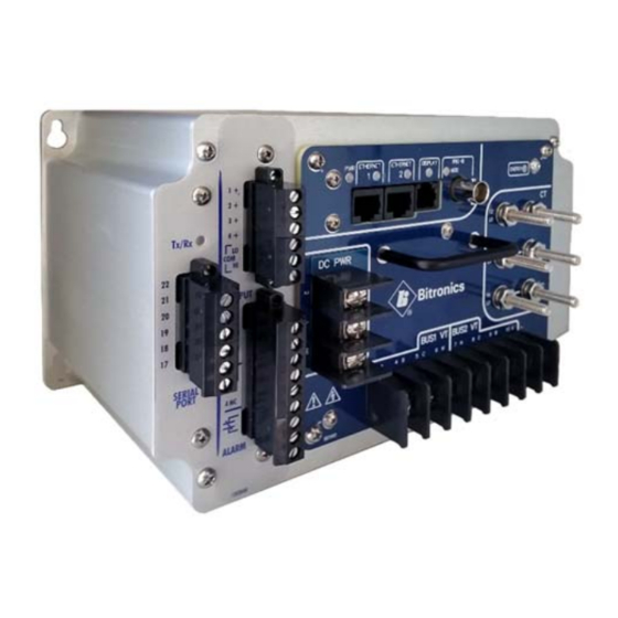
2.0 PHYSICAL CONSTRUCTION & MOUNTING The PPX II are packaged in rugged aluminum case specifically designed to meet the harsh conditions found in utility and industrial applications. The connection view is shown in Figure 3A and 3B (depending on options) for the standard chassis and Figure 3C for the extended chassis. - Page 28 Figure 3B – PPX II Connection View with Options in Standard chassis for Display port, IRIG-B port, Energy Pulse LED Figure 3C – PPX II Connection View in extended chassis with Options for Display port, IRIG-B port, Energy Pulse LED, serial port and digital I/O ML0044B December 1, 2017 Copyright 2016 Bitronics, LLC...
- Page 29 Figure 4A - Mounting and Overall Dimensions PPX II in Standard Chassis (back panel may vary as a result of options ordered) ML0044B December 1, 2017 Copyright 2016 Bitronics, LLC...
- Page 30 Figure 4B – Mounting and Overall Dimensions PPX II in Extended Chassis (back panel may vary as a result of options ordered) ML0044B December 1, 2017 Copyright 2016 Bitronics, LLC...
- Page 31 The Front panel view for the optional PowerPlex II Tethered Display (PPX II-TD) is shown in Figure 5. The mechanical dimensions are shown in Figure 6. Figure 5 – Front View of the PPX IITD ML0044B December 1, 2017 Copyright 2016 Bitronics, LLC...
- Page 32 Figure 6 - Mounting and Overall Dimensions of Optional PPX IITD ML0044B December 1, 2017 Copyright 2016 Bitronics, LLC...
-
Page 33: Installation
2.1 Installation WARNING - INSTALLATION AND MAINTENANCE SHOULD ONLY BE PERFORMED BY PROPERLY TRAINED OR QUALIFIED PERSONNEL. 2.2 Initial Inspection Bitronics instruments are carefully checked and "burned in" at the factory before shipment. Damage can occur however, so please check the instrument for shipping damage as it is unpacked. -
Page 34: Overcurrent Protection - Aux Pwr (Universal - High Range Power Supply)
2.4.3 Overcurrent Protection – AUX PWR (Universal - High Range Power Supply) To maintain the safety features of this product an external fuse shall be provided at the AUX PWR supply input and must be connected in series with the ungrounded/non- earthed (hot) side of the supply input terminals prior to installation. -
Page 35: Connections & Wiring
3.0 CONNECTIONS & WIRING The connection view of the PPX II is shown in figure 3. See Appendix A1 for detailed wiring diagrams covering the CT/VT measurement inputs. 3.1 Auxiliary Power The PPX II is powered by connections to L1(+) and L2(-). A green LED Power (PWR) indicator is provided on the front panel to indicate that the unit is powered ON. -
Page 36: Vt Inputs - Va, Vb, Vc, Vn (See Appendix A1 And Section 1.3)
3.2 VT Inputs – VA, VB, VC, VN (See Appendix A1 and Section 1.3) The PPX II is capable of monitoring two voltage buses, designated as Bus 1 (Terminals 3-6) and Bus 2 (Terminals 7-10). Voltage signals are measured using a 12.06Mohm (12Mohm/60.3Kohm) resistor divider with a continuous voltage rating of 7kV. -
Page 37: Network Settings
PPX II is offered with dual standard Ethernet 10/100 Megabit (Mb) RJ45 (copper) interfaces (10BASE-T and 100BASE-TX) which automatically selects the most appropriate operating conditions via auto-negotiation. This interface is capable of operating either as half-duplex (compatible with all Ethernet infrastructure) or full- duplex interfaces (which allow a potential doubling of network traffic). - Page 38 Determining the IP Address if unknown: Bitronics has created a utility program to request the IP address for a specific MAC address on an Ethernet network. This program can be used with the PPX II. The program is available on the company website http://www.novatechweb.com/downloads/inarp/ The program uses the Inverse Address Recognition Protocol to perform the lookup and thus is called inarp.
-
Page 39: Indicators - Ethernet (Act) Leds
The inarp utility is Copyright (c) 2011 by Bitronics, LLC. All rights reserved. Portions of inarp are Copyright (c) 1999 - 2005 NetGroup, Politecnico di Torino (Italy), and Copyright (c) 2005 - 2010 CACE Technologies, Davis (California) 3.4.2 Indicators – Ethernet (ACT) LEDs There are 2 LEDs on the front panel to indicate activity is occurring on the communication ports. - Page 40 To upload the new firmware, first obtain a copy of the firmware image. The firmware image is a binary file, less than 2 MB in length, that can be attached to email, distributed on a CD, or downloaded from an FTP site as circumstances dictate. Place a copy of the firmware image on your computer then access the upload page from the Firmware Upload link on the Configuration Settings page.
-
Page 41: Optional Serial Port (Option Includes Digital Io) - Extended Chassis Only
browse to find the configuration file you wish to load. Once selected, click on Submit, and then you will need to reboot the unit. 3.5 Optional Serial Port (option includes Digital IO) – Extended Chassis Only The PPX II has an optional serial port that is user configurable for RS232 or RS485, and support baud rates up to 115200. -
Page 42: Optional Display Port (Option Includes Irig-B And Energy Pulse Led)
Figure 8 - Typical RS-485 Cable Wiring 3.6 Optional Display Port (option includes IRIG-B and Energy Pulse LED) The PPX II has an option for adding a display port for use with the tethered display or for using as a RS232 serial port. When ordering this, an IRIG-B port is also added along with and Energy Pulse LED. - Page 43 Figure 9 – Tethered Display: PPX IITD Cable Wiring Diagram ML0044B December 1, 2017 Copyright 2017 Bitronics, LLC...
-
Page 44: Display Screens (Optional Display)
3.6.1 Display Screens (Optional Display) The PPXIITD can display several per-phase and total quantities for the circuit being monitored. In order to make all quantities available, the display scrolls from quantity to quantity approximately every 5 seconds. The quantities are refreshed once a second. The Alphanumeric display at the bottom of the instrument indicates to the user what quantity is being displayed. - Page 45 the display to 4 digits in the Watt and/or VAR display, however this is a restriction for the display only, internally the instrument still carries full precision. ML0044B December 1, 2017 Copyright 2017 Bitronics, LLC...
-
Page 46: Overview - Buttons Functions (Optional Display)
3.6.2 Overview – Buttons Functions (Optional Display) Figure 10 – Button functions for Display Mode Figure 11 – Button functions in Set-up Mode ML0044B December 1, 2017 Copyright 2017 Bitronics, LLC... -
Page 47: Keypad Functions For Display Mode (Optional Display)
3.6.3 Keypad Functions for Display Mode (Optional Display) Measurements screens may be stepped through manually by pushing the up and down arrow keys. Pushing the Toggle (Exit) key turns the scroll function off and on. When the scroll function is activated, the measurement screens will automatically step through the user-defined screens. -
Page 48: Display Error Messages
Resets are found in setup menu 3.6.4 Display Error Messages Error messages from self test are shown on the display (PPX II). The table below summarizes the errors and the messages displayed: SELF TEST RESULT SUMMARY FOR PPX II DEVICES Fault Fault Effects of Fault... -
Page 49: Optional Irig-B Port
3.7 Optional IRIG-B Port The IRIG-B option allows PPX II system time to be regulated by an IRIG-B clock source. If the clock source is synchronized by GPS, PPX II system time can be aligned with other devices with great precision. Unmodulated IRIG-B input allows system time regulation to 1us, IRIG-B 1kHz modulated input allows system time regulation to 1ms. -
Page 50: Irig-B Electrical Specifications (Option)
Valid decoded IRIG-B information is passed to the PPX II system time process. The system time process uses the highest precision valid input to regulate system time. There are no configurable parameters for IRIG-B (signal propagation delay will need to be added). - Page 51 reverses. The KY element refers to a two-wire variant of KYZ, where only the K and Y wires are used in a “normally open” configuration. The intent of both KY and KYZ elements are mainly for meter verification and the output of energy pulses are sent to an external counter.
- Page 52 The time between rising edges defines the length of the energy pulse as shown below. Shorter pulses indicate a faster rate of consumption as shown in the stepped power square wave. ML0044B December 1, 2017 Copyright 2017 Bitronics, LLC...
-
Page 53: Functional Description
4.0 FUNCTIONAL DESCRIPTION 4.1 Configuration Setup of the PPX II is most easily performed using the web interface via the Ethernet service port. Basic configuration can also be handled from the front display by entering the setup mode. 4.2 HTML Web Server The PPX II incorporates an internet-compatible HTML web page. -
Page 54: Performing Set-Up Through The Web
4.4 Performing set-up through the web page interface This section will assume you are able to use the factory default IP address of 192.168.0.171 to connect to the web page using an HTML web server. If this is not the case you may need to refer to section 3.5.1 (Network settings) to change your network configuration settings. - Page 55 Data page: Five views – Instantaneous, Demands, Vector Diagram, Synchronizing, and Trend Log ML0044B December 1, 2017 Copyright 2017 Bitronics, LLC...
- Page 56 ML0044B December 1, 2017 Copyright 2017 Bitronics, LLC...
- Page 57 ML0044B December 1, 2017 Copyright 2017 Bitronics, LLC...
- Page 58 ML0044B December 1, 2017 Copyright 2017 Bitronics, LLC...
- Page 59 The data page for trend recording gives information about the trend record, but also provides for retrieving it, or part of it via start and end times, in .csv format. One trend record contains a timestamp and values for all measurements that are selected for recording for that instant or time interval, depending on the configuration.
- Page 60 Settings page: Click on one of the settings categories (Identity, Input, Network, Display, etc.) to be taken to the next page. Contact Page: ML0044B December 1, 2017 Copyright 2017 Bitronics, LLC...
- Page 61 ML0044B December 1, 2017 Copyright 2017 Bitronics, LLC...
- Page 62 Settings Page Selections: From the Settings page screen you can select one of the following selections: Identity– This page allows the user to enter information that is necessary to identify the meter. It gives an identity to a particular PPX II. Each PPX II should have different information entered for its identity.
- Page 63 PPX II configuration changes require the unit to be rebooted. Configuration settings for the PPX II are stored in flash memory. ML0044B December 1, 2017 Copyright 2017 Bitronics, LLC...
- Page 64 Identity: ML0044B December 1, 2017 Copyright 2017 Bitronics, LLC...
- Page 65 Input: ML0044B December 1, 2017 Copyright 2017 Bitronics, LLC...
- Page 66 Network: Serial Port (if option ordered): Select the function of each serial port and set the corresponding serial parameters. The serial port functions are SCADA, Display, and Disabled. Please note that only ML0044B December 1, 2017 Copyright 2017 Bitronics, LLC...
- Page 67 one serial port may function as a display port at a time. The Display port only supports RS232. Protocol Selection: First select between Modbus or DNP3. You will then select Optimal Resolution (default) or Primary Units. Next you will choose a session. Under Type, there will be 4 different selections for Modbus and 3 for DNP3.
- Page 68 DNP3 Serial – Basic Modbus Serial ML0044B December 1, 2017 Copyright 2017 Bitronics, LLC...
- Page 69 DNP TCP - Advanced DNP Serial - Advanced ML0044B December 1, 2017 Copyright 2017 Bitronics, LLC...
- Page 70 Modbus TCP - Primary Units ML0044B December 1, 2017 Copyright 2017 Bitronics, LLC...
- Page 71 IEC61850: (If option is purchased) IED Capability Description (ICD) file: The PPX II ICD file is an IEC61850 Substation Configuration Language (SCL) file which contains the IEC61850 'capability' description of the PPX II IED. It is used by the IEC61850 IED Configurator tool to perform an IEC61850 configuration.
- Page 72 The built-in Web browser in the PPX II IED is then used to upload the configuration file from the PC and reboot the PPX II device. The CID file is stored in flash memory of the PPX II device after reboot, and will remain the active configuration until a new configuration is uploaded or the user overwrites the configuration with a built-in demo configuration.
- Page 73 Time Sync Settings: The time may be set by manually entering the time in the box for “User-defined time” or may be “Set to PC time” by clicking on that selection ML0044B December 1, 2017 Copyright 2017 Bitronics, LLC...
- Page 74 Load/Store Device Settings: ML0044B December 1, 2017 Copyright 2017 Bitronics, LLC...
- Page 75 Password Security Settings: Firmware Upload: ML0044B December 1, 2017 Copyright 2017 Bitronics, LLC...
- Page 76 Trend Recorder: The trend recorder allows up to 65 of the 200+ available measurements to be recorded at intervals of once per second or slower. The maximum is 10 measurements at intervals of once every other cycle or once per cycle (30x/sec or 60x/sec, respectively, at 60 Hz, and 25x/sec or 50x/sec at 50 Hz).
- Page 77 ML0044B December 1, 2017 Copyright 2017 Bitronics, LLC...
- Page 78 Status Page: The IED Status page shows the status of the IEC61850 communications interface (if option ordered) and the health status. The IEC61850 status states are Operational and Not Running. When the 61850 stack is not running, the reason is displayed. When the 61850 stack is not able to start due to an error, the startup log is displayed for additional detail.
- Page 79 ML0044B December 1, 2017 Copyright 2017 Bitronics, LLC...
- Page 80 ML0044B December 1, 2017 Copyright 2017 Bitronics, LLC...
-
Page 81: Navigating The Ppx Iitd's Setup Menu From The Front Panel
4.5 Navigating the PPX IITD’s setup menu from the front panel ML0044B December 1, 2017 Copyright 2017 Bitronics, LLC... - Page 82 SCRN ENA [Amps Φ] Amps A, B C Amps R] Amps Reidual [kVolts Φ] Volts AN, BN, CN [kVolts] Volts AB, BC, C [Watts Φ] WattsA, B,C [kVARΦ] VARs A, B, C [kW∙kVAR] Total Watts∙ Total VARs [kVAΦ] VAs A, B, C [PFΦ] Power Factor A, , C [kVA∙PF] Total VAs ∙ 3Φ PF [Hz] Frequeny [kWh] kWatt‐Hour Normal(+) [‐kWh] kWatt‐Hours Reverse(‐) [+kVARh] kVAR‐Hous Laggin(+) [‐kARh] kVA‐Hours Leading(‐) [kVAh] kVA‐Hours [kWhNE] kWatt‐Hours Net [kW∙PF∙Hz] Total Watts ∙ 3Φ PF ∙ Frequency [AmpsDmd] Demand Amps A,B,C [AmpsDmd axDmand Amps A,B,C ...
- Page 83 ML0044B December 1, 2017 Copyright 2017 Bitronics, LLC...
- Page 84 ML0044B December 1, 2017 Copyright 2017 Bitronics, LLC...
- Page 85 How to Enter an Integer: Increment highlighted digit by 1. ENTER Highlight Previous/Next digit. Exit to menu EXIT How to Enter a Floating Point Number: Increment highlighted digit by 1. ENTER Shifts decimal point one place to right. Decimal moves to left‐most digit when right‐most digit is passed. Highlight Next digit. Highlights left‐most digit when right‐ most digit is passed. Exit to menu EXIT How to Enter an IP address: Increment highlighted digit by 1. ENTER Highlight Previous/Next digit. Numbers scroll left and right to follow highlighted digit. Exit to Network menu EXIT ML0047 December 1, 2017 Copyright 2017 Bitronics, LLC...
-
Page 86: Measurements
5.0 MEASUREMENTS Basic measurement quantities are calculated and updated every cycle. These quantities include RMS Amperes and RMS Volts, Watts, VARs, VAs, Power Factor, all harmonic-based measurements (such as fundamental-only quantities), Energy, and Frequency, and Phase Angle. Note: For all of the following measurements, it is important to keep in mind that the specific protocol used to access the data may affect the data that is available, or the format of that data. -
Page 87: Voltage Channels
5.3 Voltage Channels The PPX II uses a unique voltage connection method, which is combined with simultaneous sampling to provide an extremely flexible voltage measurement system. All voltage inputs are measured relative to a common reference level (essentially panel ground). See Appendix 1 for input connection information. Because all signals are sampled at the same instant in time, common mode signals can be removed by subtraction of samples in the DSP, instead of the more traditional difference amplifier approach. -
Page 88: Power Factor
5.5 Power Factor The per-phase Power Factor measurement is calculated using the "Power Triangle", or the per-phase WATTS divided by the per-phase VAs. The Total PF is similar, but uses the Total WATTS and Total VAs instead. The sign convention for Power Factor is shown in Figure 12. - Page 89 For example, on a system with a lagging load on one phase and an equal leading load on another phase, the Geometric VA result will be reduced relative to a balanced system, but the Total Power Factor will still be "1". Figure 12 - Sign Conventions for Power Measurements (P is Power, Q is VARS and S is VA) ML0047...
-
Page 90: Compensated Watts And Vars (Line And Transformer Loss Compensation)
5.7 Compensated Watts and VARs (Line and Transformer Loss Compensation) The total Watt and Var losses can be calculated using five user entered parameters and measured current and voltage values. These losses are added or subtracted to/from the measured Total Watts and Total Vars when accumulating Energy. ... -
Page 91: Energy
B, C, and D. Users who do not intend to use system losses should simply set E equal to zero. A detailed application note on loss compensation in the PPX II can be found in the documentation library of the Novatech website, www.novatechweb.com. 5.8 Energy Separate values are maintained for both positive and negative Watt-hours, positive and negative VAR-hours, and VA-hours, for each feeder. -
Page 92: Frequency
reset. All values are reset simultaneously. Refer to the appropriate protocol manual for details. 5.9 Frequency Frequency is calculated every cycle for every input. The PPX II monitors the change in Phase Angle per unit time using the Phase Angle measurement for the fundamental generated by the FFT. -
Page 93: Ampere And Fundamental Ampere Demand
Demand Quantity Phase Reference Function Total VARs (A, B, C, Total) Phase, Total Present, Max, Min Total VAs (A, B, C, Total) Phase, Total Present, Max, Min 5.10.1 Ampere and Fundamental Ampere Demand Present Ampere Demands are calculated via the instantaneous measurement data used to calculate the per-phase Amperes. -
Page 94: Demand Resets
5.10.4 Demand Resets The demand values are reset in 3 groups: current, voltage, and power. This can be accomplished via the front display or from a web browser. 5.10.5 Demand Interval The PPX II uses 900 seconds (15 minutes) as the default demand interval for current. The default for average volts and average power measurements is 60 seconds. -
Page 95: Fundamental Current
peak demand. By creating a measurement that is based on a fixed value, TDD is a "better" measure of distortion problems. Traditional THD is determined on the ratio of harmonics to the fundamental. While this is acceptable for voltage measurements, where the fundamental only varies slightly, it is ineffective for current measurements since the fundamental varies over a wide range. -
Page 96: K-Factor
Fundamental Volts for that phase (which is the denominator), and the result will be the actual RMS magnitude of the selected harmonic. Fundamental Volts and Amps can be used in conjunction to obtain Fundamental VAs, and when used with Displacement Power Factor can yield Fundamental Watts and Fundamental VARs. -
Page 97: Slip Frequency (1-Cycle Update)
In addition, the Phase Angle is calculated for the Bus 1 to Bus 2 per-phase Fundamental Voltages and Fundamental Voltage to Fundamental Current. It is the Bus 1 Fundamental Voltage angle minus either the Bus 1 Fundamental Current or Bus 2 Fundamental Voltage angle for a given phase. - Page 98 SELF TEST RESULT/HEALTH CHECK ERROR CODES FOR PPX II DEVICES Fault Effects of Fault Corrective Action Input gain Calibration constants for the input gain Return to calibration are in error. The communication option factory for checksum output is reduced in accuracy to repair error approximately +/-3%.
-
Page 99: List Of Available Measurements & Settings
5.13 List of Available Measurements & Settings Available Measurements Alarm Output Heartbeat Amps A, B, C, Residual K-factor Amps A, B, C, Residual Average 3-phase Amps Meter Type Average 3-Phase Volts (1 & 2), L-L, L-N Phase Angle Amps A, B, C Average Volts AN, BN, CN, AB, BC, CA (Bus 1 Phase Angle Volts A, B, C &... -
Page 100: Calibration
5.14 Calibration Routine re-calibration is not recommended or required. A field calibration check every few years is a good assurance of proper operation. 5.15 Instantaneous Measurement Principles The PPX II measures all signals at an effective rate of 64 samples/cycle, accommodating fundamental signal frequencies from 20 to 75Hz. -
Page 101: Appendix
APPENDIX A1 CT/VT Connection Diagrams Please note that there is an option on the Settings/Input page to invert the CT Polarity (see screen shot clip below). This option is the equivalent of swapping the connections in the connection diagrams below at the HI and LO terminals for each CT input, that is, swapping 11 and 12 (IA), 13 and 14 (IB), and 15 and 16 (IC). - Page 102 Figure 13 - Signal Connections – PPX II ML0047 December 1, 2017 Copyright 2017 Bitronics, LLC...
-
Page 103: A2 Ethernet Troubleshooting
A2 Ethernet Troubleshooting If the Link LED fails to illuminate, this is an indication that there is trouble with the connection and communication will not proceed without solving the problem. If a copper connection is used between the PPX II and the hub/switch, check the following items: Verify that the connectors are fully engaged on each end. -
Page 104: A3 Setting Screen Configurations On Powerplex Ii For Ppxiitd - Screen Enable & Custom Display Screens
A3 Setting Screen configurations on PowerPlex II for PPXIITD – Screen Enable & Custom Display Screens Screen Enable: ML0047 December 1, 2017 Copyright 2017 Bitronics, LLC... - Page 105 Custom Display Screen Settings: Two Sections – Build/Edit and Summary The Custom Display Screen Configuration page contains two sections: the Build/Edit panel and the Summary panel. One custom display screen is built at a time in the Build/Edit panel and is then added to the Summary panel, which presents a list of all the custom screens that have been built.
- Page 106 The order of the screens can be changed by selecting a screen from the list and clicking on the up or down arrows. ML0047 December 1, 2017 Copyright 2017 Bitronics, LLC...
-
Page 107: A4 Powerplex Ii Display Screens - Standard Formats
A4 PowerPlex II Display Screens – Standard Formats INSTANTANEOUS DISPLAY SCREENS Format Quantity 00000 Phase A Amperes 00000 Phase B Amperes 00000 Phase C Amperes AmpsΦ 00000 Residual Amperes Unused Unused AmpsR 00000 Phase A Volts 00000 Phase B Volts 00000 Phase C Volts xVolts... - Page 108 00000 Phase A VAs 00000 Phase B VAs 00000 Phase C VAs xVA Φ 00000 Phase A PF 00000 Phase B PF 00000 Phase C PF PF Φ 10. 00000 Total VAs 00000 3Φ PF Unused xVAsPF 11. 00.000 Frequency ...
- Page 109 16. 000.00 VA hours (Most significant half) 000.00 VA hours ( Least significant half) Unused kVAh 17. 00000 Watt hours Net (Most significant half) 00000 Watt hours Net (Least significant half) Unused kWh NET 18. 00000 Total Watts 00000 3Φ...
- Page 110 DEMAND DISPLAY SCREENS Format Quantity 19. 000.00 Phase A Amps Demand 000.00 Phase B Amps Demand 000.00 Phase C Amps Demand Amps Dmd 20. 00000 Phase A Maximum Amperes Demand 00000 Phase B Maximum Amperes Demand 00000 Phase C Maximum Amperes Demand Amps MAX 21.
- Page 111 00000 Phase C-A Minimum Volts Demand xV MIN 28. 00000 Total Maximum Watt Demand 00000 Total Watts (Also on Screen 7) 00000 Total Minimum Watt Demand xW 29. 00000 Total Maximum VAR Demand 00000 Total VARs (Also on Screen 7) 00000 Total Minimum VAR Demand xVAR ...
- Page 112 HARMONIC SUMMARY DISPLAY SCREENS Format Quantity 31. 00000 Phase A Fundamental Amperes 00000 Phase B Fundamental Amperes 00000 Phase C Fundamental Amperes Fnd Amps 32. 00000 Fundamental Residual Amperes Unused Unused FndN Amps 33. 00000 Phase A Fundamental Volts 00000 Phase B Fundamental Volts 00000...
- Page 113 00.000 K-Factor Phase C (Current) K-Factor - WYE meters only x - indicates blank, (k)ilo, (M)ega, or (G)iga ML0047 December 1, 2017 Copyright 2017 Bitronics, LLC...
- Page 114 HARMONIC SUMMARY DISPLAY SCREENS (Cont’d) Format Quantity 39. 0.0000 Phase A Displacement PF 0.0000 Phase B Displacement PF 0.0000 Phase C Displacement PF DispPF Φ 40. 00000 3Φ Displacement PF Unused Unused DispPF T 41. 000.00 Phase A Fundamental Demand Amps 000.00 Phase B Fundamental Demand Amps 000.00...
- Page 115 46. 000.00 Phase A Minimum Average Watts 000.00 Phase B Minimum Average Watts 000.00 Phase C Minimum Average Watts xW Min 47. 000.00 Phase A Average VARs 000.00 Phase B Average VARs 000.00 Phase C Average VARs xVAR Avg 48. 000.00 Phase A Maximum Average VARs 000.00 Phase B Maximum Average VARs...
- Page 116 54. 00000 Phase A-B Secondary Volts 00000 Phase B-C Secondary Volts 00000 Phase C-A Secondary Volts SecVolts 55. 000.00 Auxiliary Voltage Unused Unused V aux - Screen available on WYE meters only x - indicates blank, (k)ilo, (M)ega, or (G)iga - 116 - ML0044B December 1, 2017...
- Page 117 A5 PowerPlex II Standard Display Screens – Visual Representations PPXIITD - 117 - ML0044B December 1, 2017 Copyright 2017 Bitronics, LLC...
- Page 118 - 118 - ML0044B December 1, 2017 Copyright 2017 Bitronics, LLC...
- Page 119 - 119 - ML0044B December 1, 2017 Copyright 2017 Bitronics, LLC...
- Page 120 - 120 - ML0044B December 1, 2017 Copyright 2017 Bitronics, LLC...
- Page 121 - 121 - ML0044B December 1, 2017 Copyright 2017 Bitronics, LLC...
- Page 122 - 122 - ML0044B December 1, 2017 Copyright 2017 Bitronics, LLC...
- Page 123 - 123 - ML0044B December 1, 2017 Copyright 2017 Bitronics, LLC...
- Page 124 - 124 - ML0044B December 1, 2017 Copyright 2017 Bitronics, LLC...
- Page 125 - 125 - ML0044B December 1, 2017 Copyright 2017 Bitronics, LLC...
- Page 126 - 126 - ML0044B December 1, 2017 Copyright 2017 Bitronics, LLC...
- Page 127 - 127 - ML0044B December 1, 2017 Copyright 2017 Bitronics, LLC...
- Page 128 - 128 - ML0044B December 1, 2017 Copyright 2017 Bitronics, LLC...
- Page 129 - 129 - ML0044B December 1, 2017 Copyright 2017 Bitronics, LLC...
- Page 130 - 130 - ML0044B December 1, 2017 Copyright 2017 Bitronics, LLC...
- Page 131 - 131 - ML0044B December 1, 2017 Copyright 2017 Bitronics, LLC...
- Page 132 - 132 - ML0044B December 1, 2017 Copyright 2017 Bitronics, LLC...
- Page 133 Revision Date Changes 10/29/2014 Original Issue E. DeMicco 10/19/15 – Added PPX IITD display and new PPX II E. DeMicco 7/18/16 options (display port, IRIG-B port) R. Fisher Added Hi-Range Power supply specifications, overcurrent protection and Supply/Mains Disconnect. Added specifications for PPX II-TD display and IRIG-B.
- Page 134 Added screw torque spec (ground bond) in section 1.3 table under Physical/Size description. Section 1.5 revision for the following: New Directives 2014/30/EU (EMCD) and 2014/35/EU (LVD), AC Power Line Conducted Emissions, AC Dips & Interruptions, EFT, and Surge; Revised applicable dates pertaining to Surge and Conducted Disturbances standards.
- Page 135 - 135 - ML0044B December 1, 2017 Copyright 2017 Bitronics, LLC...
- Page 136 Bitronics, LLC 261 Brodhead Road,Bethlehem, PA. 18017 (610) 997-5100 Fax (610) 997-5450 www.novatechweb.com /bitronics...
Need help?
Do you have a question about the Bitronics PowerPlex II and is the answer not in the manual?
Questions and answers