Table of Contents
Advertisement
Quick Links
Advertisement
Table of Contents

Related Manuals for Trotec Airgoclean One


Summary of Contents for Trotec Airgoclean One
- Page 1 ® AIRGOCLEAN OPERATING MANUAL AIR CLEANER...
-
Page 2: Table Of Contents
Safety .................. 2 Information about the device.......... 4 ® AirgoClean Transport and storage............ 6 Assembly and start-up............ 6 https://hub.trotec.com/?id=44900 Operation ................ 7 Safety Available accessories............ 14 Read this manual carefully before starting or using the Errors and faults.............. 14 device. Always store the manual in the immediate vicinity Maintenance ................ 16... - Page 3 • Never select automatic mode if the device is used for virus filtration. • The indicated measured values are considered indicators and not guaranteed measured values. • Only use filters and accessory recommended by Trotec for the AirgoClean One. air cleaner AirgoClean^®^ One...
-
Page 4: Information About The Device
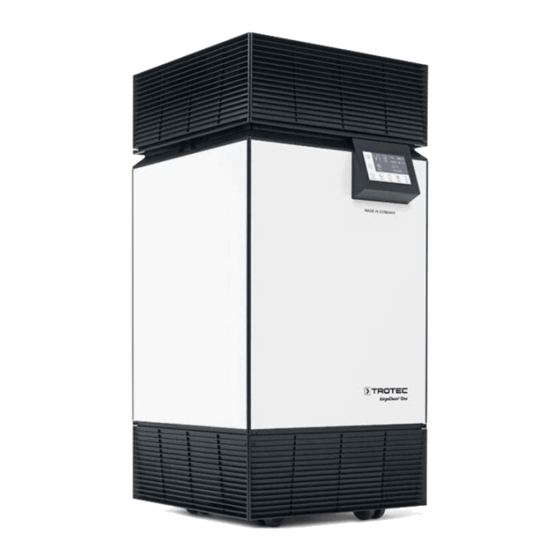
Residual risks Information about the device Warning of electrical voltage Device description Work on the electrical components must only be The device serves to filter the room air with the aim of reducing carried out by an authorised specialist company! slight and medium contaminations and odours in order to Warning of electrical voltage improve the air quality. - Page 5 Device depiction Designation Top section with air outlet Handle strip Control panel Air inlet with cover Mains plug with mains switch Wheels Box with air quality sensors Remote control Standard configuration Designation F7 prefilter with filter fleece HEPA filter H14 complying with EN 1822 Silencer If an activated carbon filter (optional) is inserted, please not the configuration that applies:...
-
Page 6: Transport And Storage
Start-up Transport and storage Prefilter, HEPA filter and silencer are already built into the Note device. If you store or transport the device improperly, the Note device may be damaged. Remove any packaging material from the prefilter, Note the information regarding transport and storage of HEPA filter and silencer. -
Page 7: Operation
Connecting the power cable Switching the device on • Plug the power cable into the device. Once you have completely installed the device as described in the Start-up chapter, you can switch it on. • Insert the mains plug into a properly fused mains socket. Please proceed as follows to switch the device on: Operation 1. - Page 8 symbol (Back) to confirm your entry. English ð The basic settings have now been made. Lock Info Reset Info If you select Info in the submenu, the contact details of Trotec will be displayed. Warnings History Filter Operation Back 3. Select the symbol (Increase value) or symbol (Decrease value) to select from the...
- Page 9 3. Select Filter 1, Filter 2 or Filter 3 by tapping Filter menu symbol (Increase value) or the symbol (Decrease Before you start the device for the first time or after a filter value). change, you must reset the individual filters. When changing the ð The selected filter is highlighted in white colour. standard configuration, it is also required to adjust the filter ð...
- Page 10 Setting the operating mode Air quality: fine dust value The device has the following operating modes: The Particles indication shows the concentration of fine • Automatic mode particulates in the air. • Night mode Particulate matter is considered to be a serious contributor to respiratory problems, the increase in asthma attacks as well as •...
- Page 11 The higher the pollution by gaseous pollutants, the more dots 3. Press the symbol (24-hour rhythm) or are highlighted in white which appear next to the VOC display. symbol (14-day rhythm) to display the values by means of a scale (G = Good, M = Medium, P = Poor). Load display Gaseous pollutants VOC (white dots)
- Page 12 4. Select End to set the time to stop. Manual operation 5. Select the symbol (On) to switch on the timer. You can manually select all 5 fan speeds and the turbo mode. Please proceed as follows to adjust the fan speed: ü The device is switched on. Start 1.
- Page 13 5. Select the symbol (On) to switch on the schedule. Please proceed as follows to lock the control panel: 6. Select the symbol (Back) to confirm your entry. 1. Press the symbol (On/off) for several seconds until the ð The symbol (Schedule) icon is indicated in the main control panel is locked.
-
Page 14: Available Accessories
• Check whether the mains switch (5) is set to position I. Shutdown • If the device is not starting, have the electrics checked by a specialist company or by Trotec. Warning of electrical voltage The device is loud or vibrates: Do not touch the mains plug with wet or damp hands. - Page 15 The device displays the warning "Check prefilter": • Clean the filter fleece as described in the Maintenance chapter. • If the warning does not disappear, set the AirgoClean One to fan stage zero and wait for 3 minutes. During this time, the filter monitoring sensors are calibrated.
-
Page 16: Maintenance
Maintenance intervals Maintenance Maintenance and care interval before every as needed at least every at least every at least at least every start-up 2 weeks 4 weeks annually 2 years Check air inlets and outlets for dirt and foreign objects and clean if necessary Clean the exterior Visually check the inside of the device for dirt... - Page 17 Tasks which require the device to be opened must filter depends on the ambient conditions and the only be carried out by authorised specialist application period of the device. companies or by Trotec. Note Cleaning the housing The HEPA filter, the silencer and, if necessary, the Clean the housing with a soft, damp and lint-free cloth.
- Page 18 Proceed as follows to replace the HEPA filter: 4. Dispose of the HEPA filter according to the national 1. Press the buttons of the handle strip (2). regulations. ð The top section comes off. 5. Take the new HEPA filter out of the plastic cover. 2.
- Page 19 3. The filter fleece is attached to the prefilter (9) with a Velcro Replacing the prefilter fastener. Pull the filter fleece off from the prefilter and Note clean the prefilter and filter fleece (9) with a lint-free cloth The lifetime of the prefilter is a maximum of 1 year. or carefully tap out the fleece.
-
Page 20: Disposal
You can also find out about other return options carbon filter that apply for many EU countries on the Fan stage 1 45 m 35 m 6 W website https://hub.trotec.com/?id=45090. Otherwise, please Fan stage 2 150 m 115 m 12 W contact an official recycling centre for electronic and electrical Fan stage 3 285 m... - Page 21 Spare parts drawing and list Info The position numbers of the spare parts differ from Bottom those describing the positions of other parts mentioned in this operating manual. Spare part Spare part Board (particle sensor) Cover for sensor housing Board (sensor) Lock for prefilter Wheel Positioning piece for prefilter Screw...
- Page 22 Cover lock Info The position numbers of the spare parts differ from those describing the positions of other parts mentioned in this operating manual. Spare part Spare part Washer Torsion spring Axle Hold-down device air cleaner AirgoClean^®^ One...
- Page 23 Cover Info The position numbers of the spare parts differ from those describing the positions of other parts mentioned in this operating manual. Spare part Spare part Ventilation panel Screw Cover lock Cover insulation Cover air cleaner AirgoClean^®^ One...
- Page 24 Filter housing Info The position numbers of the spare parts differ from those describing the positions of other parts mentioned in this operating manual. Spare part Spare part Screw Rubber buffer Screw Metal clamp for filter Filter case air cleaner AirgoClean^®^ One...
- Page 25 Housing Info The position numbers of the spare parts differ from those describing the positions of other parts mentioned in this operating manual. Spare part Spare part Screw Display frame Board (control) Design panel A Display Design panel B Design frame Design panel C Corner profile air cleaner AirgoClean^®^ One...
- Page 26 Info The position numbers of the spare parts differ from those describing the positions of other parts mentioned in this operating manual. Spare part Spare part Screw Sealing cord Board (distributor) Mains connection Screw Fan casing Screw Fan housing cover Inlet nozzle Fan housing (expanded polypropylene) Valve insulation air cleaner AirgoClean^®^ One...
- Page 27 Trotec GmbH Grebbener Str. 7 D-52525 Heinsberg +49 2452 962-400 +49 2452 962-200 info@trotec.com www.trotec.com...
Need help?
Do you have a question about the Airgoclean One and is the answer not in the manual?
Questions and answers