Table of Contents
Advertisement
Quick Links
Advertisement
Table of Contents

Related Manuals for WOODLAND SCENICS SCENIC RIDGE ST1482


Summary of Contents for WOODLAND SCENICS SCENIC RIDGE ST1482
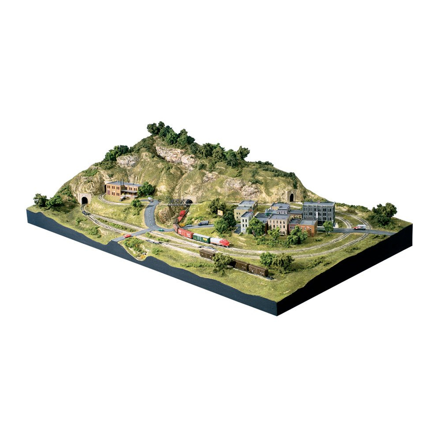
- Page 1 N SCALE COMPLETE LIGHTWEIGHT LAYOUT KIT ST1482 INSTRUCTION BOOKLET...
-
Page 2: Table Of Contents
CONTENTS Introduction Layout Overview 5 and 6 Scenic Ridge Kit Contents Adhesives and Speci al Tools Low Temp Foam Glue Gun ..............8 Foam Tack Glue .................. 8 Hot Wire Foam Cutter ................ 9 Track Begin Layout Assembly Glue Base Panels ................9 Assemble Track ................... - Page 3 Test and Trace Track on Risers ............24 Lay Track-Bed ................... 25 Glue the Track ................... 25 Rock Castings, Tunnel Portals and Culverts Make Rock Castings ................. 26 Install Rock Castings ............... 26 Color Rocks ..................27 Color and Install Tunnel Portals ............. 27 Color, Assemble and Install Culverts ..........
-
Page 4: Introduction
These tools make building the Scenic Ridge Layout Kit easier and more efficient. Purchase at your favorite hobby shop. When building Scenic Ridge, know that mistakes can be fixed. Woodland Scenics Systems are designed to leave room for error and modelers can go back and fix problem areas. - Page 5 Layout Overview 1. Risers and Inclines/Declines Install Risers and Inclines/Declines over Track Plan printed on Foam Base Panels. 2. Tunnel Work for Risers Add Plaster Cloth, Track-Bed, track and Ballast to Risers along tunnel area. Install foam Tunnel Portals and tunnel walls. 3.
-
Page 6: Layout Overview 5 And
Layout Overview 6. Lay Track-Bed Lay Track-Bed over Risers covered in Plaster Cloth. Add track and rock faces. 7. Apply Earth Undercoat Install Tunnel Portals and paint the Plaster Cloth with Earth Undercoat. 8. Add Road System Use the Road System to create realistic roads and building foundations. -
Page 7: Scenic Ridge Kit Contents
Kit Contents 3 Pre-printed Foam Base Panels Hob-e-Tac ® 1/2" x 24" x 36" (1.27 cm x 60.9 cm x 91.4 cm) 1 fl oz (29.5 mL) 10 Profile Boards™ Foam Tack™ Glue 8" x 24" (20.3 cm x 60.9 cm) 8 fl oz (236 mL) 6 Profile Board Connectors Earth Undercoat... -
Page 8: Adhesives And Special Tools
Adhesives and Special Tools Woodland Scenics offers two types of adhesive for use with SubTerrain Lightweight Layout System. Each has advantages for different jobs. General instructions for using both appear below. Scenic Ridge instructions were written using Low Temp Foam Glue Gun and Low Temp Foam Glue Sticks to complete the kit. -
Page 9: Hot Wire Foam Cutter
Hot Wire Foam Cutter (ST1435) The Hot Wire Foam Cutter is designed for use with Woodland Scenics foam products. When using with other foam products, toxic fumes may be emitted. The Foam Cutter Bow & Guide (ST1437) makes the Hot Wire Foam Cutter even more versatile. -
Page 10: Install Risers
Install Risers Risers elevate track to allow for the addition of ditches, creeks and low-lying areas without cutting into the base. The 2" Risers included in this kit 2" Riser are enough to complete the provided track plan. Additional Risers have been provided for NTRAK modular option (see information on pages 42-43). -
Page 11: Install Second Tier Risers
Fig. 7 Fig. 6 1. Place a 0-1” Incline/Decline section on top of Riser where noted, “Start incline for second tier inside track here” (Fig. 8). Using Foam Nails, pin the 0-1”section in place on Riser in a counter-clockwise direction (Fig. 6). We recommend using Foam Tack Glue to attach the thin end of the starter piece. -
Page 12: Overpass And Bridge Cut And Install Overpass
the highest end of the Incline/ Fig. 9 Decline. Trim with a Hot Wire Foam Cutter or hobby knife (Fig. 9). 4. When the entire second tier is in place, glue to the bottom Risers. 5. Remove Foam Nails when glue has set. -
Page 13: Tunnel Work
Fig. 11 INCLINE/DECLINE INCLINE/DECLINE STARTER STARTER 3. From a 1/4" Foam Sheet, cut a 2 1/2" x 7" piece. Glue the piece in place, overlapping the ends of the Risers equally on either side of the gap. 4. Glue the cut Incline/Decline Starter pieces on top of the Riser, butting the 1/4"... -
Page 14: Lay Track-Bed
2. To apply Plaster Cloth, hold the Fig. 13 piece by the corners, dip it in water and place on Risers with the bumpy side up. Sheets should overlap sides of Riser about 1/2" to 1" (Fig. 13). 3. Starting approximately 6" outside the Tunnel Portals (marked on the pre-printed track plan) and working 6"... -
Page 15: Install Track And Ballast In Tunnel Areas
Fig. 16 Fig. 15 Glue Traced Glue Line 3" Install Track and Ballast in Tunnel Areas 1. Replace track over entire layout. Pin down the sections inside Tunnel. 2. When you are satisfied with placement, remove the track that is outside the Tunnel area, leaving the track inside the Tunnel area in place. -
Page 16: Foam Tunnel Portals
Fig. 21 Fig. 20 Tunnel Portal Patterns Foam Tunnel Portals 1. Trace four Tunnel Portal Patterns onto a 1/2" Foam Sheet (Fig. 20). Cut out with hobby knife or Foam Knife. Foam tunnel portals provide a stable backing for Hydrocal Tunnel Portals. 2. -
Page 17: Install Profile Boards
sides of the Risers (Fig. 22). The tops of the tunnel walls should be even with the tops of the foam tunnel portals (Fig. 22 inset). Trim walls to fit. 3. Take another 6" x 24" segment and cut out two 3" x 6" segments. These are walls C and D. -
Page 18: Left-Side Profile Boards
2. Test fit the last Profile Board on the right side of layout. It will extend beyond the back corner. With a straightedge, trim to fit base exactly by cutting off approximately 1" from end (Fig. 23 inset). 3. When Profile Boards are aligned with the back edge of the base, pin in place with Foam Nails. -
Page 19: Right-Side Profile Boards
Right-side Profile Boards 1. Trim 2" off one end of the remaining 13" segment. Cut the 2" segment in half widthwise to form the last two Connectors. 2. Cut the 11" segment in half lengthwise. 3. Connect the 11" segment and the last full-length half together Fig. -
Page 20: Fill Corner Joints
Fill Corner Joints 1. Fill joints where Profile Boards interlock at corners with scraps of Profile Boards cut into 4" to 12" strips. Cut the rectangular flat areas between the ribs (Fig. 31). Strips fit the right-angle gaps of the corners. 2. -
Page 21: Flat Area B
Fig. 34 flat area B flat area A left side loop seam right-hand riser supports 2. Cut 12 supports 2 3/4” tall using scrap pieces of Profile Board or Foam Sheet. These elevate the flat areas (Fig. 34). NOTE: Extra supports may be needed if there is a seam between pieces of Foam Sheet (Fig. -
Page 22: Add Road Foundation
Add Road Foundation The Road System included with Scenic Ridge creates realistic roads and paved areas. 1. Use scrap pieces of Risers or other foam to create foundations for the roads (Fig. 35). 2. Pin the scrap pieces even with the top edge of Risers and Flat Areas. When satisfied with position of scrap pieces, glue in place. -
Page 23: Make And Place Newspaper Wads
Fig. 37 Make and Place Newspaper Wads 1. To wad a sheet of newspaper, begin at the outside of the sheet and roll the edges under to form a pillow shape. This shape is the easiest to stack for creating hills and mountains (Fig. 36). 2. -
Page 24: Test And Trace Track On Risers
Fig. 40 Fig. 39 3. Start at the bottom left-hand corner of the layout and place the strip bumpy side up over the paper wads. Leave a 1" strip overlapping edges of the layout (Fig 39). 4. Fold the overlapped end even with edge of layout to form a clean, finished edge (Fig. -
Page 25: Lay Track-Bed
Lay Track-Bed Fig. 41 1. Following the traced track plan on the Risers, glue Track- Bed over remaining surface by spreading a layer of Foam Tack Glue on bottom of the Track-Bed and another layer on the Risers (Fig. 41). Make sure Track-Bed is centered with the track tracing. -
Page 26: Rock Castings, Tunnel Portals And Culverts Make Rock Castings
Rock Castings, Tunnel Portals and Culverts Make Rock Castings 1. Make a solution of “wet water.” Mix 2 drops of liquid dish soap in 1 cup of water. Coat inside of Rock Molds with solution and pour out excess. Wet water helps disperse air bubbles in rock castings and acts as a mold release agent. -
Page 27: Color Rocks
in place until set. Use the Stir Stick to dab small amounts of Hydrocal around edge of rock where there are gaps. Keep plaster off rock face or casting will lose its rock-like detail. 6. Repeat for each rock. Let dry for a minimum of 2-3 hours before coloring. Color Rocks Color rocks using the Leopard Spot painting technique. -
Page 28: Color, Assemble And Install Culverts
Fig. 48 streambed Tunnel Portal placement Culvert placement 5. Repeat for remaining Portals (Fig. 48). Color, Assemble and Install Culverts 1. Sand Culvert pieces and paint with Black wash. Let dry. 2. Glue Culverts together at seams with Foam Tack Glue (Fig. 49). 3. -
Page 29: Add Road System
Add Road System Woodland Scenics Road System consists of Smooth-It, Paving Tape and two colors of Top Coat, Asphalt and Concrete. It makes it easy to add realistic roads, streets, sidewalks and pavement to a layout. -
Page 30: Pave Roads
3. Allow Smooth-It to dry thoroughly (about 20-30 minutes). 4. Remove Paving Tape. 5. Fill in remaining areas and smooth even with tops of existing pavement with Spreader (Fig. 53). Fig. 53 6. Let dry thoroughly and sand surface smooth. Pave Roads Fig. - Page 31 3. Stack progressively longer strips of Fig. 57 Paving Tape Paving Tape on top of the first to bring the road crossing up to the top of the rail. The last and longest piece of tape should butt against the side of the rail (Fig. 57). 4.
-
Page 32: Add Curbs, Sidewalks And Foundations
Fig. 61 building front curb, sidewalk- building Smooth-It base foundation (town area) Paving Tape street Add Curbs, Sidewalks and Foundations 1. Following the desired path of your sidewalk, curb or foundation, lay strips of Paving Tape over the existing dried Smooth-It on the inside edges of all your roads in the town area (Fig. -
Page 33: Ballast Track
Ballast Track Fig. 63 Ballast is broken stone laid along the railroad bed to stabalize ties and rails. IMPORTANT: Before Ballasting track, cover top of turnouts and switch machines with masking tape. 1. Use a paintbrush to apply Scenic Cement to sides of Track-Bed. -
Page 34: Landscape
Landscape Landscape adds depth, color, texture and realism to your layout. From ground cover and foliage to bushes and trees, the complete Landscape System offers versatile materials that blend and mix together, for ultimate realism. These easy- to-use, fail-safe materials are perfect for beginner to advanced modelers. Apply landscape materials using the box photos and the Legend on page 38 as a guide or place where you wish. -
Page 35: Medium Ground Cover
Medium Ground Cover Medium ground cover is low grasses, leaves and weeds. It is the natural rise and fall of plants that are different sizes, shapes and colors and grow in random patterns. This section also includes Talus or rock debris. Landscape materials start to overlap. -
Page 36: Clump-Foliage
Fig. 70 Fig. 69 5. Dip Armatures into Clump-Foliage bag (Fig. 69), then pinch foliage firmly on branches. Spray foliage with Scenic Cement to secure in place. 6. To plant trees, use a hobby knife to poke a small hole in layout where tree is desired. -
Page 37: Field Grass
Fig. 74 Fig. 73 Fig. 76 Fig. 75 Field Grass Use Field Grass to model weeds and tall grasses. 1. Pour a small amount of Foam Tack Glue onto a piece of scrap paper. 2. Roll a small clump of Field Grass between fingers to produce an uneven look (Fig. -
Page 38: Finishing Touches
LEGEND Trees Streambed Clump-Foliage Talus Field Grass Finishing Touches The final step is detailing. Most techniques use the same materials with slight variations in modeling principles as other steps. Let each step dry completely before moving on to the next. Drybrush Turf Add color variety to Turf, cover up bare spots or change the look of landscape. -
Page 39: Adding Additional Landscape Material
Fig. 78 Adding Additional Landscape Material To add more variety in texture, color and realism, or to cover gaps in terrain, apply additional landscape material where desired. IDEAS! Burnt Grass and Yellow Grass Fine Turf provide color variations for bushes, ground cover and trees. -
Page 40: A Final Word
You can patch up your Road System or add extra foliage to cover gaps and seams around the Tunnel Portals or Culverts. You can even purchase more Woodland Scenics Trees, buildings, Trackside Scenes or scene-setting items to personalize your Scenic Ridge Kit. -
Page 41: Products
Products If you would like to build a new layout or add landscaping to your Scenic Ridge layout, just refer to the item name and number then go to your favorite hobby store and buy what you need. ITEM NUMBER DESCRIPTION SubTerrain Items ST1408... - Page 42 PROFILE BOARD WITH 1" EDGE DOWN FRONT EDGE OF PORTAL OVERPASS SECOND TIER BRIDGE SUPPORT SPACING FRONT EDGE OF PORTAL PROFILE BOARD WITH 1/2" EDGE DOWN PROF 4" 5-1/2" 7" PROFILE BOARD CONNECTOR SUGGESTED PLACEMENT NTRAK MEASUREMENTS FROM DOTTED LINE TO FRONT OF LAYOUT...
-
Page 43: Track Plan And Layout 42 And
PROFILE BOARD WITH 1/2" EDGE DOWN FILE BOARD WITH 1" EDGE DOWN WOODLAND SCENICS SCENIC RIDGE LAYOUT ATLAS N SCALE SNAP-TRACK A = 5" STRAIGHT ......33 G = 19" RADIUS ........ 5 B = 2 1/2" STRAIGHT ....... 8 H = 1/2 - 9 3/4"... - Page 44 Follow recommendations for use and cleanup. Clean utensils in sink or pour leftover plaster mixture up spills immediately with warm soapy water. down drain. Discard leftover plaster in trash. WOODLAND SCENICS ® WOODLAND Manufactured by ®...
Need help?
Do you have a question about the SCENIC RIDGE ST1482 and is the answer not in the manual?
Questions and answers