Table of Contents
Advertisement
Quick Links
Advertisement
Table of Contents

Subscribe to Our Youtube Channel
Related Manuals for igus robolink DCi


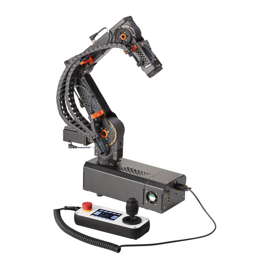
Summary of Contents for igus robolink DCi
-
Page 4: Safety Instructions
1. Safety instructions • • • • • • • • • •... - Page 5 2. Introduction 2.1 Robot components...
-
Page 6: Specification
2.2 Specification... -
Page 7: Lateral View
3. Dimensions 3.1 Lateral view Diagram 1: Side view of the DCi robot. The robot axes (motors) are basically counted from the robot base. So axis 1 is the vertical axis in the robot base. An effector (e.g., gripper) can be attached to axis 4/5 (4 or 5-axis version). -
Page 8: Hole Pattern Flange (Axis 5) And Bottom
3.2 Hole pattern flange (axis 5) and bottom Diagram 2: Top: Hole pattern flange of the axis 5; Bottom: Hole pattern of the robot base. -
Page 9: Connections And Leds
4. Connections and LEDs 4.1 Connections Diagram 3: Rear view of the robot base, here in the 5-axis version. In the 4-axis version the values in parentheses apply to the motor modules. -
Page 10: Digital Inputs/Outputs
4.2 Digital Inputs/Outputs... - Page 11 Diagram 4: Additional internal digital I/Os.
- Page 12 The use of the inputs and outputs takes place in CPRog with the number 21 upwards: I/O Module Physical input/output Name in CPRog and in the robot programme DIO 1 (standard) Din21 to Din24 on rear wall Inputs: DIn21 to DIn27 Din25 to Din27 on inner side Outputs: DOut21 to DOut27 DOut21 to DOut24 on rear wall...
- Page 13 4.3 LEDs Diagram 5: Organisation of the robot control and LED signal lights of the individual modules.
- Page 14 5. Commissioning...
-
Page 15: Operation
6. Operation 6.1 Reset errors/Enable robot... -
Page 16: Manual Method Of The Robot
6.2 Manual method of the robot... -
Page 17: Referencing The Robot
6.3 Referencing the robot... - Page 18 6.4 Starting and stopping a programme 6.5 Set the digital inputs/outputs...
-
Page 19: Display Of Status Information
6.6 Display of status information... - Page 20 7. Programming 7.1 Establish connection • • • •...
-
Page 21: Creating A Programme
7.2 Creating a programme 7.3 Uploading a programme Diagram 6: CPRog Windows software with red marked upload button. -
Page 22: Integration In Safety Circuit
8. Integration in safety circuit... - Page 23 9. Interfaces 9.1 Digital inputs and outputs 9.2 PLC interface 9.3 Plug-in interface...
-
Page 24: Cri Interface
9.4 CRI interface... -
Page 25: Extensions / Adjustments
10. Extensions / Adjustments 10.1 Galvanic isolation of digital outputs Diagram 7: Galvanic isolation of the digital outputs... - Page 26 11. Troubleshooting and support 11.1 Error codes • •...
- Page 27 11.2 CAN-Bus and CPRog status information...
- Page 28 11.3 Hardware • • • • •...
- Page 29 11.4 Software • • • • • • •...
- Page 30 11.5 Support contact ➢ ➢ ➢...
Need help?
Do you have a question about the robolink DCi and is the answer not in the manual?
Questions and answers