Table of Contents
Advertisement
Quick Links
Advertisement
Table of Contents

Related Manuals for igus Drylin Delta


Summary of Contents for igus Drylin Delta
- Page 3 Version V1.2-EN, September 2020 © Commonplace Robotics GmbH, 2011 – 2020 igus ® , drylin ® and robolink ® are registered trademarks of igus GmbH. igus ® GmbH Spicher Str. 1a 51147 Cologne Germany Phone Support: +49 (0) 2203-96498-255 ww-robot-control@igus.net...
-
Page 4: Table Of Contents
5.2. CE Certification ............................24 5.3. Integration of SIL-Rated Safety Components ................24 6. Software Installation ........................26 6.1. Installation of the iRC - igus ® Robot Control ................26 6.2. Licensing ................................. 28 6.3. Setting up the Ethernet Connection to the Embedded Computer ......... 28 6.4. - Page 5 7.8. Updating the Software ........................... 38 8. Programming the Robot with iRC ..................... 39 8.1. The Program Editor ..........................39 8.2. Comments and Information in Programs ..................42 8.3. Variables and Variable Access ......................44 8.4. Execution Flow ............................48 8.5.
-
Page 6: Safety Instructions
Robot Controller. The fan must, ideally, point upwards or to the side (reduced efficiency). The fan must not point down. Backup important data prior to installing the igus ® Robot Control software. -
Page 7: Quick Start Guide
Quick Start Guide 2.1. Set up and Connections Follow Safety Instructions, Section 1. Make sure that the on/off switch on the Control Cabinet is set to "off". Mount the Robot on a suitable base. Make sure that there is no tension on the cables. ... -
Page 8: Connect And Move The Robot
PC, see Section 6.1. Start the iRC software. On Start-up you can choose the project suitable for your Robot. Please refer to the igus product number, the project names are based on these. You can now activate the Robot by pressing: o “Connect”,... -
Page 9: Introduction
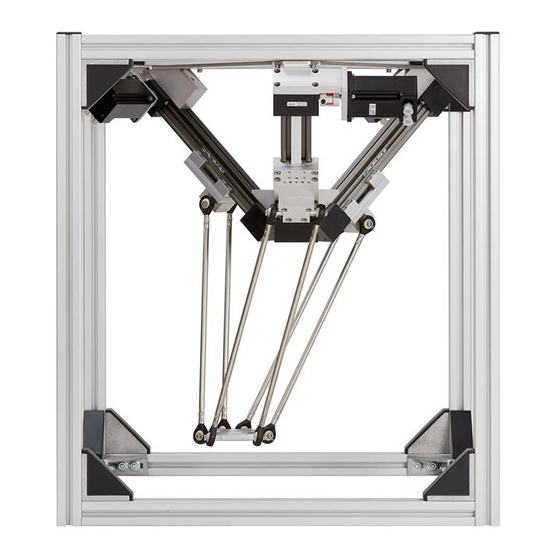
Introduction 3.1. System Overview The robot system consists of four basic components: Delta Robot : the mechanical linear joints, motors and connectors; Robot Controller : Support Module, Steppermotor Driver and DIO Modules; Robot Control Software: control software to execute robot programs; Programming Environment: graphical software to set up robot programs. -
Page 10: Glossary And Abbreviations
3.2. Glossary and Abbreviations Image Name Abbrev. Description igus ® drylin ® Robot Mechanical robot Delta Robot arm including structure, motors and cables Modular Robot Robot Consists of: Controller Controller 1 Support Module 3 or more Stepper Modules ... - Page 11 Emergency Single-channel Stop Button emergency stop Electronic Control Modules Digital Reads 7 digital Input/Output Module inputs on 24 V level. Module Sets 7 digital output channels based on Solid State Relays. Steppermotor Stepper Versions: Driver Module Module Motor Encoder (ME): - high current (HC) - low current (LC)
-
Page 12: Specifications
CPU e.g. Texas Instruments AM3352 Operating system Linux Software TinyCtrl Robot Control Software Interfaces Control of the drives and DIO Modules via the CAN bus Connection to igus ® Robot Control via Ethernet RS232 display connection Programming and Robot Control Software igus ®... -
Page 13: Mechanical Dimensions
3.4. Mechanical Dimensions For more information see the igus ® manual “Technical Documentation robolink ® DP Version”. -
Page 14: Electrical Connections
Electrical Connections 4.1. Overview Figure 4.1: Overview of electrical connections. -
Page 15: Pinout: Stepper Module
4.2. Pinout: Stepper Module Each Stepper Module drives a bipolar stepper motor with Motor Encoders. The encoder signals are evaluated by a line driver (RS422). Signals to each axis travel via three cables: the motor cable, encoder cable and reference switch cable. -
Page 16: Pinout: Support Module
4.3. Pinout: Support Module The Support Module provides 5 V logic voltage, a single-channel emergency stop relay, a SoftStart relay. It feeds the signals into the DIN rail bus system. Supply voltage connector: Pin 1 (left): red 24 V Pin 2: black Pin 3: do not connect -... -
Page 17: Pinout: Digital Input/Output Module
4.4. Pinout: Digital Input/Output Module The DIO Module provides input and output channels, e.g. to operate a gripper valve. The outputs can switch up to 500 mA. The inputs use optocouplers and are compatible to input Voltages between 12 and 24 V. A circuit switched by the output relays must not contain any larger capacitors. -
Page 18: Connect Sensors And Actors To The Dio Module
4.5. Connect Sensors and Actors to the DIO Module The easiest way to connect a programmable logic controller (PLC) is via digital inputs and outputs. Each Robot Controller comes with one DIO Module. This provides 7 inputs and 7 outputs (see Section 4.4). If additional inputs and outputs are required, up to two additional DIO Modules can be integrated, see Section 10.1. - Page 19 4.5.1.1. To Connect a Sensor Pin 1 (GND) of the D-In 1 connector must be connected to GND of the power supply of the sensor. The sensor signal (positive) must be connected to an input pin D-In 1 connector pins 2-4 or D-In 2 connector pins 1-4.the positive side of the sensor has to be connected to VDD of the power supply.
-
Page 20: Option: Control Cabinet
4.6. Option: Control Cabinet The Modular Robot Controller can be ordered in a steel cabinet. The cabinet shields the control from dust, humidity and accidental access. The dimensions of the control cabinet are W x L x H: 600 x 200 x 125 mm Figure 4.4: Control Cabinet, closed. -
Page 21: Option: Embedded Computer
Ethernet Connection ETH0 Connection to PC for Standard Ethernet Primary Ethernet Port programming via IP 192.168.3.11 (next to the USB port) igus ® Robot Control ETH1 Usually none. Can be used to Standard Ethernet Secondary Ethernet Port connect a camera IP 192.168.4.11... - Page 22 The 2 leaded ribbon cable of the Embedded Computer is the RS232 connection for the Operating Panel. One lead is marked black (Lead 1). It is connected via a distribution block to a 9-pin D-Sub connector. Lead 1 (black) D-Sub conn. Orange Lead 2 D-Sub conn.
- Page 23 4.7.3. CAN Connection CAN ribbon cable Establishes the CAN Lead 1: GND (black) (three conductors) connection to the Stepper Lead 2: CAN-L Modules. To be connected to Lead 3: CAN-H the Support Module The 3 leaded ribbon cable of the Embedded Computer is the CAN connection.
-
Page 24: Option: Operating Panel
4.8. Option: Operating Panel The Operating Panel is used to control the Robot via the Embedded Computer. For operating instructions see Section 9. The connection of the D-Sub-9 connector is mating to the D-Sub-9 socket of the Control Cabinet Section 4.7.2. Figure 4.8: Operating Panel with touch screen and 3-axis joystick. -
Page 25: Safety
The components of this robot system are provided with CE marking as requested by the European machinery directive. Responsible for the components are: igus GmbH: robolink DP Robot Arm Commonplace Robotics GmbH: Modular Robot Controller. These CE markings confirm the adherence of these parts of the final machine to the necessary standards. - Page 26 Figure 5.1: Schematic wiring of the safety components with the Support Module.
-
Page 27: Software Installation
Software Installation Backup important data before installing the igus ® Robot Control software. Before updating the igus ® Robot Control software, create a backup of the current version, e.g. by renaming the folder C:\ iRC-igusRobotControl\ to C:\iRC-igusRobotControl_BAK\. 6.1. - Page 28 C:\iRC-igusRobotControl When installing igus ® Robot Control in a Windows program directory like C:\Programs it is possible that igus ® Robot Control can only be started as administrator. The installation usually only takes a few seconds. After finishing the installation, you can start igus ®...
-
Page 29: Licensing
Please do not change the content of the license file, otherwise it will become invalid! The included standard license allows the installation and use of igus ® Robot Control on any number of computers in the company or organization of the licensee. -
Page 30: Installing The Can-To-Usb Driver
When no Embedded Computer has been supplied, a CAN to USB adapter is supplied that connects the Modular Robot Controller and a computer. It requires the appropriate driver. The Robot Control Software is delivered with the PCAN-USB driver from www.peak- system.com, which can also be found igus ® Robot Control installation USB memory stick (directory PCAN-USB-Adapter) or the installation CD of the manufacturer. -
Page 31: Moving The Robot With Irc
Windows software. You can work both online and offline, i.e. with the robot or in simulation (with the robot switched off or disconnected). Figure 7.1: igus® Robot Control user interface. In the upper left corner, the three tabs "File", "Scene" and "Motion" provide access to the main function-sets. - Page 32 Robot, e.g DLE-DR-0001. Figure 7.2: Selecting Robot type of the "File" tab in the "Open project". 7.1.2. Mouse: Navigation and Moving Robot in the User Interface To navigate in the igus ® Robot Control 3D environment, a 3-button mouse is recommended: ...
-
Page 33: Connecting The Robot
Middle button/wheel: o Navigation in the scene to turn the Robot: move the cursor while holding down the middle mouse button. o Mouse wheel: zoom in/out to the current cursor position. Right key: pan The function of the left mouse button can be changed in the "Scene"... -
Page 34: Referencing The Robot
This key is used to reset the error memories of the electronic modules of the Robot Controller. The axis positions are transferred from the real Robot to the simulation environment. The 3D visualization of the Robot should now correspond to the current position of the real Robot. -
Page 35: Moving The Robot With Software Buttons Or Gamepad
7.3.1. Steps to Referencing Start the Robot Controller and igus ® Robot Control. 2. Press the "Connect", "Reset" and "Enable" buttons (Figure 7.3). 3. Click on "Reference" icon (Figure 7.3) in the "Physical robot" ribbon group in the "Motion" tab (or "Reference robot" via "File" tab) to open the referencing window. - Page 36 X, Y, Z, A, B and C. 2. A gamepad is potentially the most intuitive way to move the Robot. Figure 7.7 shows the key assignments. By pressing "Connect Controller", igus ® Robot Control connects to a gamepad.
-
Page 37: Starting Robot Programs
7.5. Starting Robot Programs The robot program must be loaded and started. Load the program: click the "Load" folder icon in the "Current program" ribbon group of the "Motion" tab and select a program. Figure 7.8: Loading a new program. 2. -
Page 38: Digital Inputs And Outputs
After pressing the "Stop" icon, the program starts with the first command when the "Play" icon is clicked again. The "Replay Mode" can be set to: o Single (program stops after a single cycle). o Repeat (program does not stop until "stop" or "pause" is pressed). o Step (program steps line-by-line. -
Page 39: Updating The Software
7.8. Updating the Software Updates of the iRC software can be found on the igus LowCostAutomation website. BackUp: Please rename your old iRC-igusRobotControl folder to e.g. C:\ iRC- igusRobotControl _BAK before starting the installation. This way, you can switch back to the old version in case of doubt. -
Page 40: Programming The Robot With Irc
Programming the Robot with iRC igus ® Robot Control allows the creation of robot programs. The type of programming is called “Teach-In-Programming”, which works as follows: Move the robot manually to the position you want to record Record the position and define how to reach this position (linear/joint motion) Repeat these steps and in between add digital output commands or program flow commands. - Page 41 8.1.1. Changing the Command Sequence To move the command down, click on “Move down”, on “Move up” to move up. It is also possible to use the arrows on the right side of the commands. The Program Editor will prevent commands that would render the structure of a program illegal.
- Page 42 The Program Editor will then replace the position constant in the command with the current position of the Robot. 8.1.3. Current Starting Command It is possible to execute programs command-wise, or to pick a specific command as starting point of a program for debugging purposes. The command that will be executed first, next time the program is started, or –...
-
Page 43: Comments And Information In Programs
8.1.4. Undo and Redo All changes made in the Program Editor can be undone / redone. To undo you can: To redo a previously undone change you can: Press Ctrl+Y. Press Ctrl+Z. Click on the menu item ... - Page 44 8.2.3. Comments The Comment command can be used to include pure descriptions into programs. It has no effect on the robot during execution, its sole purpose is to provide a Description. It is accessible in iRC’s Program Editor through the menu entry “Special”->”Comment:...
-
Page 45: Variables And Variable Access
8.3. Variables and Variable Access Two types of variables are supported in programs for iRC and TinyCtrl: Number variables: these can be used to store integer or floating point numbers Position variables: these can be used to store Cartesian positions and joint positions. - Page 46 “Position constant”: A position variable will be initialized with the constants given under “Cartesian position”, “Joint position” and “External axes”. Depending on the kinematic model of the current robot certain axes may be unavailable. The name of the variable can be set under “Variable”. If a variable with the same name has already been defined its value and type will be overwritten.
- Page 47 8.3.4. Operations on Variables Operations on variables can be performed by using the Math command, which is accessible in iRC’s Program Editor through the menu entries under “Special”->”Variable operation”. “Operand 1” defines the first operand of the operation that is to be performed. It will also be used to store the result of the operation.
- Page 48 8.3.5. Monitoring Variables You can monitor the current values of all defined variables under iRC in the ‘’Programs & Variables’’ tab:...
-
Page 49: Execution Flow
8.4. Execution Flow 8.4.1. Conditional Expressions Conditional expressions can be used in if-then-else commands, conditional loops and as abort conditions in motion commands. The conditional statements can be combinations of digital inputs, global signals, Boolean operations and comparisons. Examples: DIn23 True, if digital input 23 is high ... - Page 50 8.4.2. Stop The Stop command stops the program execution. It is available through the menu entry “Flow”->”Stop”. 8.4.3. Pause The Pause command pauses execution of the program. Execution can later be resumed by the user. It is available through the menu entry “Flow”->”Pause”.
- Page 51 8.4.4. Wait The Wait command allows the robot to wait for a fixed amount of time or until a conditional statement evaluates to true. It is accessible though the menu entries under “Flow”->”Wait” in iRC’s Program Editor. The different modes can by chosen under “Type”: ...
- Page 52 8.4.5. If-then-else The If command branches execution of the program depending on the value of a conditional expression. It is accessible through the menu entry “Flow”-“If…then...else” in iRC’s Program Editor. The conditional expression given under “Condition” must match the syntax described in Section Fehler! Verweisquelle konnte nicht gefunden werden.
- Page 53 8.4.6. Loops The Loop command allows to define execution loops. It is possible to choose between the following types of loops under “Type”: “Condition” The loop will repeat until the conditional expression given under “Condition” evaluates to “True”. It must follow the syntax described in Section Fehler! Verweisquelle konnte nicht gefunden werden.
- Page 54 8.4.7. Matrix Loops The Matrix command is designed to execute loops that allow the robot to perform raster- movements, for example for palletizing tasks. It can be accessed through the menu item “Flow”->’’Loop’’->”Matrix”. The illustration below shows the movement pattern that can be achieved by using the Matrix command.
- Page 55 The block between “Matrix” and “Matrix End” will be executed for each step. The position variable given to “Target” will contain the position of the current target point for the current step. Row and column of the current step will be stored in the number variables given to “Counter X”...
-
Page 56: Motion
8.5. Motion 8.5.1. Abort Conditions An abort condition can be given to any motion command. It is a conditional expression, following the syntax described in Section 8.4.1. During the execution of the motion command the statement is continuously evaluated, and the moment it evaluates to “True” the robot will stop moving. - Page 57 8.5.3. Joint Motion The Joint command moves the robot to a (absolute) target position given in joint coordinates. The resulting motion of the TCP will typically be a curve and not a straight line. The target position can be given in the following ways (choose corresponding “Source”): ...
- Page 58 The Joint command can be accessed in iRC’s Program Editor under the menu entries “Action”->”Joint motion” and “Action”->”Variable motion”->”Joint”. 8.5.4. Linear Motion The Linear command moves the robot to an (absolute) target position given in Cartesian coordinates. The resulting motion of the tool center point (TCP) will follow a straight line. The target position can be given in the following ways (choose corresponding “Source”): ...
- Page 59 “Variable”: The target position is taken from the position variable given to “Variable”. The movement speed is given by “Velocity”. It is measured in mm/s, if it exceeds the maximally allowed movement speed of the robot it will cause a kinematic error during execution.
- Page 60 The following modes of relative motion can be chosen under “Type”: “Joint”: The relative offset is specified in joint coordinates. The movement speed is given by “Velocity”. It is measured in percent of the maximally allowed movement speed for the respective robot axes.
- Page 61 “Linear – Tool”: A linear movement with an offset specified in Cartesian coordinates will be performed. The coordinate system used for the offset are tool coordinates. The movement speed is given by “Velocity”. It is measured in mm/s, if it exceeds the maximally allowed movement speed of the robot it will cause a kinematic error during execution.
-
Page 62: Gripper And Digital Io
8.6. Gripper and Digital IO 8.6.1. Digital Inputs Digital inputs and global signals are accessible as reserved words in conditional statements as expressions in Section 4.1. For global signals these are GSig1, GSig2, … , for digital inputs these are Din1, Din2, … . Depending on the state they will either evaluate to “True” or to “False”. -
Page 63: Camera
You can set the desired aperture, measured in percent, under “Aperture”. A value of 0% represents a fully closed gripper, 100% represents a fully opened gripper. For grippers that can only be either fully opened or fully close the threshold between these states is at 50% aperture. -
Page 64: Stand-Alone Operation With Embedded Computer And The Operating Panel
Stand-alone Operation with Embedded Computer and the Operating Panel To run the robot without a Windows PC connected, the Embedded Computer is necessary. It runs the TinyCtrl software as Robot Control Software. The Embedded Computer allows to jog the Robot Arm (using the Operating Panel), and to replay robot programs. To set up new programs it is connected via Ethernet to a Windows Computer running iRC. -
Page 65: Reset Errors/Enable Robot
9.1. Reset Errors/Enable Robot On the touchscreen display, press the "Enable" button in the upper menu (top right) to get to the Enable page. Now press "Reset": The status changes to "MNE" (Motor Not Enabled) Press "Enable": The status changes to "No Error". "Not ref'd!"... -
Page 66: Referencing
9.3. Referencing To enable an automatic program sequence, the Robot electronics must be referenced. The type of referencing movement depends on the Robot or encoder type. 1. To do this, press the square "Enable" button at the top edge of the display. 2. -
Page 67: Manually Setting The Digital Inputs/Outputs
"Stop" stops the movement. The slider "Override" can be moved to the right to increase the speed of the movement or to the left to decrease it. 9.5. Manually Setting the Digital Inputs/Outputs The digital outputs can be activated and deactivated by pressing the illustrated switches. ... -
Page 68: Organize Programs On The Embedded Control
With time there might be the necessity to re-organize these programs, e.g. to delete some of them. This is possible with the “Manage Programs” icon in the “Motion” tab. Figure 9.2: igus ® Robot Control ribbon with "Manage programs" icon (circled in blue). -
Page 69: Project Configuration
Project Configuration 10.1. Program With “Configure Project / Program” settings, the starting set up can be defined: File: which program to load during startup File logic: which logic program to load during startup. The logic file runs parallel to the main program allowing e.g. -
Page 70: Inputs / Outputs
10.3. Inputs / Outputs With “Configure Project / I/Os” settings, the number of available inputs and outputs can be configured and renamed. The corresponding names will show up in the Input/Output tab. Figure 10.3: Configuration of Inputs / Outputs in the backstage area. For the robolink robot control, the ”Base I/O”... -
Page 71: Virtual Box
10.4. Virtual Box The “Configure Project / Virtual Box’’ settings allow to restrict the motion range of the robot arm. These restrictions are monitored both, in linear and in joint motion. This functionality assists to avoid mechanical damages. It is not a functionality rated for personal safety! Figure 10.4: Robot Arm violating the virtual box. -
Page 72: Interfaces Configuration
Interfaces Configuration 12.1. Cameras The iRC software has built-in support for receiving target positions from cameras. Currently the IFM O2D is supported. Figure 12.1: Camera configuration dialog. The work piece position reported by the camera can be accessed with the “Camera” command in the robot program, see Section 8.7. -
Page 73: Plc Interface
Computer and igus ® Robot Control on the Windows PC communicate via the CRI interface. This interface makes it possible to combine the igus ® Robot Control functions with application-specific algorithms, such as a teleoperation system or a database. The CRI... -
Page 74: Troubleshooting
C:\iRC-igusRobotControl\. 13.2. Online Tool - Fault Identification and Recovery Via the igus support landing page you have access to web pages that allow to: Identify a problem based on user observations Propose solutions to the problem... -
Page 75: Configuration Of The Stepper Modules
13.3. Configuration of the Stepper Modules The operating parameters of the Stepper Modules, particularly the motor currents, can be adapted to the application. The Stepper Modules are delivered with a standard parameterization for the specific Robot. Normally no change of the parameters is necessary. If the Robot is to be operated at high loads or speeds, the motor currents can be increased. -
Page 76: Calibration Of The Robot
The Current Scale parameters define the max. current during normal operation (Load), during the start-up phase (Start), at standstill (Idle) and during referencing (Ref). o The Stepper Module uses Trinamic CoolStep technology to adjust the motor current between these values and a lower limit value, which is a fraction of the Current Scale value. -
Page 77: Error Codes
Error Codes The Robot Controller provides several status information: Status LEDs on the Electronic Modules. igus ® Robot Control status information, received via CAN status bytes. 13.5.1. Status LED of the Electronic Modules Support Module: Green LED on:... - Page 78 13.5.2. CAN-Bus and iRC Status Information Bit in Error Meaning Measures error byte Bus dead The CAN-Bus is not available. Check the plug connections of the Reasons are missing power power supply and the CAN line. supply or missing plug Restart the control computer.
Need help?
Do you have a question about the Drylin Delta and is the answer not in the manual?
Questions and answers