Advertisement
Quick Links
Advertisement

Subscribe to Our Youtube Channel
Related Manuals for Dogtra QL2


Summary of Contents for Dogtra QL2
- Page 1 Owner’s Manual ASSEMBLY INSTRUCTIONS Available for use with the Dogtra RR DELUXE...
- Page 3 QL2 launcher contents Left Plate Launcher Basket Bolt ×4 Nut ×4 Spring ×2 Launcher Right Hex Wrench Rubber Mesh Plate Wrench ×1 Rod ×1 Cap ×2 CAUTION SHARP EDGES Failure to follow this caution may result in personal injury. Sheet metal parts may have sharp edges or burrs. Use care and wear appropriate...
- Page 4 1. Mounting the left plate Left Plate Find the “L” mark on the left plate and the launcher basket to match the pieces together.
- Page 5 As shown in the picture, align the left plate with the groove on the launcher basket. Lower it downward in an upside down L shape to combine with the main body. CAUTION SHARP EDGES Failure to follow this caution may result in personal injury. Sheet metal parts may have sharp edges or burrs. Use care and wear appropriate protective clothing, safety glasses, and gloves when handling parts.
- Page 6 2. Mounting the right plate Right Plate Find the “R” mark on the right plate and the launcher basket to match the pieces together.
- Page 7 As shown in the picture, align the right plate to the groove at the bottom of the launcher basket. Insert the plate and lower it downwards to combine both pieces. CAUTION SHARP EDGES Failure to follow this caution may result in personal injury. Sheet metal parts may have sharp edges or burrs. Use care and wear appropriate protective clothing, safety glasses, and gloves when handling parts.
- Page 8 3. Fastening the pieces Use the nuts and bolts to fasten the plates and basket together. Tighten so that there is no empty Top: Nut space between the bolt and nut. Bottom: Bolt Bottom...
- Page 9 Put the hex wrench rod all the way Place the bolt from the bottom to Use the enclosed hex wrench to into the hex wrench. top and hold in place. Make sure fasten together. that the square portion of the bolt *You can apply some force to is properly fitted into the square tighten securely.
- Page 10 4. Left plate guide bar installation Insert the left guide bars on the launcher mesh into the holes on the left plate. *Note the difference in the shape of the bar from the right side. Insert both sides of the left guide bar into the holes on the left plate.
- Page 12 5. Right plate guide bar installation Insert the right guide bars on the launcher mesh into the holes on the right plate. *Note the difference in the shape of the bar from the left side. Insert one side of the right guide bar at a time into the holes located on the right plate.
- Page 13 Place the rubber caps on the end of the right guide bar.
- Page 14 6. Right spring installation Caution The springs should be installed only on the left plate. Spring② Spring① Wingnut Spring① 1. Use the spring① side to hook 2. Put the spring on the guide 3. Move the launcher mesh to onto the guide bar. bar first and then work your the right side.
- Page 15 Spring② 4. Use the spring② side to hook 5. The right spring installation is Warning! onto the wingnut. complete. If the hook is not fully inserted into the nut, the spring It will require some force to put may fall out and cause injury. the spring into the hole on the wingnut.
- Page 16 7. Left spring installation Spring① Spring② Wingnut Spring① 2. Put the spring on the guide 3. Move the launcher mesh to 1. Use the spring① side to hook bar first and then work your the left side. onto the guide bar. way to the wingnut.
- Page 17 Spring② 4. Use the spring② side to hook 5. The left spring installation is Warning! onto the wingnut. complete. If the hook is not fully inserted into the nut, the spring It will require some force to put may fall out and cause injury. the spring into the hole on the wingnut.
- Page 18 8. Adjusting spring tension settings Low launch Mid launch High launch...
- Page 19 Warning! Use the included hex wrench to Make sure both springs are adjust the wingnut. completely in place. If not Clockwise: high launch placed correctly, the springs Counterclockwise: low launch may fall off and cause injury. When the wingnut goes up, the launch is low. When the wingnut goes down, the launch is high.
- Page 20 9. Setting up the basket Hold both sides of the launcher Press the launcher mesh in. Move the release lever inwards. mesh and place inside the basket.
- Page 21 ② ① Make sure the release lever goes Move the latch in the direction of The setup is now complete. in securely under the latch. the arrow to go over the release lever. Warning! Make sure that the release lever is underneath the latch shown in step 2 above. If it not securely set, the basket may pop and cause injury.
- Page 22 10. Using the safety pin Find the red safety pin attached Insert the safety pin into the The safety pin is now in place. to the basket. middle hole on the latch.
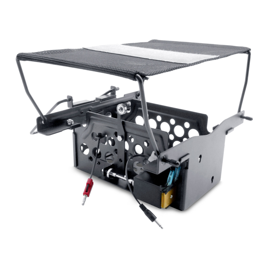
- Page 23 If the final product looks like above, the setup is complete.
Need help?
Do you have a question about the QL2 and is the answer not in the manual?
Questions and answers