
Subscribe to Our Youtube Channel
Related Manuals for Nivus NivuFlow 550


Summary of Contents for Nivus NivuFlow 550
- Page 1 F L O W Instruction Manual Flow Measurement Transmitter for Radar Sensors NivuFlow 550 Firmware Revision: 2.09 Original Manual: German...
-
Page 2: Copyrights And Property Rights
Copyrights and property rights Copyrights and property rights This document and its contents are proprietary to NIVUS GmbH and are not to be reproduced or copied without the express written permission of NIVUS GmbH. Violations oblige to compensation. Important Note This instruction manual may exclusively - even in parts - be copied or translated in any other way with the express written consent of NIVUS GmbH. -
Page 3: Modifications
Instruction manual NivuFlow 550 Modifications Rev. Modifications Person in Date charge First version 12.04.2017 page 4 rev. 00 / 12.04.2017... -
Page 4: Table Of Contents
Table of contents Table of contents COPYRIGHTS AND PROPERTY RIGHTS MODIFICATIONS GENERAL About this manual ...............11 Applicable documentation ............11 1.2 Signs and definitions used ............11 Abbreviations used ...............12 Connections and user elements ..........12 Power supply ................12 NivuFlow control elements ............13 Tasks of control elements ............. - Page 5 Instruction Manual NivuFlow 550 PRODUCT SPECIFICATION Product construction and overview ..........20 Dimensions of enclosure .............. 20 Connectable sensors ..............21 9.3 Device identification ..............21 10 Specifications ................23 11 Configuration ................24 11.1 Device Types ................24 11.2 Delivery ..................24 11.3 Reception inspection ..............24 11.4 Storing ..................25...
- Page 6 Table of contents 15.1.1 Clamps for Protective Conductor Terminal and AC Supply 30 15.1.2 Power supply DC ..............30 15.1.3 Power supply AC ..............30 15.1.4 Relays .................31 16 Installation of sensors ..............32 16.1 Sensor Installation Principles ............32 16.2 Preparations for Sensor Installation ..........32 17 Sensor Connection ..............33 17.1 Cable and cable lengths for sensor connection ......
- Page 7 Instruction Manual NivuFlow 550 22 Parameter Functions ..............49 22.1 Main Menu ..................49 22.2 Functions Top Menu Level ............49 22.2.1 Application Menu ..............49 22.2.2 Data Menu ................50 22.2.3 System Menu ..............51 22.2.4 Communication Menu ............51 22.2.5 Display Menu ..............52 22.2.6...
- Page 8 Table of contents 24.2 Day Totals ..................82 24.3 USB-Transfer ................83 24.4 Data Memory (Internal) ..............88 25 System ..................89 25.1 Information ..................89 25.2 Language Settings ................90 25.2.1 (Operation) Language ............90 25.2.2 Date Format ................ 90 25.2.3 Units ...................90 25.2.4 Memory Units ..............
- Page 9 Instruction Manual NivuFlow 550 29.3 Display Velocity ................106 29.3.1 Menu Settings (Velocity) ........... 107 29.3.2 Menu Diagnostics (Velocity) ..........107 29.4 Display Temperature and Sum ........... 108 29.5 Display Trend/Hydrograph ............108 DIAGNOSIS 30 Basics of Diagnosis Menus ............109 31 Diagnosis h-Sensors ..............110 32 Diagnosis v-Sensors ..............
-
Page 10: General
KEEP IN A SAFE PLACE FOR LATER REFERENCE! This instruction manual is an original instruction for the flow measurement transmitter NivuFlow 550 and is for the intended use of the device. This manual is oriented exclusively to qualified expert personnel. -
Page 11: Abbreviations Used
Instruction Manual NivuFlow 550 Abbreviations used Colour code for wires, single conductors and components. The abbreviations of colours, wire and components follow the international colour code accord- ing to IEC 757. black transparent blue white GNYE green/yellow green yellow brown... -
Page 12: Nivuflow Control Elements
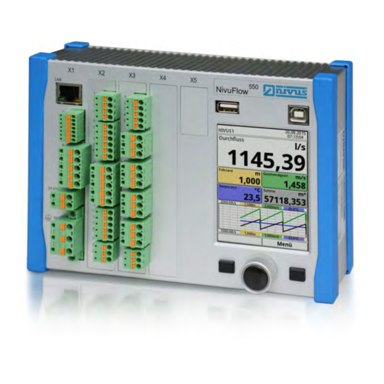
General NivuFlow control elements The NivuFlow is operated completely in dialogue mode supported by the graphs on the dis- play. To select individual menus and sub-menus use the rotary pushbutton as well as the both function keys. Graphic display Left function key Rotary pushbutton Right function key Fig. -
Page 13: Interfaces
Instruction Manual NivuFlow 550 Right function key They key is used to confirm value entries (via numeric keys or letter keys). For some parameters the right function key can be used as >TAB<. This TAB function is active only with the settings below: •... -
Page 14: Safety Instructions
Safety Instructions Safety Instructions In general: Used symbols and signal words Valuation of the accident level The general warning symbol indicates the risk of personal injuries or death. In the text section the general warning symbol is used in conjunction with the signal words described below. -
Page 15: Warning Notices On The Product
Safeguards and Precautions Working with NIVUS instruments requires to observe and to follow the safety measures and precautions below generally and at any time. These notes and warnings will not be repeated for each description within the document. -
Page 16: Liability Disclaimer
All operations on the device which go beyond installation or connection measures in principle shall be carried out by NIVUS staff or personnel authorised by NIVUS due to reasons of safety and guarantee. -
Page 17: User's Responsibilities
The combination of NivuFlow and the iXT Ex Separation Interface is adjusted solely to NIVUS correlation sensors regarding the intrinsically safe system review according to EN 60079-25. In the event of using sensors by third-party manufacturers the operator shall carry out a... -
Page 18: Personnel Requirements
Safety Instructions Personnel requirements Installation, commissioning and maintenance shall be executed only by personnel meeting the demands as follows: • Expert personnel with relevant training an appropriate qualification • Personnel authorised by the plant operator Qualified personnel within the context of this documentation or the safety notes on the product itself are per- sons who are sufficiently familiar with installation, mounting, starting up and operation of the product and who have the relevant qualifications for their work;... -
Page 19: Product Specification
X1 Power supply, air ultrasonic sensor connection via RS485, Interfaces (LAN and Bus) X2 Digital in-/outputs, 1x RS485 and analog in-/outputs Fig. 9-1 Device setup NivuFlow 550 Dimensions of enclosure Fig. 9-2 Dimensions of the transmitter NivuFlow 550 page 20 rev. 00 / 12.04.2017... -
Page 20: Connectable Sensors
Product specification Connectable sensors The image below provides an overview on the connectable sensors. Radar sensor OFR Ultrasonic level sensor, Type OCL-L1 (option) i-Series sensor NMI0 Fig. 9-3 Overview of connectable sensors Device identification The instructions contained within this manual are valid only for the type of device specified on the title page. - Page 21 Instruction Manual NivuFlow 550 Nameplates Fig. 9-4 Nameplate AC version Fig. 9-5 Nameplate DC version page 22 rev. 00 / 12.04.2017...
-
Page 22: Specifications
- 1x 4...20 mA for external level (2-wire probe) Inputs - 1x RxTx-Bus for NIVUS air-ultrasonic sensor Type OCL - 1x 0/4...20 mA with 12 Bit resolution for external level, external controller setpoint and data storage of external units, accuracy ±0,4 % of measur-... -
Page 23: Configuration
Furthermore a written report shall be sent to NIVUS GmbH in Eppingen. Incomplete deliveries shall be reported in writing either to your local representative or directly to the NIVUS head office in Eppingen within two weeks. Note Mistakes cannot be rectified later! page 24 rev. -
Page 24: Storing
Do not expose the system to heavy shocks or vibrations. Use the original packaging for trans- port. 11.6 Return In case of a required reshipment return the unit at customer cost to NIVUS GmbH in Eppingen using the original packaging. Insufficiently franked shipments will not be accepted! 11.7... -
Page 25: Functional Principle
NivuFlow 550 Functional Principle 12 Operating Range The NivuFlow 550 is a non-portable measurement system for flow measurement. The equip- ment is conceived preferably for measurements in clear to heavily polluted aqueous liquids with various compositions. The system can be used in part filled flumes, channels and pipes featuring various shapes and dimensions. -
Page 26: Level Measurement
(e. g. by using an i-Series sensor). It is possible to directly connect 2-wire sensors supplied by the NivuFlow 550 (e. g. NivuBar, NivuCompact, i-Series sensor). A 4…20 mA signal provided by an external transmitter (such as 4…20 mA from NivuMaster) can be used as well. -
Page 27: Installation And Connection
It can be also installed in field enclosures or similar. Due to the protection degree, NivuFlow 550 is not suitable to be installed directly on site without protective measures. To do so, use the optionally available field enclosure by NIVUS. -
Page 28: Fastening The Transmitter
Installation and Connection Ü Â Observe the permissible ambient temperature. Ü Â Do not expose the transmitter to strong vibrations or mechanical shocks. At the mounting place always avoid: • corrosive chemicals or gases • radioactive radiation • direct installation close to footpaths or travel ways 14.3 Fastening the Transmitter Note... -
Page 29: Power And Relay Connections
Instruction Manual NivuFlow 550 How to connect the sensors can be found starting at page 33, connecting the power supply is described on page 41. 15.1 Power and Relay Connections 15.1.1 Clamps for Protective Conductor Terminal and AC Supply WARNING... -
Page 30: Relays
Installation and Connection 15.1.4 Relays The reliability of the switching contact deteriorates if the minimum switching current is lower than specified. Observe the connection and switching specifications of the relays (see chapter „10 Specifications“). WARNING Danger from electrical current – Measures to prevent accidental contacts Contact protection according to the requirements as specified in EN 61010-1:2010 is not guaranteed in the event of relay voltages >... -
Page 31: Installation Of Sensors
Instruction Manual NivuFlow 550 16 Installation of sensors This chapter describes the sensors to be used and the usual places of application. The instal- lation of individual sensor types is described in greater detail in the according installation instructions. Note During mounting works ensure compliance with all regulations on safety at work. -
Page 32: Sensor Connection
17.1 Cable and cable lengths for sensor connection Between sensor and transmitter (direct connection non Ex): For the complete distance between the NIVUS sensors and transmitter type NivuFlow 550 use the specified cable of NIVUS: • LiYC11Y 2x1,5 mm² + 1x2x0,34 mm² + PA... -
Page 33: Sensor Connection At Nivuflow
Instruction Manual NivuFlow 550 NivuFlow max. 250 m OCL-L1 A2Y(L)2Y 10 • 2 • 0,5 mm² LiYC11Y 2 • 1,5 mm² + 1 • 2 • 0,34 mm² max. 150 m Fig. 17-2 Connecting iXT to NivuFlow via telecommunications cable The signal cable is not suitable for direct and permanent installation in ground. - Page 34 Installation and Connection BK (shield, no earth) outer shield 10 V supply + LIYC 11Y 2 • 1,5 mm² UE-GND + 1 • 2 • 0,34 mm² RxTx - max. 150 m RxTx + Fig. 17-4 Connection radar sensor, type OFR Level via 2-wire sensor The level measurement can also be carried out by a 2-wire sensor (NivuBar, NivuCompact 2-wire echo sounder or similar) which is supplied by the NivuFlow.
-
Page 35: Overvoltage Protection
For effective protection of the NivuFlow transmitter it is necessary to protect power supply as well as mA-output using overvoltage protection devices. NIVUS recommends surge arrestors types EnerPro 220Tr, EnerPro 24Tr (for 24 V DC) for the mains supply, as well type DataPro 2x1 24/24Tr for mA-inputs and mA-outputs. - Page 36 Installation and Connection NivuFlow EnerPro 2x1 - 24 V min. 1,5 mm² Fig. 17-8 Overvoltage protection for power supply DC outer shield supply + DataPro UE-GND 2x1 12 V/12V 11mTr (N) RxTx - OCL-L1 min. 1,5 mm² RxTx + SonicPro 3x1 24 V/24V min.
- Page 37 2x1 12 V/12V 11mTr (N) RxTx - min. 1,5 mm² RxTx + Fig. 17-12 Overvoltage protection iXT to NivuFlow 550 Note • The minimum wire cross section is 1.5 mm² (not for strands). • The maximum permissible cable length is 1 m.
-
Page 38: Transmitter Connection
Installation and Connection 18 Transmitter Connection 18.1 Connection to the Terminal Blocks All NivuFlow transmitters are equipped with push-in tension clamp terminals. The use of these push-in tension clamp terminals enables an easy pre-installation of the transmitter. This allows verifying individual sensors, input and output signals etc. as well as easy transmit- ter replacement if required. -
Page 39: Connection Diagrams
+12 V shield RxTx - supply + RxTx + +24 VDC RxTx - 0 VDC RxTx + AI1 (HART) GND AI1+2 +AO1 +AO2 GND AO1+2 Fig. 18-1 General connection diagram - NivuFlow 550, type R1 page 40 rev. 00 / 12.04.2017... -
Page 40: Switching On Voltage Supply
Installation and Connection 18.2 Switching on voltage supply Depending on the type of NivuFlow 550 used the unit can be powered with 100...240 V AC (-15 / +10 %) or with 10...35 V DC. 24 V DC connection 230 V AC connection Fig. - Page 41 Instruction Manual NivuFlow 550 Fig. 18-3 230 V AC connections of power supply Fig. 18-4 DC connections of power supply page 42 rev. 00 / 12.04.2017...
-
Page 42: Operation Start-Up
Operation start-up Operation start-up 19 Notes to users Before connecting and operating the NivuFlow the instructions below shall be followed. This instruction manual contains all information required for the setting of parameters and for the use of the instrument. The manual is intended for qualified personnel. Appropriate knowledge in the areas of measurement systems, automation technology, control engineering, information technology and wastewater hydraulics are preconditions for putting the NivuFlow into operation. -
Page 43: Operation Basics
Instruction Manual NivuFlow 550 20 Operation Basics The complete operation of the NivuFlow is handled via control elements (see chapter „2.2 NivuFlow control elements“). Two control buttons and one rotary pushbutton are available for the setting of parameters and to input required data. -
Page 44: Use/Entry Using The Letter Block
Operation start-up The transmitter in the background operates with the settings which have been entered at the beginning of the parameter setting. The following request is prompted on the display not before the current parameter setting has been finished and confirmed. Fig. -
Page 45: Use/Entry Using The Numeric Keypad
Instruction Manual NivuFlow 550 Note The use of the key pad is explained here one-time. Later in the manual you will be prompted to enter designations or names following this explanation. A shift key can be found at the bottom left of the keypad (Fig. 20-4 no. 3). -
Page 46: Revision Of Parameters
Operation start-up 20.5 Revision of parameters Ü Â Incorrect entry can be deleted letter by letter or digit by digit by pressing the back button: 1. Open the keypad. 2. Turn the rotary pushbutton until you get to the >back arrow< (back button). 3. -
Page 47: Setting Parameters
Instruction manual NivuFlow 550 Setting Parameters 21 General Programming As a principle modified parameters will not become effective before they have been saved. The transmitter will verify whether parameters have been modified while exiting any menu. Subsequently you will be prompted to decide if you wish to save the modified parameters. -
Page 48: Parameter Functions
Setting Parameters 22 Parameter Functions 22.1 Main Menu The transmitter parameters can be set using a total of six setup menus within the first menu level. Individual menus and the according submenus are explained in greater detail starting in chapter „23 Description of Parameters“. Fig. -
Page 49: Data Menu
Instruction manual NivuFlow 550 Within this menu diagnostic options for the items below are available: • Sensors • Inputs and outputs • Overall system The diagnostic options are explained in chapter „Diagnosis“ starting at page 109. The following parameters can be set or modified in the >Application< menu: •... -
Page 50: System Menu
Setting Parameters 22.2.3 System Menu Fig. 22-4 System Menu The >System< menu contains information on the transmitter: • Article No. • Firmware version • Serial No. Furthermore the settings/adjustments below are available: • Set language • Set units • Adjust date and time •... -
Page 51: Display Menu
Instruction manual NivuFlow 550 This menu comprises the settings for the communication of various communication interfaces with other communication systems: • TCP/IP • Web server (in preparation) • HART (in preparation) • Modbus 22.2.5 Display Menu Fig. 22-6 Display Menu This menu permits to adjust the backlight settings as well as to adjust the settings of the five output fields of the main screen, if required. -
Page 52: Description Of Parameters
Setting Parameters 23 Description of Parameters 23.1 Setting the Measurement Place Parameters (Application Menu) The >Measurement Place< submenu is one of the most important basic menus when it comes to parameter setting. The following basic settings are required to set the parameters of the measurement place: •... -
Page 53: Channel Profiles
Instruction manual NivuFlow 550 23.1.2 Channel Profiles The transmitter provides a great number of standard canal profiles mainly used in practice to choose from. Since special shapes can be found particularly in older channel systems the transmitter moreover allows entering the dimensions of symmetric and asymmetric channels specifying height/area figures into a table. - Page 54 Setting Parameters Fig. 23-3 Example of a channel profile menu Pipe This shape is suitable for round pipes. The selection can be used for half shells featuring a filling level of 50 % as well. Deformed pipes featuring an asymmetric height/width ratio can be set using the ellipsoid shape.
- Page 55 Programming water bed parameters requires thorough knowledge and experience in oper- ating the NivuFlow 550 as well as in hydrological conditions. We recommend programming to be implemented by the NIVUS commissioning service or an expert company authorised by NIVUS. For this profile the reference point/zero point must be defined by the user. Mostly the maximum filling level or the water surface on one side of a bank or a canal is determined as zero point.
- Page 56 Setting Parameters Fig. 23-4 Profile Parameters with Height-Width (sym.) Note A scale drawing is required to set the parameters of the channel. Ü Â Procedure: 1. Draw a vertical auxiliary line through the channel centre on the scale drawing. 2. Draw horizontal auxiliary lines through the distinctive points where the profile changes.
- Page 57 Instruction manual NivuFlow 550 Ü Â Procedure: 1. Draw a vertical auxiliary line from the lowest point of the channel to the top on the scale drawing. 2. Use this line as start to draw horizontal auxiliary lines through the distinctive points where the profile changes to the left and to the right.
-
Page 58: Sludge Level
Radar: • Average value • COSP Default setting: "COSP". NIVUS strongly recommends to maintain the setting since it provides the most accurate results. Remarks on Options COSP: • COSP denotes a correction factor for flow measurements and considers the channel parameters set as well as the resulting changes of the flow behaviour. -
Page 59: Low-Flow Suppression
Instruction manual NivuFlow 550 23.1.5 Low-Flow Suppression This parameter is to suppress very low movements or apparent flow volumes. The main area of use is the measurement of discharge volumes in permanently filled structures. Ü Â Tick >Active<. One more input option opens. Enter here the positive value you wish to suppress in case of lowest discharge. -
Page 60: Damping
Setting Parameters 23.1.6 Damping This menu permits to modify the damping of display and analog output in seconds. The damping relates to all level and flow velocity values available as input values. Individual values cannot be selected and damped differently. All measurement values are saved covering the selected period and a floating average value is created for each individual measurement value. - Page 61 Possible 0/4...20 mA-signals from an external transmitter such as NivuMaster or MultiRanger can be activated here too. i-Sensor • Connect ultrasonic i-Series sensors by NIVUS here. Connection is carried out via the HART interface. • NIVUS Air-Ultrasonic Level measurement from top down using an air-ultrasonic sensor type OCL-L1 or DSM-L0.
-
Page 62: Definition Of Measurement Ranges
Setting Parameters • Fixed Value This selection is conceived for permanently full pipes and channels. Level measure- ment is not required for such applications. The constant filling level is set as fixed value and then used by the system to calculate the flow rate. This parameter can be used as support for initial start-up or for test purposes without having level values available. - Page 63 Instruction manual NivuFlow 550 Fig. 23-11 Representation of programming sections A level sensor can be assigned to each one of the programming sections (see Fig. 23-9). The transmitter will assign the sensors to the appropriate programming section automatically. The assignment depends on the channel shape set before.
- Page 64 Setting Parameters In the i-Sensors menu tick iXT/MPX as soon as the i-Sensor is connected using the HART interface of an iXT. Fig. 23-13 Programming i-Sensor Important Note If the i-Sensor is connected via a type iXT Ex Separation Module it is necessary to enable the use of iXT/MPX in Main Menu/Connections prior to setting the sensor type.
-
Page 65: Setting Parameters In V-Sensors Menu
Profiles“). 23.3.1 Number of Flow Velocity Sensors It is possible to connect more than on flow velocity sensor to the NivuFlow 550 transmitter. The number of connectable sensors depends on the transmitter type: • NivuFlow 550 type R1 – one flow velocity sensor Fig. - Page 66 Setting Parameters 2. Turn the rotary-pushbutton until >Mounting Height< is active. 3. Enter the measured distance here. Default setting: unit METER. Fig. 23-16 Setting the mounting height Installation Direction This particular parameter is used only for special applications. Default setting: sensor installation direction always >positive< (measuring against the flow direction).
-
Page 67: V-Minimum And V-Maximum
Default setting: 57 600 baud. NIVUS strongly recommends to maintain this setting. The radar sensor is calibrated to the standard baud rate of 57 600 baud. The measurement may be massively impaired as soon as this standard setting is modified. -
Page 68: Inputs And Outputs (Analog And Digital)
Setting Parameters 23.4 Inputs and Outputs (analog and digital) This menu is to define the functions of the analog as well as digital inputs and outputs. Fur- ther parameters such as measurement ranges and output spans, offsets, limit values, error responses etc. - Page 69 Instruction manual NivuFlow 550 Currently the analog inputs can be used only for external readings (such as temperature in °C). The transmitter hence can be utilised as an extra data logger for readings from other systems. This, however, does not affect the transmitter’s functionality as flow meter.
-
Page 70: Analog Outputs
Setting Parameters 23.4.2 Analog Outputs The number of analog outputs depends on the instrument type: • Type R1 = two analog outputs The available analog outputs are shown in the top right corner of the display. The analog outputs can be selected successively by pressing the right-hand control key >Tab<. - Page 71 Instruction manual NivuFlow 550 • Sludge level In applications measuring volumes from top down by using a float, an external or an OCL sensor for level detection as well as a water-ultrasonic sensor at the same time, it is possible to determine and to output the sludge level from the difference between both level sensors considering the depth of immersion.
-
Page 72: Digital Inputs
Setting Parameters Fig. 23-26 Output range/output span/error response 23.4.3 Digital Inputs The number of digital inputs depends on the instrument type: • Type R1 = two digital inputs The available digital inputs are shown in the top right corner of the display. The digital inputs can be selected successively by pressing the right-hand control key >Tab<. - Page 73 Instruction manual NivuFlow 550 • Runtime The system detects and saves the duration of the oncoming signals on the digital input. Such records are used e. g. for the runtimes of pumps or other units. If this function is selected the logic can be additionally adjusted as follows: non-inverting digital input ƒ...
-
Page 74: Digital Outputs
Setting Parameters 23.4.4 Digital Outputs The number of digital outputs depends on the instrument type: • Type R1 = two digital outputs The available digital outputs are shown in the top right corner of the display. The digital outputs can be selected successively by pressing the right-hand control key >Tab<. The selection is shown as clear text message in the top left corner of the display. - Page 75 Instruction manual NivuFlow 550 • Limit Contact Flow Set one flow limit value for >Threshold On< and >Threshold Off< each. Exceeding this flow limit value will issue a digital signal. This digital signal will be reset as soon as the value falls below the second flow limit value = hysteresis function to avoid output flutter.
- Page 76 Setting Parameters The sedimentation level can be calculated from the difference between both level sensors. Here the immersion depth of the water-ultrasound must be taken into account. Observe: Soft sludge levels possibly do not reflect ultrasonic signals. In such a case the sedi- mentation level cannot be calculated.
-
Page 77: Diagnosis
Instruction manual NivuFlow 550 • Modbus Slave The digital output can be used via the Modbus for the controlled output of signals from other systems. Fig. 23-33 Logic options 23.5 Diagnosis The diagnosis menu is described in chapter „Diagnosis“ starting at page 109. -
Page 78: Data Parameter Menu
Setting Parameters 24 Data Parameter Menu Fig. 24-1 Data menu 24.1 Trend The trend graph is a representing recorder function. Once you have selected the trend graph you can access previously saved (historic) measurement data. Date / time selection Graph range Scaling max. - Page 79 Instruction manual NivuFlow 550 4. Repeat you entry until the desired time (day, month, year, hour, minute) is specified completely. 5. Confirm your entry with the right function key. Date and time will be accepted. The readings are shown in the display depending on the date and the period selected (Fig.
- Page 80 Setting Parameters Representation: • The range of representation ends exactly 4 hours later on the right side. • This representation is divided by three vertical help lines too. The distance between the lines is one hour. Use the >Browse< function to move backwards and forwards within this screen in steps of 4 hours.
-
Page 81: Day Totals
Instruction manual NivuFlow 550 24.2 Day Totals This is where the flow totals can be viewed in a table. Each value represents a period of 24 hours. Fig. 24-3 Day Totals A maximum of 100 totals (= 100 days) is stored. Starting with value 101 always the oldest value will be overwritten (ring memory). -
Page 82: Usb-Transfer
Setting Parameters Total day 4: total covering 24 hours Power failure Power supply restored Fig. 24-4 Totalising scheme • The totalising period is set to the period between 00:00 o’clock and 24:00 o’clock as per default. This means that the day totals are always created between 00:00 o’clock and 24:00 o’clock. - Page 83 Instruction manual NivuFlow 550 Fig. 24-5 Selection submenu The transmitter is equipped with an internal data memory. Portions of your measurement data or the complete memory contents can be transmitted to USB stick. Within this section it is possible to specify the desired period of transmission.
- Page 84 ƒ and digital inputs Average flow velocities from v-sensors 1, 2 and 3 (if used) ƒ Parameter values for the NIVUS-specific velocity evaluation method >COSP< ƒ Trigger and hydraulic qualities of v-sensors 1, 2 and 3 (is used) ƒ •...
- Page 85 Instruction manual NivuFlow 550 The >Compress< function makes sense only when large data sets are to be transmitted. In such cases the selected files are zipped as ".gz" files. The files can be unzipped again by using the free "7-ZIP" software application.
- Page 86 Setting Parameters Fig. 24-8 Save parameters/format USB Ü Â You can convert unformatted or incorrectly formatted USB sticks into the correct format directly on the instrument: 1. Turn the rotary-pushbutton until >Format USB-Stick< is highlighted blue. 2. Press the rotary-pushbutton to format the plugged USB stick. >SUCCESSFUL< will appear in the display as soon as the stick has been formatted.
-
Page 87: Data Memory (Internal)
Instruction manual NivuFlow 550 24.4 Data Memory (Internal) This submenu can be used to modify the storage cycle and to erase the internal data memory. Fig. 24-9 Data memory Options for the storage cycle: • 30 s • 1 min •... -
Page 88: System
Setting Parameters 25 System 25.1 Information Fig. 25-1 System submenu/system information This is a read-only menu and contains the instrument information below: • Serial number and article number • MAC address • Firmware version of the transmitter Furthermore you can find here the following information on the activated flow velocity and level sensors: •... -
Page 89: Language Settings
Instruction manual NivuFlow 550 25.2 Language Settings The following settings can be adjusted in this menu: • (Operation) Language • Date format • Units of measurement values Here it is possible to distinguish between indicated and saved measurement values. Fig. 25-2 Language settings/language/date format 25.2.1... - Page 90 Setting Parameters Fig. 25-3 Units system Units system Available units: • Metric • English • American The adjustable units depend on the selected units system: • In metric system - e. g. liter, cubic metre, cm/s etc. • In English system - e. g. ft, in, gal/s, etc. •...
-
Page 91: Memory Units
Instruction manual NivuFlow 550 25.2.4 Memory Units Ü Â When adjusting the >Memory Units< proceed right as described under >Units<. Fig. 25-4 Memory units In the >Memory Units< section the detected measurement values are converted and saved according to the selected unit. -
Page 92: Time/Date
Setting Parameters 25.3 Time/Date This submenu is used to change the system time of the transmitter and the current date. This function is required to change over summer and winter time, after power failure or if the internal buffer battery should fail. If the transmitter is operated for a long period the internal clock may deviate. -
Page 93: Error Messages
Fig. 25-8 Service Service Level The service level is reserved to the NIVUS customer service as well as authorised expert companies and hence is protected by a special service password. System-relevant modifications and special settings for particular applications can be adjusted here. -
Page 94: Change (System) Password
Change (System) Password Default password: "2718" NIVUS recommend to change this password in order to protect the system from unauthorised access. You are free to select any password with a maximum length of ten digits. For your own safety we recommend to share your password only with authorised individuals. -
Page 95: Parameter Reset
Furthermore the network integration can be set up here as well. The details will not be explained here. If you should not have the required IT skills we recommend to leave such tasks to IT specialists or the NIVUS commissioning personnel. Fig. 26-1... - Page 96 The transmitter can currently not be used as HART slave for follwing systems. Modbus It is possible to integrate the transmitter into other systems via Modbus. The Modbus protocolis available upon request if required. Contact the NIVUS GmbH head- quarters in Eppingen. Fig. 26-2...
-
Page 97: Display Parameters Menu
Adjust the backlight to the ambient conditions. Avoid setting the display too bright. In order to extend the display life NIVUS recommend to enable the automatic display dimming option here (dim light). The display will dim automatically if it has not been used for a certain time. - Page 98 Setting Parameters Note The assignment of values to fields CANNOT be changed. Example: the "Flow" field will ALWAYS issue the flow value even if it has been renamed to "Temperature". The highlight colours of the output fields correspond with the colours of the values as indicated on the main screen (see Fig.
-
Page 99: Connections
Instruction manual NivuFlow 550 28 Connections This submenu is required as soon as flow velocity sensors are not directly connected to the transmitter but by using the type iXT Ex Separator Module. Fig. 28-1 Select connections/activation/baud rate If an iXT is used tick this option in the selection field since otherwise sensor and module will not be recognised. -
Page 100: Main Display
Main Display Main Display Quick access You can directly access the main setup parameters by using the Main screen. 29 General overview The following information can be found in the top display line: • Name of measurement place • Date •... -
Page 101: Display Flow
Instruction manual NivuFlow 550 The menu allows to directly access the most relevant settings and information. Ü Â Rotate the rotary pushbutton until the desired section is highlighted in black. Ü Â Press the rotary pushbutton - the according section will open a dialogue window. -
Page 102: Menu Settings (Flow)
Main Display 29.1.1 Menu Settings (Flow) Fig. 29-4 Menu Settings (Flow) The menu Settings (Flow) allows to directly access the measurement place settings below and to modify these parameter settings: • Names • Channel profile type and dimensions • Sludge level input •... -
Page 103: Menu Display (Flow)
Instruction manual NivuFlow 550 29.1.3 Menu Display (Flow) Fig. 29-6 Menu Display (Flow) The menu Display (Flow) allows to directly access the settings below and to modify these parameter settings: • Dim the backlight • Change the words of the five output fields •... -
Page 104: Display Level
Main Display 29.2 Display Level You can access the individual sections (Settings, Diagnostics and Display) directly after the dialogue window is activated by pressing the rotary pushbutton. Fig. 29-8 Pop-up menu display Level 29.2.1 Menu Settings (Level) Fig. 29-9 Menu Settings (Level) The menu Settings (Level) allows to pick the individual level sensors. -
Page 105: Menu Diagnostics (Level)
• Article number • Serial number The current echo profiles of used NIVUS ultrasonic sensors can be assessed here. 29.2.3 Menu Display (Level) The menu Display (Level) is the same than the the menu Display (Flow). See chapter „29.1.3 Menu Display (Flow)“. -
Page 106: Menu Settings (Velocity)
Main Display 29.3.1 Menu Settings (Velocity) Fig. 29-12 Menu Settings (Velocity) The menu Settings (Velocity) allows to pick the individual flow velocity sensors. The following parameters can be set: • Settings of the programmed flow velocity sensors • Sensor constructions •... -
Page 107: Display Temperature And Sum
Instruction manual NivuFlow 550 29.4 Display Temperature and Sum Flow velocity sensor 1 is equipped with a temperature sensor, from which the temperature is read out and indicated automatically. The sum is calculated mathematically using the current flow volume integrated during a certain period. -
Page 108: Diagnosis
Diagnosis Diagnosis 30 Basics of Diagnosis Menus Fig. 30-1 Diagnosis menu The >Diagnosis< menu can be found in menu >Application< and is divided into four sub- menus. The Diagnosis menu and all submenus are pure read-only and simulation menus. In this section the following settings can be verified or simulated: •... -
Page 109: Diagnosis H-Sensors
Instruction manual NivuFlow 550 31 Diagnosis h-Sensors Fig. 31-1 Diagnosis menu h-sensors This menu has a relation to the menu >Applications</>h-Sensors<. Depending on the type and number of sensors defined here the sections are indicated in the corresponding colours. See chapter „23.2 Setting Parameters in h-Sensors Menu“... -
Page 110: Diagnosis V-Sensors
Diagnosis 32 Diagnosis v-Sensors Fig. 32-1 Menu radar sensor diagnosis This menu is used to view information on hardware and current sensor data (see Fig. 32-1). Information details: • Article No., firmware version and serial no. (important to customer service in case of requests) •... -
Page 111: Inputs And Outputs (Analog And Digital)
Instruction manual NivuFlow 550 33 Inputs and Outputs (Analog and Digital) Fig. 33-1 Inputs/Outputs menu See also chapter „23.4 Inputs and Outputs (analog and digital)“. 33.1 Analog Inputs This menu is to indicate the voltage values and measurement values (assigned by using the measurement span) available on the analog inputs of the transmitter. -
Page 112: Analog Outputs
Diagnosis 33.2 Analog Outputs This menu is to indicate the calculated voltage values and measurement values (assigned by using the measurement span) to be issued at the analog converter. Moreover it is possible to simulate the analog values. Fig. 33-3 Screen analog output values Note This screen shows only the signals received by the analog converter to be issued. - Page 113 It is absolutely necessary to have a safety person available! Disregarding may lead to personal injury or damage your facility. NIVUS herewith in advance refuse any responsibility for any possible damage to persons or objects at any extent due to the extremely high risk of danger and unforeseeable conse-...
-
Page 114: Digital Inputs
Diagnosis 33.3 Digital Inputs This menu shows the signals oncoming on the digital inputs. Active digital inputs are ticked. Fig. 33-6 Screen digital inputs 33.4 Digital Outputs The adjusted digital output values are indicated here. Fig. 33-7 Screen digital outputs A simulation of digital outputs is available in this menu too. - Page 115 It is absolutely necessary to have a safety person available! Disregarding may lead to personal injury or damage your facility. NIVUS herewith in advance refuse any responsibility for any possible damage to persons or objects at any extent due to the extremely high risk of danger and unforeseeable conse-...
-
Page 116: Simulation
It is absolutely necessary to have a safety person available! Disregarding may lead to personal injury or damage your facility. NIVUS herewith in advance refuse any responsibility for any possible damage to persons or objects at any extent due to the extremely high risk of danger and unforeseeable conse-... - Page 117 Instruction manual NivuFlow 550 Ü Â To start the simulation proceed as follows: 1. Enter your password. 2. Turn the rotary-pushbutton until the desired value to simulate (level or velocity) is highlighted blue. 3. Select the desired measurement value. 4. Confirm your selection with the right function key.
-
Page 118: Maintenance And Cleaning
The Type NivuFlow transmitters are conceived to be virtually free of calibration, maintenance and wear (requirements of the Industrial Safety Regulations are unaffected.) NIVUS recommends to have the entire measurement system inspected by the NIVUS cus- tomer service once per year. -
Page 119: Cleaning
Instruction Manual NivuFlow 550 36 Cleaning 36.1 Transmitter WARNING Disconnect instrument from mains Disconnect the instrument from mains power before cleaning. Disregarding may lead to electric shocks. Important information Do not remove the blue plastic rails to clean the enclosure. -
Page 120: Accessories
Evaluation software, NivuSoft Professional with matched func- tions: documentation of measurement sites, output as graphs and tables, creation of statistics/reports etc. BSL0xx Overvoltage protection for measurement transmitters and sensors You can find more accessories in the valid NIVUS price list. rev. 00 / 12.04.2017 page 121... - Page 121 Instruction Manual NivuFlow 550 Index Damage in transit ........24 Abbreviations ..........12 Data depth Accessories ..........121 Expert ........... 85 Accident level Extended ..........85 Valuation ..........15 Standard ..........85 Air temperature Data format Analog output ........71 USB stick ..........
- Page 122 Index HART Main Menu ..........49 Communication ........97 Max. power consumption ......23 Hazardous germs ........119 Measurement span ........27 Heavy shocks ..........25 Modbus Hotline ............43 Communication ........97 Humidity ..........23, 25 Modbus Slave Analog output ........72 Digital output ........
- Page 123 Instruction Manual NivuFlow 550 Sunlight ............. 28 Supply connection ........23 Q suppressed Low flow volumes ......... 60 Surface Radar ........... 26 Qualified personnel ......19, 43 Symbols ............ 15 System time ..........93 Radar-Doppler effect ......... 26 Radar measurement method ....26 TCP/IP Communication ........
- Page 124 E-Mail: info@nivus.com Internet: www.nivus.de Für das folgend bezeichnete Erzeugnis: For the following product: Le produit désigné ci-dessous: Bezeichnung: Durchflussmessumformer stationär NivuFlow 550 Description: permanent flow measurement transmitter Désignation: convertisseur de mesure de débit fixe Typ / Type: NF5-… erklären wir in alleiniger Verantwortung, dass die auf dem Unionsmarkt ab dem Zeitpunkt der Unterzeichnung bereitgestellten Geräte die folgenden einschlägigen Harmonisierungsvorschriften der Union erfüllen:...
Need help?
Do you have a question about the NivuFlow 550 and is the answer not in the manual?
Questions and answers