Table of Contents
Advertisement
F L O W
1. Edition
Instruction Manual
Flow Measurement Transmitter
NivuFlow 750
Firmware Revision: 1.14
Original Manual: German
I n s t r u m e n t a t i o n
f o r
W a t e r
I n d u s t r y
NIVUS GmbH • Im Taele 2 • D-75031 Eppingen • Internet: www.nivus.de
Phone: +49 (0) 7262 9191-0 • Fax: +49 (0) 7262 9191-999 • E-Mail: info@nivus.com
Advertisement
Table of Contents

Subscribe to Our Youtube Channel
Related Manuals for Nivus NivuFlow 750


Summary of Contents for Nivus NivuFlow 750
- Page 1 W a t e r I n d u s t r y NIVUS GmbH • Im Taele 2 • D-75031 Eppingen • Internet: www.nivus.de Phone: +49 (0) 7262 9191-0 • Fax: +49 (0) 7262 9191-999 • E-Mail: info@nivus.com...
- Page 2 Branch offices NIVUS AG, Schweiz NIVUS Sp. z o.o., Poland ul. Hutnicza 3 / B-18 Hauptstrasse 49 PL - 81-212 Gdynia CH - 8750 Glarus Tel.: +48 (0) 58 7602015 Tel.: +41 (0)55 6452066 Fax: +48 (0) 58 7602014 Fax: +41 (0)55 6452014 E-Mail: poland@nivus.com...
- Page 3 Copyrights and property rights This document and its contents are proprietary to NIVUS GmbH and are not to be reproduced or copied without the express written permission of NIVUS GmbH. Violations oblige to compensation. Important Note This instruction manual may exclusively - even in parts - be copied or translated in any other way with the express written consent of NIVUS GmbH.
-
Page 5: Table Of Contents
Table of contents General ......................9 Safety Instructions ..................10 Signs and symbols used ...............10 Warning notices on the product ............11 Safeguards and precautions ..............11 Liability Disclaimer .................12 User’s Responsibilities ................12 Product specification ................14 Product construction and overview .............14 Connectable sensors ................15 Use in accordance with the requirements ...........16 3.4 Device identification ................17 3.5... - Page 6 Table of contents 5.2.4 Relays ......................28 Sensors ....................29 5.3.1 Cable for sensor connection..............29 5.3.2 Sensor Connection ...................30 Overvoltage Protection ................36 Connection to the Terminal Blocks ............42 Transmitter Connection .................43 5.6.1 Types of Measurement Transmitter ............43 5.6.2 Connection Diagrams ................43 5.6.3 Switching on voltage supply ..............46 Putting into Operation ................48 General ....................48...
- Page 7 Table of contents 7.3.3.2 Sensor types ....................74 7.3.3.3 Sensor mounting position .................75 7.3.3.4 v-Determination low levels ...............80 7.3.3.5 Limitation of velocity evaluation..............82 7.3.4 Inputs/Outputs (analog) ................83 7.3.4.1 Analog inputs ....................84 7.3.4.2 Analog outputs ..................86 7.3.4.3 Digital inputs .....................89 7.3.4.4 Digital outputs ...................91 7.3.5 Q-Control ....................95 7.3.6...
- Page 8 Table of contents Display ....................143 7.7.1 Connections ..................145 Main Display ....................147 Flow screen ...................148 Display Level ..................151 8.3 Display flow velocity ................153 Temperature and sum screen .............155 Display Trend/Hydrograph ..............156 Maintenance and Cleaning ..............157 Maintenance Interval ................157 Transmitter Cleaning ................157 Sensor Cleaning ...................158 Customer Service Information ............158 Accessories ..................158 Dismantling/Disposal ................158...
-
Page 9: General
READ CAREFULLY BEFORE USE KEEP IN A SAFE PLACE FOR LATER REFERENCE! This Instruction manual for the flow measurement unit NivuFlow 750 is for the intended use of the device. It is intended for exclusive use by appropriately trained and qualified personnel. -
Page 10: Safety Instructions
Instruction manual NivuFlow 750 Safety Instructions Signs and symbols used These safety instructions must be followed to ensure your safety and prevent property damage. DANGER Hazard warnings Indicates an immediate high risk which may result in death or severe personal injury if not avoided. -
Page 11: Warning Notices On The Product
Safety Instructions Warning notices on the product General warning label This symbol is for operators to refer to this instruction manual. Observing the information con- tained therein is required in order to maintain protection measures provided by the instrument during installation procedures and operation. Protective conductor This symbol refers to the protective conductor of the unit. -
Page 12: Liability Disclaimer
All operations on the device which go beyond installation or connection measures in principle shall be carried out by NIVUS staff or personnel authorised by NIVUS due to reasons of safety and guarantee. The manufacturer is not liable for failures resulting from improper or inappropriate use. - Page 13 Safety Instructions Qualified personnel within the context of this documentation or the safety notes on the product itself are per- sons who are sufficiently familiar with installation, mounting, starting up and operation of the product and who have the relevant qualifications for their work; for example I.
-
Page 14: Product Specification
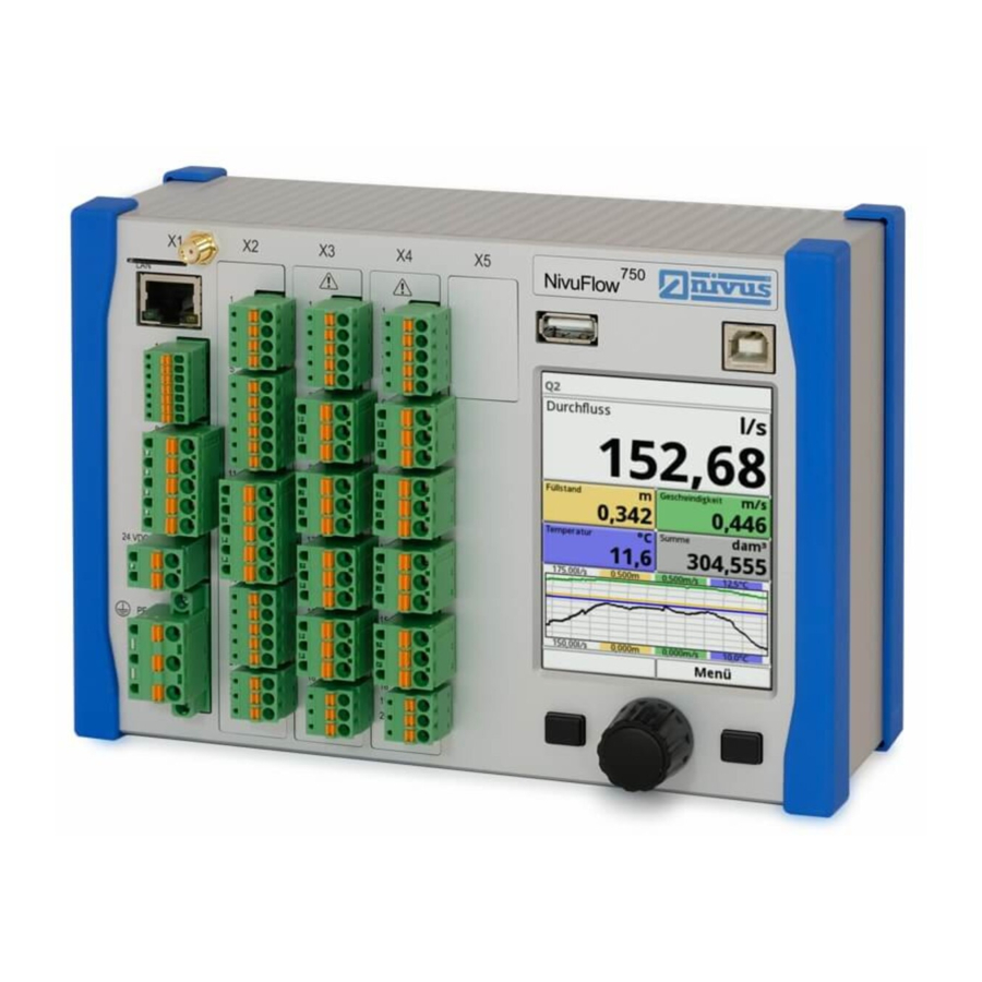
9. Plugin X5 - spare plugin port (unused) 10. USB-A interface (data transfer) 11. USB-B interface (service) 12. Graphic display 13. Function key 14. Rotary pushbutton 15. Function key 16. DIN rail fastening Fig. 3-1 eneral view NivuFlow 750 page 14... -
Page 15: Connectable Sensors
Product specification Connectable sensors The image below provides an overview on the connectable sensors. 1. Flow velocity wedge sensor, Type POA-V2H1/V2U1 2. Flow velocity wedge sensor, Type POA-V200/V2D0 3. Flow velocity wedge sensor, Type CS2 4. Pipe sensor, Type CS2, with sensor screw joint and retaining element 5. -
Page 16: Use In Accordance With The Requirements
The manufacturer cannot be held responsible for any damage resulting from improper use. The user alone bears any risk. The permanent flow meter Type NivuFlow 750 including the accompanying sensors is designed for continuous flow measurement of slight to heavily polluted media in part filled and full chan- nels, pipes and similar. -
Page 17: Device Identification
Product specification Device identification The instructions contained within this manual are valid only for the type of device specified on the title page. The name plate is fixed on the side of the enclosure and contains the following: • Name and address of the manufacturer •... -
Page 18: Specifications
Inputs - 1 x 4-20 mA for external level (2-wire probe) - 1 x RxTx-Bus for NIVUS air-ultrasonic sensor Type OCL - 1 x (Type S1) or 7 x (Type M3) 0/4-20 mA with 12 Bit reso- lution for external level, external controller setpoint and data storage of external units, accuracy ±0.4 % of measuring... -
Page 19: Configuration
Product specification Sensors Observe the specifications of the according sensors as described in the respective instruction manuals or technical descriptions. Storing The following storing conditions shall be strictly adhered to: • max. temperature: +80 °C • min. temperature: - 30 °C •... -
Page 20: Delivery
NIVUS cannot be held responsible for any damage resulting due to the use of non-original parts and non-original accessories. You can find original manufacturer spare parts or accessories in chapter 9.5. -
Page 21: Functional Principle
The NivuFlow 750 can be used for measurements in part filled flumes as well as in full pipes. The device types SR, M3 and M9 are equipped with an extra 3-step controller to control a slide valve or other control elements. -
Page 22: Level Measurement Using Pressure
Instruction manual NivuFlow 750 • = filling level = sound running time = time between transmitted and received signal At a medium temperature of 20 °C the sound running time in water is 1480 m/s. The temperature-dependent deviation is 0.23 % per Kelvin. -
Page 23: Flow Velocity Detection
Functional Principle i-10 i-15 4 mA (empty) 0 % pan distance to sensor 10,0 15,0 face in m 20 mA (full) 100 % pan distance to sensor 0,125 0,300 0,300 0,500 face in m Measurement span (value at 20 mA) 2,875 14,5 Fig. - Page 24 Instruction manual NivuFlow 750 Fig. 4-3 Situation at second signal detection The DSP checks both received reflection patterns for similarities using the cross correlation method. All existing signal differences (caused by new or rotated particles) are rejected so that two similar but temporarily offset signal patterns are left for velocity evaluation.
- Page 25 Functional Principle The result is based on the geometric data of the flume and the velocity distribution. In asymmetric flow profiles and heavily structured profiles it is recommended to use more than one flow velocity sensor. The entered sensor positions and the according individual vertical V-profiles are included with the overall 3D-profile and are indicated as well.
-
Page 26: Installation And Connection
The NivuFlow with DIN rail fastening is conceived for installation in switching cabinets. It can be also installed in field enclosures or similar. Due to the protection degree, NivuFlow 750 is not suitable to be installed directly on site without protective measures. -
Page 27: Electric Installation
Installation and Connection Choose the installation place for your instrument considering specific criteria. Strictly avoid: • direct sunlight • objects radiating strong heat • permissible ambient temperature: -20° C to +40° C • objects with strong electromagnetic fields (frequency converters, high voltage power lines or similar) •... -
Page 28: Connection Clamp For Protective Earth Conductor And Ac Power Supply
5.2.2 Power supply DC The DC version of NivuFlow 750 can be directly operated from the 24 V direct current network of a control cabinet. The input voltage available at the input clamps must not fall below 10.0 V at maximum load (20 W). The clamp voltage at no-load operation is not allowed to rise above a maximum of 35.0 V. -
Page 29: Sensors
Using protection on both sides will reduce the max. cable length to 120 m (see chapter 5.4). Between iXT/MPX and transmitter: If a NIVUS cable type LiYC11Y 2 x 1,5mm² + 1 x 2 x 0,34 mm² + PA is used, the maximum dis- tance between iXT and the transmitter is 50 m. -
Page 30: Sensor Connection
(+PA 1.5 / 2.5) RxTx - max. 150 m white RxTx + 1. Connectable flow velocity sensors Fig. 5-9 Connecting flow velocity sensors to NivuFlow 750, Type S1/SR This flow velocity sensors can be connected to the Nivuflow: • POA-V200 • POA-V2H1 •... - Page 31 Installation and Connection 1. Sensor 1 (leading sensor) - or Electronic box 2. Sensor 2/3 (additional sensors for flow velocity) - or Electronic box Fig. 5-10 Connecting 2/3 flow velocity sensors to type M3 page 31...
- Page 32 Instruction manual NivuFlow 750 Fig. 5-11 Connecting Mini sensor family to type S1/SR Connecting a CSM-D sensor is exactly the same as the CSM / DSM. To connect 2 or 3 Electronic boxes, proceed as described the connection of flow velocity sensors in Fig.
- Page 33 Installation and Connection Flow velocity sensor with integrated pressure measurement cell Observe the following connection notes when connecting a flow velocity sensor with integrated pressure measurement cell to NivuFlow 750, type M3: • use only one sensor with integrated pressure measurement cell •...
- Page 34 Instruction manual NivuFlow 750 Fig. 5-12 Connection air ultrasonic sensor, type OCL page 34...
- Page 35 The level measurement can also be carried out by a 2-wire sensor (NivuBar, NivuCompact 2-wire echo sounder or similar) which is supplied by the NivuFlow. Connect the 2-wire sensor to the following terminals: NivuFlow 750 HART Zone 1 Fig. 5-13 Connecting a 2-wire sensor EX for level measurement If the mA signal of the level measurement is provided from an external transmitter (e.g.
-
Page 36: Overvoltage Protection
For effective protection of the NivuFlow transmitter it is necessary to protect power supply as well as mA-output using overvoltage protection devices. NIVUS recommends surge arrestors types EnerPro 220Tr, EnerPro 24Tr (for 24 V DC) for the mains supply, as well type DataPro 2x1 24/24Tr for mA-inputs and mA-outputs. - Page 37 EnerPro 2 x 1 - 24 V mind. mm² Fig. 5-16 Overvoltage protection for power supply DC Do not reverse protected (p) NivuFlow 750 S1/SR and unprotected sides of overvoltage protection. Outer shield Supply + DataPro UE-GND 2 x 1 12 V / 12 V 11µTr (N)
- Page 38 Instruction manual NivuFlow 750 Do not reverse protected (p) NivuFlow 750 M3 and unprotected sides of overvoltage protection. Outer shield Supply + DataPro UE-GND 2 x 1 12 V / 12 V 11µTr (N) blue RxTx - OCL-L1 RxTx + min.
- Page 39 Installation and Connection Do not reverse protected (p) NivuFlow 750 M3 and unprotected sides of overvoltage protection. Outer shield Supply + DataPro UE-GND 2 x 1 12 V / 12 V 11µTr (N) blue RxTx - RxTx + mind. mm²...
- Page 40 Instruction manual NivuFlow 750 Do not reverse protected (p) and unprotected sides of overvoltage protection. NivuFlow 750 DataPro 2 x 1 HART 24 V / 24 V Zone 1 min. mm² i-Sensor NivuBar NivuCompact Fig. 5-20 Overvoltage protection external level measurement...
- Page 41 Analog DataPro output 4 2 x 1 24 V / 24 V min. mm² Fig. 5-22 Overvoltage protection analog outputs NivuFlow 750, type M3 SonicPro SonicPro 3 x 1 24/24 3 x 1 24/24 RxTx + NivuFlow RxTx - min.
-
Page 42: Connection To The Terminal Blocks
Instruction manual NivuFlow 750 Connection to the Terminal Blocks All NivuFlow transmitters are equipped with plug-in spring-cage terminal blocks. The use of these plug-in spring-cage terminal blocks enables an easy pre-installation of the transmitter. This allows a possible revision of individual sensors, input signals and output signals etc. Also a fast transmitter exchange is possible. -
Page 43: Transmitter Connection
Transmitter Connection 5.6.1 Types of Measurement Transmitter The NivuFlow 750 measurement transmitter is available in 3 different versions: • Type S1 - Standard version each for one flow velocity sensor, one level sensor and the option to additionally connect an external level sensor •... - Page 44 + RxTx + +24 VDC RxTx - 0 VDC RxTx + AI1 (HART) GND AI1+2 +AI3 +AO1 +AI4 +AO2 +AI5 GND AO1+2 GND AI3-5 +AO3 +AO4 GND AO3+4 Fig. 5-25 General connection diagram - NivuFlow 750, type SR page 44...
- Page 45 Installation and Connection Fig. 5-26 General connection diagram - NivuFlow 750, type M3 page 45...
-
Page 46: Switching On Voltage Supply
NivuFlow 750 5.6.3 Switching on voltage supply Depending on the type of NivuFlow 750 used the unit can be powered with 100-240 V AC (-15/+10 %) or with 9-35 V DC. 1. 24 V DC connection of type NivuFlow 750 2. - Page 47 Installation and Connection 800 mA 9-35 V DC Fig. 5-29 DC connections of power supply page 47...
-
Page 48: Putting Into Operation
NivuFlow into operation. Read this instruction manual carefully in order to guarantee proper function of the NivuFlow 750 zu gewährleisten. Verdrahten Sie das NivuFlow nach dem vorgegebenen Anschlussbild in Kapi- tel 5.6.2. -
Page 49: Nivuflow Control Elements
Putting into Operation NivuFlow Control Elements Two control buttons and one rotary pushbutton are available for the setting of parameters and to input required data. 1. Left function key (Back button) 2. Right function key (variable: Menu/Data entry) 3. Rotary pushbutton Fig. -
Page 50: Menus
Instruction Manual NivuFlow 750 Menus There are six basic menus available which can be viewed and selected by pressing the right function key. Fig. 6-3 Main menu The menus are: Application This is the most comprehensive menu of the NivuFlow. It guides the... -
Page 51: Operation Basics
Putting into Operation Operation Basics The NivuFlow is operated completely in dialog mode supported by the graphs on the display. To select individual menus and sub-menus use the rotary pushbutton as well as the both function keys. Left function key Is required to exit menus or submenus. -
Page 52: Parameter Setting
General Overview Main Menu All settings of the NivuFlow 750 are grouped in total six setup menus. The individual menus are described in this chapter. The options can be found in the main menu as described in the figure below. - Page 53 Parameter setting Within this system, additional functions are: • 2-point step control programming • Diagnostics of sensors Inputs and outputs or of the complete system Constant, fixed sludge levels can be entered and the low flow suppression can be set here. Damping and signal evaluation and signal output stability can be modified here as well.
-
Page 54: Application
Instruction manual NivuFlow 750 Display You can adjust the backlight level of the display. Possible corrections of the five output fields of the main menu. Connections Set here whether an iXT intelligent Ex-Separation Module or a sensor multiplexer are connected to the transmitter. - Page 55 Parameter setting The name of the measurement place is entered by the rotary pushbutton. Press the rotary pushbutton - a virtual keypad featuring individually selectable letters is indicated in the lower half of the display. Turn the rotary pushbutton to navigate through the virtual keypad. Characters highlighted blue feature dual functions.
-
Page 56: Channel Profile
The name of measurement is taken to the main menu and is displayed there. 7.3.1.2 Channel Profile The NivuFlow 750 allows to select from a wide variety of standardised channel profiles mainly used in practice. Since particularly older channel systems often have special shapes, the NivuFlow 750 moreover provides the option to enter dimensions or heights/areas of symmetric and asymmetric channels in tables. - Page 57 Parameter setting Basic selection of channel profiles: Turn the rotary pushbutton until the “channel profile” is highlighted blue. Press the rotary pushbutton. This opens a drop-down menu. Turn the rotary pushbutton and select one of the defined profiles. Confirm the selected profile by pressing the rotary pushbutton again. The selected profile will be displayed.
- Page 58 1:1.5. Squeezed or shrunk ovoid profiles need to be set using a free profile. When setting the ovoid profile parameters only the maximum channel width needs to be entered. The NivuFlow 750 calculates the height automatically by using the fixed 1:1.5 ratio. page 58...
- Page 59 Parameter setting Fig. 7-12 Ovoid profile 1:1,5 settings Rectangle This selection can be used to set the parameters of channels featuring vertical walls and a horizontal bottom. The parameters can be easily set by merely entering width and height of the channel.
- Page 60 Instruction manual NivuFlow 750 Fig. 7-14 3D graph with dry weather flume U-profile The U-profile is composed from a bottom semicircle and vertical walls. The semicircle radius here is ½ the channel width and is entered automatically by the system. Profiles with radii larger than 0.5 x channel width should be created as free profiles.
- Page 61 Parameter setting Fig. 7-16 Programming trapezoid profile with rectangular top Fig. 7-17 Programming trapezoid profile without rectangular top Right as with rectangular profiles, a dry weather flume can be added as extra option. Fig. 7-18 Trapezoid profile with dry weather flume page 61...
- Page 62 Enter height and width of all other breakpoints “freely”. The distance between individual height breakpoints may vary. Not all of the 32 breakpoints need to be necessarily entered in order to define the profile since the NivuFlow 750 linearises between individual breakpoints.
- Page 63 The distance between individual height breakpoints may vary. Not all of the 32 breakpoints need to be necessarily entered in order to define the profile since the NivuFlow 750 linearises between individual breakpoints. In case of large irregular changes of the channel dimensions select a lower distance between breakpoints in this section.
- Page 64 Instruction manual NivuFlow 750 Fig. 7-21 Setting parameters using free asymmetric height-width-width profile Free symmetric height-area profile Some hydraulic tables may contain height-area value pairs instead of height-width to specify symmetric channels. In such cases enter the value pairs into the selected height-area table. The following procedure is the same as with programming height-width profiles.
-
Page 65: Low-Flow Suppression
Parameter setting Fig. 7-23 Programming Q/h-characteristics 7.3.1.3 Low-flow suppression Low-flow rate This parameter is to suppress lowest movement or apparent flow rates. The main area of use is the measurement of overflow volumes in buildings with permanent dam-up. Rotate the rotary pushbutton until >Low-flow suppression< Is highlighted. A drop- down menu will open. -
Page 66: Sludge Level
By setting a stability time invalid level and velocity values are disregarded (>0< is a valid entry!!). During this period the NivuFlow 750 operates using the latest valid reading. The invalid value will not be accepted as such and the according calculations and actions will not be carried out before the stability time has expired. -
Page 67: H-Sensors
Press the rotary pushbutton - the PLUS toggles to MINUS and the selection lists open up. Choose the sensor type connected to the NivuFlow 750. Rotate the rotary pushbutton until you reach the desired sensor type and tick the checkbox by pressing the rotary pushbutton. - Page 68 The use of 0/4-20 mA signal from external transmitters such as NivuMaster or MultiRanger can be enabled in this menu as well. i-Sensor Here the ultrasonic i-Series sensor by NIVUS can be connected using the HART interface. NIVUS air-ultrasound The level is measured from the top down using an air-ultrasonic sensor Type OCL-L1 or DSM-L0.
-
Page 69: Define Measuring Ranges
Parameter setting Integ. water-ultra- The level is measured from the bottom up with Type POA-V2H, sound POA-V2U, CS2-V2H or CS2-V2U combi sensor using water ultrasound. This sensor type is appropriate for discharge detection in medium part filled areas. The combi sensor shall be installed exactly in the center of the bottom (deviation ±2 °). - Page 70 Indication of programmable ranges You can assign one level sensor to each programming section (see Fig. 7-27 -„Level sensor selection“). The NivuFlow 750 will automatically assign the sensors to the appropriate program- ming sections. The assignment depends on the channel shape set.
- Page 71 Parameter setting Fig. 7-30 Level sensor assignment to programming section The range of each programming section can be modified. To do so, change the respective >Switchover height< accordingly Important Note Observe to accurately specify the positioning values of the individual sensors. Sensors with built-in pressure measurement cell shall be installed at the lowest point of the chan- nel bottom (sensor Type POA-V2D, POA-V2U, CS2-V2H, CS2-V2U and CSM-V1D).
- Page 72 Important Note When using i-Sensors (connection via HART interface) necessarily observe to correctly specify the sensor type. The NivuFlow 750 automatically takes over the sensor-specific data. In i-Sensor selection menu, tick the iXT/MPX checkbox as soon as the sensor is connected via the HART interface of an iXT or MPX.
-
Page 73: V-Sensors
NivuFlow 750 type SR - 1 flow velocity sensor • NivuFlow 750 type M3 - up to 3 flow velocity sensors Open the v-Sensor menu. With a Type M3 transmitter connected a selection box showing options 1-3 is indicated in the top right-hand corner. This box can be used to set the parameters of all connected sensors following each other. -
Page 74: Sensor Types
Instruction manual NivuFlow 750 Press the right-hand function key (Tab) to move to v-Sensor 2. Tick the “Active“ checkbox. Now the parameters for the activated sensor can be set. The active sensor is directly visible in the application graph. The sensor of which the parameters are currently being set is highlighted in the graph. The other available sensors at the same time appear as simple outlines. -
Page 75: Sensor Mounting Position
Parameter setting 7.3.3.3 Sensor mounting position Extra application parameters can be set for the installation of v-sensors. These parameters are intended mainly for installation positions which vary from the default settings. Rotate the rotary pushbutton until >Mounting< is highlighted blue. Press the rotary pushbutton - the PLUS toggles to MINUS and an input menu opens up. - Page 76 Instruction manual NivuFlow 750 Fig. 7-39 Parameter setting only by entering the angle Fig. 7-40 Flush-mounted display at the right angle This function is not available with other channels profiles. Input box >Mounting height< To set the mounting height parameters proceed as follows: Measure the distance between the bottom edge of the mounting plate (v-sensor) and the lowest point of the channel bottom.
- Page 77 Parameter setting Fig. 7-41 Parameter setting mounting height In structured channel profiles such as channels featuring a dry weather flume and a berm, the lowest point within the channel is equal to the zero point. The lowest point in this case is the bottom of the dry weather flume.
- Page 78 2 left v-Sensor 3 right The NivuFlow 750 calculation procedures are based on the v-sensor installed in the channel center. If the v-sensor needs to be installed out of the center the offset must be entered in >Dis- tance center<.
- Page 79 U-profile In such a case the altered angles of incidence need to be entered in the NivuFlow 750. The vertical, upward beam of the ultrasonic signal is the reference point.
-
Page 80: V-Determination Low Levels
The default setting is 100 %. Note The weighting value depends on the application as well as the sensor position. Such applications demand comprehensive knowledge on fluid mechanics and require NIVUS personnel or an authorised expert company. Fig. 7-46 Weighting v-sensor 7.3.3.4 v-Determination low levels Due to constructional and physical reasons the flow velocity sensors cannot measure the flow velocity anymore below a certain minimum level. - Page 81 As soon as the level falls significantly, from a certain point on it is not possible anymore to meas- ure the flow velocity. The NivuFlow 750 creates an internal table of v/h-readings at the point of the minimum level (h-crit) on which a flow velocity still can be measured. The system here uses the latest measurable flow velocity reading.
-
Page 82: Limitation Of Velocity Evaluation
(chapter 7.3.3.3, Fig. 7-41). The lowest possible level required to measure flow velocities is automatically determined by the NivuFlow 750. If this option is disabled the system utilises the value set in >h-manual< as h-crit. Per default >h-manual< Is set to >0<. -
Page 83: Inputs/Outputs (Analog)
Parameter setting Note EIt is not possible to increase the possible flow velocity evaluation to values higher than the technical limits as described in chapter 3.5. The system will not accept such entries. Fig. 7-49 Limitation of velocity evaluation 7.3.4 Inputs/Outputs (analog) This menu is to define the function of the analog as well as digital inputs and outputs. -
Page 84: Analog Inputs
Fig. 7-52 Activation analog inputs Currently the analog inputs can be used as external readings only. Therefore, the NivuFlow 750 can be used as an extra data logger for readings from external systems. This however does not influence the unit’s capabilities as flow meter. - Page 85 Parameter setting Fig. 7-53 Parameter setting analog input After activating the analog inputs the input range can be either set to 0-20 mA or 4-20 mA. Fig. 7-54 Selection input range The units are indicated in a text box. You may also specify individual units. The number of char- acters describing the unit must not exceed a maximum of 5 characters.
-
Page 86: Analog Outputs
Instruction manual NivuFlow 750 Finally set the scale to save. Fig. 7-56 Scale 7.3.4.2 Analog outputs The number of analog outputs is depending on the device type: • Typ S1 = 2 analog outputs • Typ SR = 2 analog outputs •... - Page 87 Parameter setting Fig. 7-58 Activation analog output Following functions of the analog output are possible: • Flow Output of the application flow rate (calculated from average flow velocity and wetted cross-section) at the selected analog output. • Level The level used for calculation is available at the selected analog output. This is the level enabled for the current level section in menu Application/h-Sensors.
- Page 88 Instruction manual NivuFlow 750 Sensor velocity • In the event of using multiple flow velocity sensors and if the average flow velocity of the individual measurement paths is to be determined, the desired flow velocity sensor can be selected here in order to output its readings at the analog output.
-
Page 89: Digital Inputs
Parameter setting Fig. 7-61 Programming output range It is possible to define a certain behaviour for the analog output to react in case if missing read- ings. Select from the settings below: • 0 mA • 3,5 mA • 21 mA •... - Page 90 Instruction manual NivuFlow 750 Fig. 7-63 Select digital inputs Fig. 7-64 Activation of digital inputs The following functions can be assigned to the digital inputs: • Block v-measurement By using an external contact (float switch, pressure bell switch..) the flow measurement can be blocked as long as a signal is available at the am digital input.
-
Page 91: Digital Outputs
Parameter setting Impulse counter • The system detects and saves the number of the ongoing signals at the digital input. The counter simply counts the status changes detected at the digital input (1->0 or 0->1). If this function is selected determine if the rising edge (status change >0< to >1<) or the falling edge (status change >1<... - Page 92 Instruction manual NivuFlow 750 Fig. 7-66 Select digital outputs Fig. 7-67 Activation of digital outputs The following functions can be assigned to the digital outputs: Sum impulses • Output of volume-proportional sum impulses. The parameters below can be set here:...
- Page 93 Parameter setting Fig. 7-68 Programming pulse generator • Limit contact flow In >Threshold off< and >Threshold on< set one flow limit value for each point. A digital signal will be output if this flow limit value is exceeded. If the flow should fall below the second flow limit value the digital signal will be reset = hysteresis function to avoid output flutter.
- Page 94 Instruction manual NivuFlow 750 Limit contact velocity • The digital signal in the event of exceeding an adjustable velocity limit value will be issued here. Proceed as described in >Limit contact flow<. The calculated average flow velocity (calculated even by using 2 or 3 sensors) is used here.
-
Page 95: Q-Control
Parameter setting Fig. 7-70 Error messages • Modbus Slave The digital output can be used via Modbus to output controlled signals from other systems. Fig. 7-71 Adjustment options Logic 7.3.5 Q-Control This function is currently not supported. Fig. 7-72 Q-Control page 95... -
Page 96: Diagnostics
Instruction manual NivuFlow 750 7.3.6 Diagnostics The diagnostics menu is a menu used for indication and simulations. The settings below can be verified or checked here: • Sensor functions • Sensor serial numbers • Sensor software versions • Inputs and outputs •... - Page 97 Parameter setting One green bar is shown if only one application range is used for the entire application range, the combination green/red indicates the use of 2 ranges. In each section always the corrected and used reading as well as the raw value of the measure- ment is shown.
- Page 98 Instruction manual NivuFlow 750 Fig. 7-76 Select pressure sensor Fig. 7-77 Screen sensor information pressure sensor In case of using a water-ultrasonic sensor it is possible to additionally read the current echo image as well as the noise level of the sensor cable connection. The latter provides information on the quality of the sensor cable connection (interference).
- Page 99 Parameter setting Fig. 7-79 Sensor information and echo image of water-ultrasonic sensor Fig. 7-80 Select air-ultrasonic sensor Fig. 7-81 Sensor information and echo image of air-ultrasonic sensor page 99...
-
Page 100: V-Sensors
Instruction manual NivuFlow 750 7.3.6.2 v-Sensors Fig. 7-82 Select v-sensor The v-Sensors diagnostic menu apart from hardware information indicates the measured flow velocity profile as well. Use the right-hand function key (Tab) to toggle between the individual sensors. 1. Currently selected sensor 2. - Page 101 Press the rotary pushbutton - the current information is shown as table. Fig. 7-85 Select gate display Fig. 7-86 Table of measured single velocities The information on the measurement and trigger quality as well as the signal cable noise level are relevant to the NIVUS commissioning and service personnel. page 101...
- Page 102 Instruction manual NivuFlow 750 Fig. 7-87 Select 3D Flow profile The graphic flow profile is calculated following hydraulic methods. The factors below are taken into account while calculating the flow profile: • Individual velocities • Individual levels • Channel profile •...
-
Page 103: Analog Inputs
Parameter setting Fig. 7-89 Various profile views 7.3.6.3 Analog inputs Fig. 7-90 Analog inputs selections This menu can be used to indicate the current values on the NF7 inputs as well as the readings assigned to this value by using the measurement span. The number of analog inputs depends on the instrument type: •... -
Page 104: Analog Outputs
Instruction manual NivuFlow 750 Fig. 7-91 Displayed signal values of type M3 7.3.6.4 Analog outputs Fig. 7-92 Analog output selection This menu can be used to indicate the calculated current values to be output through the analog converter as well as the readings assigned to this values by using the measurement span. More- over it is possible to simulate the analog values. - Page 105 It is absolutely necessary to have a safety person available! Disregarding may lead to personal injury or damage your facility. NIVUS herewith in advance refuse any responsibility for any possible damage to persons or objects at any extent due to the extremely high risk of danger and unforeseeable conse-...
- Page 106 NivuFlow 750 DANGER Effects on plant sections The simulation of NivuFlow 750 outputs will directly affect any following plant sections without any safety locking measures! Simulations are allowed to be executed exclusively by qualified expert personnel. Observe the hints contained within the above warning!
-
Page 107: Digital Inputs
Parameter setting Fig. 7-97 Setting the desired current value for simulation Observe that the analog output(s) will provide the current values entered as long as the simulation menu is active. Press the left-hand function key to exit the simulation menu. 7.3.6.5 Digital inputs Fig. -
Page 108: Digital Outputs
Instruction manual NivuFlow 750 Fig. 7-99 Digital inputs 7.3.6.6 Digital outputs Fig. 7-100 Select Digital outputs The digital output values set can be viewed using this menu. A simulation of digital outputs is available from this menu too. The number of digital outputs depends on the instrument type: •... - Page 109 It is absolutely necessary to have a safety person available! Disregarding may lead to personal injury or damage your facility. NIVUS herewith in advance refuse any responsibility for any possible damage to persons or objects at any extent due to the extremely high risk of danger and unforeseeable conse-...
- Page 110 DANGER DANGER Effects on plant sections The simulation of NivuFlow 750 outputs will directly affect any following plant sections without any safety locking measures! Simulations are allowed to be executed exclusively by qualified expert personnel. Observe the hints contained within the above warning!
-
Page 111: Q-Control
Parameter setting Observe that the digital output(s) will provide the current values entered as long as the simulation menu is active.. Press the left-hand function key to exit the simulation menu. 7.3.6.7 Q-Control This menu is not supported at present. Fig. -
Page 112: Simulation
This menu allows to simulate theoretical flow. Simulation is carried out by entering assumed values for level and velocity. These values do not really exist. Using the dimensions of the programmed channel as basis, the NivuFlow 750 calculates the flow rate prevailing by using the simulated values. - Page 113 DANGER Effects on plant sections The simulation of NivuFlow 750 outputs will directly affect any following plant sections without any safety locking measures! Simulations are allowed to be executed exclusively by qualified expert personnel.
- Page 114 Instruction manual NivuFlow 750 It is essential to follow the safety instructions mentioned before entering the password! Enter your password. Rotate the rotary pushbutton until the desired value to simulate (level or velocity) is highlighted blue. Select the desired measurement value.
-
Page 115: Parameter Menu Data
Parameter setting Parameter Menu Data Fig. 7-111 Menu Data 7.4.1 Trend The trend graph is a representational recorder function. Selecting the trend graph provides access to the data previously saved (history). Fig. 7-112 Select Trend graph Select the desired data time range. The selected data time range is shown. - Page 116 Instruction manual NivuFlow 750 1. Selection of time and date 2. Indication period 3. Scaling max. range 4. Display with grid lines 5. Date time line 6. Scaling 0-point 7. Browse previous / next Fig. 7-113 Trend graph details In the top area of the screen the date/time selection (see Fig. 7-113) can be found. The line is highlighted blue and therefore active.
- Page 117 Parameter setting Press the left-hand function key (Back) if you wish to cancel your entry. Fig. 7-115 Changing the day The selected period is shown between the left-hand and the right-hand edge of the screen. Fig. 7-116 Indication of newly selected time range The range within data is to be shown can be modified (see Fig.
- Page 118 Instruction manual NivuFlow 750 The display grid is non-adjustable. If “Hour“ is selected as period, the indication starts on the left-hand side at minute “0“ and ends on the right-hand side at minute “59“. To improve readability the screen is subdivided by three vertical grid lines. Each of the resulting segments represents a period of 15 minutes.
- Page 119 Parameter setting Fig. 7-117 Selecting the indication period Fig. 7-118 Browse function „Back“ Fig. 7-119 Display period „browsed back“ Note Selecting the period of 4 weeks may take a few seconds to completely load the required data. page 119...
-
Page 120: Day Totals
It is possible to view older day values as well. The prerequisite to show older values is that the instrument has been operated for a longer period. Example: 98 values - The unit has been in operation for 98 days Otherwise only day values are readable, when the NivuFlow 750 has been working. page 120... - Page 121 The flow rate totals of this period are missing during the shut-down time. As soon as the NivuFlow 750 is shut down before the next summing time and remains to be off until the next summing time, no totals will be created for this 24-hours period (see Fig. 7-123).
-
Page 122: Usb Stick
Fig. 7-124 Select sub menu USB stick The NivuFlow 750 has an internal data memory. It is possible to transfer either portions of your data or all saved readings to an USB stick. This section allows you to determine the desired transmission period. - Page 123 Parameter setting Per default the NivuFlow 750 is set as to transfer the data containing the period between the latest previous data transmission and the current time. To save data to USB stick proceed as follows: Press the rotary pushbutton to activate the first box Rotate the rotary pushbutton to set the desired day as starting time.
- Page 124 • Average flow velocities of v-sensor(s) 1, 2 and 3 (if used) • Parameter values for the NIVUS-specific velocity evaluation method >COSP< • Trigger and hydraulic qualities of v-sensor(s) 1, 2 and 3 (if used). page 124...
- Page 125 Parameter setting Expert This option should be used only by trained service personnel or the manufacturer’s developers. Such data sets may become very large very quickly. Apart from the data contained with the “Extended” data set, this option includes extra information on all individual gate velocities as well as all gate positions of any connected v-sensors.
- Page 126 Instruction manual NivuFlow 750 Fig. 7-128 Command for measurement data saving Use the “Load parameters“ command to load parameter sets previously saved back from USB stick to the transmitter. Fig. 7-129 Load saved parameter file The “Save parameters“ function is to save measurement place parameters to USB stick. This option creates and saves 3 files.
- Page 127 Parameter setting File name remarks: • XXXX = Name of the measurement place set • = Year • = Month • = Day • = Hour • = Minute Fig. 7-130 Save parameters Unformatted or incorrectly formatted USB can be formatted correctly directly on the instrument: Rotate the rotary pushbutton until >Format USB stick<...
-
Page 128: Data Storage (Internal)
Instruction manual NivuFlow 750 7.4.4 Data storage (internal) This submenu allows to modify the storage cycle and to delete the internal memory. Fig. 7-132 Select data storage The storage cycle options are: • 30 seconds • 1 minute • 2 minutes •... -
Page 129: System
Parameter setting Important Note Deleted data cannot be restored again! Fig. 7-134 Delete internal storage System 7.5.1 Information Fig. 7-135 Select sub menu system This menu is for viewing only and provides the device information below: • Serial No. And Article No. •... -
Page 130: Region Settings
Instruction manual NivuFlow 750 Fig. 7-136 System information display 7.5.2 Region Settings In this menu you can do the following settings: • Operating language • Date format • Units for measurement values. Here, a distinction between displayed and stored measurement values is possible. - Page 131 Rotate the rotary pushbutton to the first option in the list. Here you can define the type of decimal separator (comma or dot) The decimal separators determined here are used only for indication on the NivuFlow 750 dis- play. page 131...
- Page 132 Instruction manual NivuFlow 750 Fig. 7-140 Select Decimal separations Next, determine the unit system. Select from: • Metric • English • American Depending on the unit system selected the units below can be chosen: • In the metric system (e.g. Litre, cubic meter, cm/s etc.) •...
- Page 133 Parameter setting Fig. 7-142 Display units in metric system Fig. 7-143 Unit system settings English Fig. 7-144 Unit system settings in English system When setting the >Units memory< proceed exactly as described in >Units<. In >Units memory< the readings are converted and saved according to the selected unit. Choose between >Comma<...
- Page 134 Instruction manual NivuFlow 750 Fig. 7-145 Change decimal separators Depending on the intended use select from the units below for storage: • In metric system e.g. l/s, m³/s, m³/d, cm/s etc. • In English system e.g. ft³/s, in, gal/min, Mgal/d, in/s, yd/s etc.
-
Page 135: Time/Date
Parameter setting 7.5.3 Time/Date Use this sub-menu to modify the current date and the transmitter system time. This function is required to change between summer time and winter time or if the internal buffer battery is exhausted and after mains power failure. If the transmitter is operated for a long time internal clock deviations must be expected. - Page 136 Instruction manual NivuFlow 750 Fig. 7-149 Select submenu error messages Fig. 7-150 Current error messages displayed Before you can delete the error storage, you need to enter the password. This prevents unauthor- ized or unintentional deletion. Fig. 7-151 Delete current error messages...
-
Page 137: Service
Service level selected Change password The default password is >2718<. NIVUS recommends to change the password to save the sys- tem against unauthorized access. You can use any values or characters for the password. The password length is limited to 10 characters. - Page 138 Write down the password and keep it in a safe place. Once you have modified the password, your old password CANNOT be restored by NIVUS! Should the password get lost a general reset of the complete system needs to be executed.
-
Page 139: Communication
This is why no further details will be described in this respect here. If you should not have basic knowledge on network integration, such tasks should be left to IT experts or NIVUS commissioning personnel. Fig. 7-157 Select sub menu communication The TCP/IP menu allows to set options for data transport in a decentralised network. - Page 140 NivuFlow 750 Fig. 7-158 TCP/IP settings The internal WEB browser is currently not supported. Fig. 7-159 WEB-Server In preparation In future the NivuFlow 750 can be used as a HART slave subordinated systems. Fig. 7-160 HART interface programming page 140...
- Page 141 Parameter setting You can integrate the NivuFlow 750 in other systems by Modbus TCP. If required, the Modbus protocol is available upon request. Please contact the NIVUS GmbH head office in Eppingen. Fig. 7-161 Modbus programming selection Here the following features are available: •...
- Page 142 Instruction manual NivuFlow 750 Fig. 7-163 Baud rate settings Fig. 7-164 Slave address definition Fig. 7-165 Programming scale values page 142...
-
Page 143: Display
The display will be dimmed automatically if not in use over a certain period. The delay time can be determined in advance. As soon as settings are made on the NivuFlow 750 (e.g. if a key is pressed) the display instantly switches over to standard brightness. - Page 144 Instruction manual NivuFlow 750 Fig. 7-168 Delay time until backlight dimming The 5 main display output fields (Flow, Level, Velocity, Temperature and Sum) can be defined freely regarding name as well as decimal digits. The output field colours correspond to the value colours in the main display.
-
Page 145: Connections
Parameter setting Fig. 7-170 Entering the output field label The number of decimal digits can be modified the same way as described before. A maximum of 5 decimal digits can be specified. Note Observe if the number of decimal digits makes sense regarding the sensors. Furthermore observe the number of decimal digits in relation to the used measurement units. - Page 146 Instruction manual NivuFlow 750 Fig. 7-172 Select sub menu connections Mark the checkbox, if you use an iXT or MPX. Otherwise sensor and module will not be detected. Fig. 7-173 Activation when using an iXT or MPX page 146...
-
Page 147: Main Display
Main Display Main Display When in operation mode, the NivuFlow 750 indicates the following important readings: • Flow quantity • Current fill level (for calculation) • Velocity (calculated average flow velocity) • Medium temperature • The following information can be found in the top display line: •... -
Page 148: Flow Screen
Instruction Manual NivuFlow 750 The menu allows to directly access the most relevant settings and information. Rotate the rotary pushbutton until the desired section is highlighted in black. Press the rotary pushbutton - the according section will open a dialog window. - Page 149 Main Display Fig. 8-4 Measurement place settings By directly accessing the diagnostic menu you can instantly carry out verifications within the limits of the application programmed: • Connected level and flow velocity sensors • Physical condition of analog and digital inputs •...
- Page 150 Instruction Manual NivuFlow 750 Fig. 8-6 Adjust dimming Fig. 8-7 Change text for measurement value Fig. 8-8 Change digits After having modified the system-specific parameters, you need to confirm that the modifications are saved. A table indicating the wording of the current error message will come up as soon as the >Error mes- sages<...
-
Page 151: Display Level
The dialog shows: • Firmware version • Article number • Serial number The current echo profiles of used NIVUS ultrasonic sensors can be assessed here. Fig. 8-10 Level sensor settings and their operation ranges page 151... - Page 152 Instruction Manual NivuFlow 750 Fig. 8-11 Direct selection of individual sensor diagnostics Fig. 8-12 Pressure sensor screen Fig. 8-13 Screen Water-US page 152...
-
Page 153: Display Flow Velocity
Main Display Fig. 8-14 Screen Echo Air-US You can get directly from here to the general display menu by using the display selection. The section has been previously described in Chapter 8.1. Fig. 8-15 Display menu Display flow velocity This dialog allows to directly access the settings of the programmed flow velocity sensors. The following parameters can be edited here: •... - Page 154 Instruction Manual NivuFlow 750 Fig. 8-16 Settings and positions of flow velocity sensors The dialog shows: • Article no. and serial no. of individual sensors • Firmware version of individual sensors • Calculated average flow velocity • Measured flow velocity profile (graph) Fig.
-
Page 155: Temperature And Sum Screen
Main Display After having the flow profile selected, the calculated profile is created. The individual velocities within the flow cross-section are used for calculation. Select from the following views: • Perspective • Top view • Bottom view • Front view •... -
Page 156: Display Trend/Hydrograph
Instruction Manual NivuFlow 750 Display Trend/Hydrograph If more comprehensive and in-depth graphs should be required, the graph section can be selected directly. Here you can specify display period as well as the display range. The >browse< function is located below the display. -
Page 157: Maintenance And Cleaning
Disregarding ma lead to personal injury. Maintenance Interval NIVUS recommend to have the entire measurement system inspected by the NIVUS customer service once per year. Depending on the area of use the maintenance intervals however may be shorter. -
Page 158: Sensor Cleaning
BSL0xx Overvoltage protection for transmitters and sensors You can find more accessories in the current NIVUS price list. Dismantling/Disposal Disconnect the unit from mains power. Use appropriate tools to remove the connected cables from the faceplate of the instrument. -
Page 159: Certificates And Approvals
Certificates and Approvals 11. Certificates and Approvals... -
Page 160: Glossar
Instruction Manual NivuFlow 750 12. Glossar This product uses codes of the following open source projects: Contact opensource@nivus.com in regard of all licensing issues. • Nanox/nxlib (http://www.microwindows.org) • Freetype FreeType Team (http://www.freetype.org) • FLTK (http://www.fltk.org) • Libpng (http://www.libpng.org) • The Independent JPEG Group‘s JPEG software (http://www.ijg.org) •... - Page 161 Overvoltage protection external level measurement ........40 Fig. 5-21 Overvoltage protection of 4-20 mA input from external transmitter ....40 Fig. 5-22 Overvoltage protection analog outputs NivuFlow 750, type M3 ....41 Fig. 5-23 Overvoltage protection iXT to NivuFlow 750 ..........41 Fig. 5-24 General connection diagram - NivuFlow 750, type S1 .........
- Page 162 Image directory Fig. 5-29 DC connections of power supply ..............47 Fig. 6-1 NivuFlow control elements ................49 Fig. 6-2 Display ......................49 Fig. 6-3 Main menu ....................50 Fig. 7-4 Main menu display..................52 Fig. 7-5 Parameter setting of the measurement place ..........54 Fig.
- Page 163 Image directory Fig. 7-33 Activation of HART-interface in iXT .............. 72 Fig. 7-34 Flow velocity sensor selection ..............73 Fig. 7-35 v-Sensor selection transmitter type M3 ............73 Fig. 7-36 Activation v-Sensor 2 and v-Sensor 3 ............74 Fig. 7-37 Graph wedge or pipe sensor ................
- Page 164 Image directory Fig. 7-66 Select digital outputs ..................92 Fig. 7-67 Activation of digital outputs ................92 Fig. 7-68 Programming pulse generator ..............93 Fig. 7-69 Programming limit contact ................93 Fig. 7-70 Error messages .................... 95 Fig. 7-71 Adjustment options Logic ................95 Fig.
- Page 165 Image directory Fig. 7-99 Digital inputs ....................108 Fig. 7-100 Select Digital outputs ................. 108 Fig. 7-101 Display status of digital outputs ..............109 Fig. 7-102 Simulation mode selected ................. 109 Fig. 7-103 Password entry ..................110 Fig. 7-104 Selecting outputs and simulation ..............110 Fig.
- Page 166 Image directory Fig. 7-132 Select data storage..................128 Fig. 7-133 Setting the storage cycle ................128 Fig. 7-134 Delete internal storage ................129 Fig. 7-135 Select sub menu system ................129 Fig. 7-136 System information display................. 130 Fig. 7-137 Sub menu Region settings ................. 130 Fig.
- Page 167 Image directory Fig. 7-165 Programming scale values ................. 142 Fig. 7-166 Select sub menu display................143 Fig. 7-167 Setting display backlight ................143 Fig. 7-168 Delay time until backlight dimming ............. 144 Fig. 7-169 Select output field 1 ..................144 Fig. 7-170 Entering the output field label ..............145 Fig.
Need help?
Do you have a question about the NivuFlow 750 and is the answer not in the manual?
Questions and answers