
Related Manuals for Nivus OCM F


Summary of Contents for Nivus OCM F
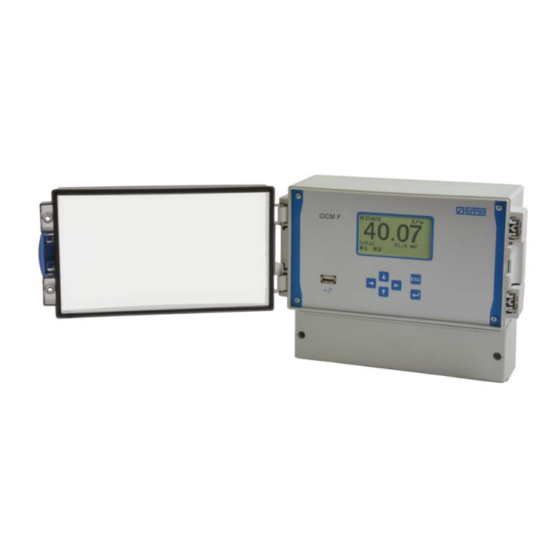
- Page 1 F L O W p e r m a n e n t Instruction Manual Flow Measurement Transmitter OCM F Firmware Revision: 4.00 Original manual: German / 16.02.2018 Rev. 05 / 06.04.2018...
- Page 2 Fax: +33 (0)3 88071697 Phone: +562 2266 8119 info@nivus.fr chile@nivus.com www.nivus.fr www.nivus.com NIVUS U.K. Ltd. Wedgewood Rugby Road Weston under Wetherley Royal Leamington Spa CV33 9BW, Warwickshire Phone: +44 (0)8445 3328 83 nivusUK@nivus.com www.nivus.com page 2 OCM F - rev. 05 / 06.04.2018...
-
Page 3: Copyrights And Property Rights
Copyrights and property rights Copyrights and property rights This document and its contents are proprietary to NIVUS GmbH and are not to be repro- duced or copied without the express written permission of NIVUS GmbH. Violations oblige to compensation. Important Note This manual may exclusively - even in parts - be copied or translated in any other way with the express written consent of NIVUS GmbH. -
Page 4: Table Of Contents
Transmitter Installation and Connection ..........19 14.1 General ..................19 14.2 Enclosure Dimensions ..............20 14.3 Hints on how to avoid electrostatic discharge (ESD) ....21 14.4 Transmitter Installation ..............21 page 4 OCM F - rev. 05 / 06.04.2018... - Page 5 Table of Contents 14.5 Electrical Installation ..............22 14.5.1 Transmitter Connection ..............22 14.5.2 KDA Sensor Connection ..............25 14.6 Power supply of OCM F .............. 28 14.7 Overvoltage Protection Precautions ..........29 14.8 Controller Mode ................32 14.8.1 General .................... 32 14.8.2 Construction of Measurement Section and Control Section ....
- Page 6 Maintenance interval ..............99 31.2 Customer Service Information ............. 99 Cleaning .................... 100 32.1 Transmitter ................100 32.2 Sensors ..................100 Dismantling/Disposal ................. 100 Accessories ..................101 Table “Manning-Strickler Coefficients” Index Approvals and Certificates page 6 OCM F - rev. 05 / 06.04.2018...
-
Page 7: General
Technical Instruction for Doppler Sensors • Installation Instruction for Correlation and Doppler Sensors These manuals are provided with the auxiliary units or sensors and/or are available as down- load on the NIVUS homepage. OCM F - rev. 05 / 06.04.2018 page 7... -
Page 8: Signs And Definitions Used
Colour code for wires and single conductors The abbreviations of colours, wire and components follow the international colour code ac- cording IEC 757. black transparent blue white GNYE green/yellow green yellow brown grey pink page 8 OCM F - rev. 05 / 06.04.2018... -
Page 9: Safety Instructions
Contains information that should be highlighted. Indicates a potentially damaging situation which can result in a damage of the product or an object in its environment. Note Contains information and facts. OCM F - rev. 05 / 06.04.2018 page 9... -
Page 10: Warning Notices On The Product (Option)
The entire measurement system shall be installed and put into operation by trained expert personnel only. Integrated buffer battery The exchange of the integrated buffer battery shall be carried out by NIVUS staff or per- sonnel authorised by NIVUS only. Otherwise the guarantee expires. page 10... -
Page 11: Liability Disclaimer
All operations on the device which go beyond installation or connection measures in principle shall be carried out by NIVUS staff or personnel authorised by NIVUS due to reasons of safe- ty and guarantee. -
Page 12: User's Responsibilities
For installation and commissioning the conformity certificates as well as the test certificates issued by the respective authorities shall be followed. The Ex version of the OCM F is adjusted solely to NIVUS Doppler sensors Type KDA re- garding the intrinsically safe system review according to EN60079-25. -
Page 13: Product Specification
In case of enquiries and ordering replacement parts it is important to specify article number as well as the serial number of the respective transmitter or sensor. This ensures correct and quick processing. OCM F - rev. 05 / 06.04.2018 page 13... -
Page 14: Specifications
Outputs 3x 0/4...20 mA, load 500 Ohm, 12 bit resolution, accuracy better than 0.1 % (after adjustment) 5 switchable relays, loadable up to 230 V AC / 2 A (cos.ϕ 0.9) page 14 OCM F - rev. 05 / 06.04.2018... - Page 15 The type examination certificate can be found at the end of this manual. Sensors Observe the specifications of the according sensors as described in the respective instruction manuals or technical descriptions. OCM F - rev. 05 / 06.04.2018 page 15...
-
Page 16: Configuration
OCM F Configuration 11.1 Device Types The OCM F transmitter is available in different versions as shown in the overview table below. The transmitters primarily vary in terms of power supply and Ex-protection. The current type of device is indicated by the article number, which can be found on a weatherproof label on the bottom of the enclosure. -
Page 17: Reception Inspection
Do not expose the system to heavy shocks or vibrations. Use the original packaging for transport. 11.6 Return In case of a required reshipment return the unit at customer cost to NIVUS GmbH in Ep- pingen using the original packaging. Insufficiently franked shipments will not be accepted. -
Page 18: Functional Principle
Functional Principle 12.1 In General The OCM F is a permanent measurement system for flow measurement and flow control. The device is designed to be used primarily in slight to heavy polluted media with various compositions. It can be operated in partial and permanent filled channels and pipes with vari- ous shapes and dimensions. -
Page 19: Installation And Connection
During installation works keep in mind that electronic components may be irreversibly dam- aged due to electrostatic discharge. Therefore avoid intolerably high electrostatic charge dur- ing installation by implementing appropriate grounding measures. OCM F - rev. 05 / 06.04.2018 page 19... -
Page 20: Enclosure Dimensions
Should this be the case try to clean the door using spirit or car polish. If these measures should not be successful the clear view door can be replaced by NIVUS at extra costs. 14.2 Enclosure Dimensions Fig. -
Page 21: Hints On How To Avoid Electrostatic Discharge (Esd)
Installation and Connection 14.3 Hints on how to avoid electrostatic discharge (ESD) When connecting the OCM F the following warnings and hints shall be observed right as the warnings and hints found in the according chapters on installation. WARNING Disconnect the unit from mains power Disconnect the instrument from mains power before you begin to carry out maintenance, cleaning and/or repair works (expert personnel only). -
Page 22: Electrical Installation
It is not allowed to remove the front panel. Tightness of the terminal housing Water or dirt must not leak into the terminal housing. Seal the housing with the supplied lid and both screws respectively. page 22 OCM F - rev. 05 / 06.04.2018... - Page 23 Plug connectors with screw terminal connection (terminal 24…54): Screw terminal connection; wire up to 1.5 mm², strand up to 1.5 mm², Screwdriver blade width max. 2.5 mm Fig. 14-2 Terminal housing, Ex version OCM F - rev. 05 / 06.04.2018 page 23...
- Page 24 'DC +'/'DC –' (clamps 4 and 5) is conducted through an internal extra common mode filter and 'DC +' can be enabled/disabled by using the DC switch. Fig. 14-3 Clamp wiring transmitter OCM F page 24 OCM F - rev. 05 / 06.04.2018...
-
Page 25: Kda Sensor Connection
The diagram below applies in case of connecting a KDA flow sensor: Fig. 14-4 KDA wedge or pipe sensor, Type K0 or R0 (Non-Ex) Fig. 14-5 KDA combi sensor with integrated pressure measurement cell, Type KP (Non-Ex) OCM F - rev. 05 / 06.04.2018 page 25... - Page 26 If the level measurement is carried out by a 2-wire probe (NivuBar, NivuCompact 2-wire echo sounder or similar), which is supplied by the OCM F, please follow the wiring diagram below: Fig. 14-8 Ext.
- Page 27 Installation and Connection Fig. 14-9 NIVUS i-Series sensor for level measurement in Ex-Zone 1 Do not connect to intrinsically safe clamps The Zone 1 Ex approval of i-Series sensors is guaranteed thanks to protection encapsula- tion category “Ex m”. These sensors hence must not be connected to the intrinsically safe terminal clamps (Ex ia) of the transmitter.
-
Page 28: Power Supply Of Ocm F
OCM F 14.6 Power supply of OCM F Depending on the type of OCM F used, it can be supplied with 100…240 V AC or with 24 V DC (see chapter “10 Specifications”). The two slide switches (located above the termi- nals) serve as additional power switches. -
Page 29: Overvoltage Protection Precautions
For effective protection of the OCM F transmitter it is necessary to protect power supply and mA inputs and outputs. NIVUS recommends •... - Page 30 Instruction Manual OCM F Fig. 14-15 Overvoltage protection for power supply and analog in-/outputs page 30 OCM F - rev. 05 / 06.04.2018...
- Page 31 Installation and Connection Fig. 14-16 Overvoltage protection for KDA velocity sensor Non-Ex version Fig. 14-17 Overvoltage protection for KDA velocity sensor Ex version OCM F - rev. 05 / 06.04.2018 page 31...
-
Page 32: Controller Mode
The assignment of the relays for the controller cannot be modified. Selection of sufficient contact material The input current on the digital inputs of the OCM F is 10 mA. Please ensure contact relia- bility by selecting sufficient contact materials on the end switch of the control slide valve. -
Page 33: Construction Of Measurement Section And Control Section
Instruction for Correlation and Doppler Sensors” manual. Hand slide valve Ultrasonic sensor i-Series Regulation-slide valve Install pipe sensor using nozzle or tapping saddle Fig. 14-18 Setup of a controlled system such as a discharge control OCM F - rev. 05 / 06.04.2018 page 33... -
Page 34: Connection For Controller Operation
Instruction Manual OCM F 14.8.3 Connection for Controller Operation Fig. 14-19 Wiring diagram for controller operation page 34 OCM F - rev. 05 / 06.04.2018... -
Page 35: Control Algorithm
In case of using a 4…20 mA signal as external setpoint, this signal can be monitored for ca- ble breaks and short circuits. If errors should occur the OCM F is going to access the internal setpoint (→ in case of using external 4…20 mA setpoints and error monitoring always set the internal setpoint additionally!). -
Page 36: Initial Start-Up
• span and function of analog and digital outputs The OCM F user surface was designed in a way that even unfamiliar users are able to easily set up basic settings in dialog mode which ensure reliable device operation. For extensive programming, difficult hydraulic conditions, in case of absence of expert staff or if a setup and error protocol is required, the programming should be carried out by the manu- facturer or an expert company which is authorised by the manufacturer. -
Page 37: Operator Panel
Abort button Confirmation button Fig. 17-1 Operator panel Display The OCM F has a large back-lit graphic display with a resolution of 128x64 pixels. This en- sures a comfortable communication mode for the user. Name of measurement place Flow Total Relay status Fig. - Page 38 Indication of current data on h-crit Calibration and Simulation: Definition of maximum and minimum measurable flow velocity Calibration of level Calibration of analog outputs Simulation of analog and digital outputs Simulation of the calculated volume page 38 OCM F - rev. 05 / 06.04.2018...
-
Page 39: Operation Basics
Press once to toggle from RUN menu to overview menu (main menu) Activate a submenu >ENTER< Accept and store values, units and so on Table 5 Functions of the control keys OCM F - rev. 05 / 06.04.2018 page 39... -
Page 40: Parameter Setting
PIN. After correctly entering the PIN the modified parameters are accepted and the unit will restart. The OCM F is ready for operation again after approx. 20…30 seconds. Options at the end of setting parameters: •... - Page 41 Fig. 20-5 Secondary screen of the main display The display will return to the previous screen either if pressing >ENTER< again or ap- prox. 30 seconds after the last key action. OCM F - rev. 05 / 06.04.2018 page 41...
-
Page 42: Operation Mode (Run)
>ENTER< after erasing. Time of day totalising Day values (and unit) Current day with cumulated total 24 h-day totals Date Fig. 21-1 Display day values / info page 42 OCM F - rev. 05 / 06.04.2018... - Page 43 “Ext. set point” - if external set point is not available “Control unit” - in case of error of the control unit (“Valve OPEN”, “Valve CLOSED”, “Valve TORQUE”) “Battery” - transmitters buffer battery empty OCM F - rev. 05 / 06.04.2018 page 43...
-
Page 44: Display Menu (Extra)
Pressing the key >right< and >left< will take you through the pages. Among other information these pages contain information on last parameter setting/parameter change as well as mains power failure which might have been occurred. page 44 OCM F - rev. 05 / 06.04.2018... - Page 45 Example: a total of 10 litres is indicated as 10.00 (xx.yy) instead of x.yyy Fig. 22-4 Selecting the display format OCM F - rev. 05 / 06.04.2018 page 45...
- Page 46 - Specify new total value - Confirm with Enter key - Enter system-PIN and confirm - New total value is shown in the main screen page 46 OCM F - rev. 05 / 06.04.2018...
- Page 47 Make a note of the system-PIN and store it in a safe place. >Service-Code< This menu point is for the NIVUS commis- sioning service only. >Reset all pins< If the system-PIN should get lost a PUK (Per-...
-
Page 48: Parameter Menu (Par)
After the submenu >Name< has been selected the basic setting “NIVUS” will come up. There is a cursor blinking below the first digit which can be modified. Underneath the measurement place name you can find a table with 20 lines containing all uppercase and lowercase letters as well as a large number of special characters (see Fig. - Page 49 3r Egg (radius) Rectangular (profile height and width) U-Profile (profile height and diameter) Trapezoid (profile height, profile width down/up, max. chn. height) Custom shape h/A (channel shape(s)) Custom shape h/b (channel shape(s)) OCM F - rev. 05 / 06.04.2018 page 49...
- Page 50 There may be different distances between individual level points. Furthermore it is not re- quired to use all of the 32 breakpoints possible. The OCM F however is going to use a linear- ization function between the breakpoints. Decrease the distance between breakpoints in case of heavy and irregular fluctuation within the area.
- Page 51 These values are going to be considered as absolute values and therefore affect positive as well as negative velocities. Both setting options of low-flow suppression have an OR relation between each other. Fig. 23-9 Selection low-flow volumes OCM F - rev. 05 / 06.04.2018 page 51...
-
Page 52: Parameter Menu "Level
Fig. 23-11 Example in case of external level sensor Basically determine the sensor type (Fig. 23-12) first. Fig. 23-12 Determine the sensor type page 52 OCM F - rev. 05 / 06.04.2018... - Page 53 Pressure Level measurement by a KDA combi sensor which is directly con- nected to OCM F according Fig. 14-5. Offset installation e. g. due to sedimentation or high dirt load is possible. Level measurement in case of flooding is possible as well.
- Page 54 Ext. sensor Level measurement by external Ex 2-wire sensor supplied by (Ex) OCM F e. g. a pressure probe, type NivuBar Plus or echo sounder type NivuCompact). Connect as described in Fig. 14-10. Fig. 23-16 Sensor type 4: 2-wire probe Ex Please select the appropriate level measurement method prior to planning the facility.
-
Page 55: Information On How To Connect I-Series Sensors
20 mA (full) – 100 % 0.125 0.300 0.300 0.500 span distance to sensor face in m Measurement span (value at 20 mA) 2.875 14.5 Table 6 i-Series sensors measurement range OCM F - rev. 05 / 06.04.2018 page 55... -
Page 56: Parameter Menu "Velocity
This section enables to set and the digital input signals “switch OPEN”, “switch CLOSE” and “torque close”. The OCM F requires these inputs for regulator operation. The function >Stop v-measurement< is exclusively available for digital input 4. -
Page 57: Parameter Menu "Analog Output
>Level< Output of analog signal which is proportional to measured filling level. >Velocity< Output of analog signal which is proportional to mean flow velocity averaged from meas- ured individual velocities. OCM F - rev. 05 / 06.04.2018 page 57... - Page 58 As soon as e. g. the sensor is going to be removed from the medium or no velocity can be measured at all (Fig. 23-21/3), signal first slopes gently getting steeper subsequently. page 58 OCM F - rev. 05 / 06.04.2018...
- Page 59 ENTER. A tick will appear as soon as the function has been confirmed. Pressing ENTER once more will deactivate the function again. Leave this point by pressing ESC (see Fig. 23-25). OCM F - rev. 05 / 06.04.2018 page 59...
-
Page 60: Parameter Menu "Relay
Select parameter >func- tion< in order to indicate the available functions. Toggle between relays using the >left< and >right< arrow keys. page 60 OCM F - rev. 05 / 06.04.2018... - Page 61 The relay will not de-energise before the time set is expired and the limit value is pre- sent yet. If the value falls below the limit threshold for a moment the cycle will begin anew. OCM F - rev. 05 / 06.04.2018 page 61...
- Page 62 (to be set). >Relay mode<, See >Flow limit relay< >ON point<, >OFF point<, >ON delay<, >OFF delay<, >Name< Fig. 23-30 Submenu impulse page 62 OCM F - rev. 05 / 06.04.2018...
- Page 63 Choose the desired function with the >up< or >down< arrow keys and confirm by pressing ENTER. A tick will appear as soon as the function has been confirmed. Pressing ENTER once more will deactivate the function again. OCM F - rev. 05 / 06.04.2018 page 63...
-
Page 64: Parameter Menu "Control Unit
“14.8 Controller Mode”. Qualified personnel It is absolutely necessary to have sound knowledge on control technology to correctly and safely set the controller. Fig. 23-33 Submenu >Internal set point< page 64 OCM F - rev. 05 / 06.04.2018... - Page 65 Parameter Setting >Not active< The function is disabled. >Internal set The set point is determined in the OCM F. point< >Max. flow rate< Enter the max. possible flow rate of the measurement place here in l/s. This value is required for improved system control.
- Page 66 Depending on application, this parameter shall be set approx. 60…80 % higher than the set point. Before setting this parameter observe waves at the measurement place as well as the unit’s page 66 OCM F - rev. 05 / 06.04.2018...
- Page 67 >Time delay< This is the time to elapse before the position control comes into effect in case of errors. The adjustable range is 0…240 seconds. Fig. 23-34 Submenu >External set point< OCM F - rev. 05 / 06.04.2018 page 67...
-
Page 68: Parameter Menu "Setup Parameter
Enables a general reset of the measurement transmitter. Entering the system-PIN will cause the transmitter to execute a general reset. The unit will be in initialising mode subsequently which requires the operation language to be set. page 68 OCM F - rev. 05 / 06.04.2018... -
Page 69: Parameter Menu "Storage Mode
Additional system setting options are going to be revealed as soon as a special code has been entered. This parameter is reserved for NIVUS service personnel as the settings require comprehensive ex- pert knowledge and are not needed for common applications. -
Page 70: Signal Input/Output Menu (I/O)
The currents actually present on the output terminals are not shown here. Only the signal received by the D/A-converter for output is indicated here. This menu cannot be used to detect and to view external incorrect connections. page 70 OCM F - rev. 05 / 06.04.2018... -
Page 71: I/O Submenu "Relay
Plug the USB stick into the USB slot located next to the keypad. >Store NivuSoft< >All< All readings saved in the internal memory are transmitted to USB stick in txt-format. The readings can be easily imported into NivuSoft using the “Quick Import” function. OCM F - rev. 05 / 06.04.2018 page 71... - Page 72 USB stick. File name: CHGPARAM_DATE_TIME.csv >Load parameter< All parameter files on the USB stick are shown. The file chosen using ENTER will be loaded to the transmitter. page 72 OCM F - rev. 05 / 06.04.2018...
-
Page 73: I/O Submenu "Measure Data
Velocity of sound resulting from medium temperature Amplification value of sensor Amplification mode of sensor Measured medium temperature Quality of velocity measurement Firmware version of sensor Fig. 24-7 Status of sensors and velocity evaluation OCM F - rev. 05 / 06.04.2018 page 73... -
Page 74: I/O Submenu "V-Histogram
Doppler Sensors”). Quality = very good Quality = good Frequency distribution = very good Frequency distribution = good Quality = satisfactory Quality = none Frequency distribution = satisfactory Frequency distribution = none page 74 OCM F - rev. 05 / 06.04.2018... -
Page 75: I/O Submenu "External Level
Current regulating time calculated from “Qdff” [sec./4] Time how long activated relay remains energised [Sek./4] Remaining cycle time [sec.] Status of three digital inputs Status of both relays Fig. 24-11 Control unit selection OCM F - rev. 05 / 06.04.2018 page 75... -
Page 76: I/O Submenu "Test Control Unit - Manual Mode
This menu allows to adjust level measurements. Values from -1000…+1000 mm (39.4 in) can be entered. This adjustment is required only if the level measurement utilises a pressure measurement cell. Fig. 25-2 Submenu level page 76 OCM F - rev. 05 / 06.04.2018... -
Page 77: Cal Submenu "Flow Velocity
If the maximum value is set to “0” it is not possible to measure and to issue the positive velocity! If the minimum value is set to “0” it is not possible to measure and to issue the negative velocity! OCM F - rev. 05 / 06.04.2018 page 77... - Page 78 Example: enter 0.085 m under “h-crit” in case of using a sensor in- stallation height of 0.02 m. >h-crit. min< The flow velocity will not be calculated below “h_crit. min” and hence will be set to 0. page 78 OCM F - rev. 05 / 06.04.2018...
- Page 79 Manual (if a reference value can be determined) Qualified personnel Comprehensive expert knowledge is required to properly utilise these parameters. We therefore recommend the NIVUS commissioning service or thorough device training. OCM F - rev. 05 / 06.04.2018 page 79...
- Page 80 (see Fig. 25-6/4). >h manual< Entry of current level >v manual< Entry of current flow velocity Fig. 25-10 Manually setting v-crit determination page 80 OCM F - rev. 05 / 06.04.2018...
-
Page 81: Cal Submenu "Analog Outputs
Calibration of analog outputs DANGER Personal injury The simulation of OCM F outputs will access any following facility areas without any safety locking measures! Simulations may only be carried out by NIVUS expert personnel or by specialist companies trained by NIVUS in cooperation with qualified operator personnel. -
Page 82: Cal Submenu "Relays
Select the desired relays to simulate by using the >up< or >down< arrow keys. Use ENTER to directly energise or de-energise the cho- sen relay. Energised relays will de-energise as soon as you exit the menu. Fig. 25-13 Relay simulation page 82 OCM F - rev. 05 / 06.04.2018... -
Page 83: Cal Submenu "Simulation
Simulated height/level Simulated flow velocity Simulated medium temperature Calculated simulated flow value Programmed relay activated by simulation Analog output signals Fig. 25-14 Simulation mode OCM F - rev. 05 / 06.04.2018 page 83... -
Page 84: Parameter Tree / Menus Available
Channel shape h/b shape(s) Sludge height Level Sensor type Pressure trans. Mounting height Constant Value level External Range 4-20 mA sensor Value at 0/4 mA Value at 20 mA Offset Damping page 84 OCM F - rev. 05 / 06.04.2018... - Page 85 Error input mask (only with error mode active) Value at error Hold old case (only value with error Constant mode active) 0 mA Constant 3,6 mA Constant 4,0 mA Constant 21 mA OCM F - rev. 05 / 06.04.2018 page 85...
- Page 86 OFF delay (only with relay function active) Name (only with relay function ac- tive) Impulse dura- tion (only with relay function impulses) Volume im- pulse (only with relay function im- pulses) page 86 OCM F - rev. 05 / 06.04.2018...
- Page 87 (only with active controller) Max. pulse time (only with active controller) P-factor (only with active controller) Level quick close (only with active controller) Flow quick close (only with active controller) OCM F - rev. 05 / 06.04.2018 page 87...
- Page 88 Setup pa- System reset rameter Service mode Service code Damping Stability Storage Memory 1 min mode cycle Format of numbers Unit system metric Date format TT/MM/JJJJ Time format page 88 OCM F - rev. 05 / 06.04.2018...
- Page 89 External set- point (only with active controller ext. setpoint) External level (only with external sen- sor) Control unit (only with active con- troller) Manual ctrl- mode (only with active controller) OCM F - rev. 05 / 06.04.2018 page 89...
- Page 90 OCM F Calibration menu (CAL) Default settings Level Calibration Velocity Min. velocity -4,0000 Max. velocity 4,0000 h-v- calibration v-crit- Manual determination Manning- Strickler h-crit. 0,75 v-crit. at h_crit. Analog Calibration outputs page 90 OCM F - rev. 05 / 06.04.2018...
- Page 91 Language German English French Polish Display Contrast 50 % System time Info Set date Set time Date format TT.MM.JJJJ Time format Modif. totalizer Modify PIN System-PIN 2718 Service-Code Reset all pins OCM F - rev. 05 / 06.04.2018 page 91...
-
Page 92: Troubleshooting
If measurement fails only with the flow direction reverted → go to CAL-Flow Velocity – min. + max. value: set min value to -6.0 m/s. Programming Completely check the transmitter parameter set- tings. page 92 OCM F - rev. 05 / 06.04.2018... - Page 93 Increase damping. Sensor Check sensor position (towards flow direction, horizontal installation) and correct installation depth. Check sensor for sedimentation or obstructions. OCM F - rev. 05 / 06.04.2018 page 93...
- Page 94 Check output control function in calibration menu. Programming Check if relay outputs are enabled. Check if outputs are correctly assigned to respec- tive output channels. Check additional values such as impulse parame- ters, limit values, logic etc. page 94 OCM F - rev. 05 / 06.04.2018...
- Page 95 Let NIVUS replace the built-in buffer battery. memory shows no is empty Attention: replacement must be carried out only by parameters NIVUS or personnel authorised by NIVUS. Other- wise the warranty will expire. OCM F - rev. 05 / 06.04.2018 page 95...
-
Page 96: Verification Of The Measurement System
• Check power supply on the OCM F. The according slide switch on the board must be engaged (see Fig. 14-12). The main screen must be visible on the transmitter display. -
Page 97: Verification Of External Level Measurement
Then compare output signal as well as measurement span of the external measurement with the analog input signal and the measurement span of the OCM F in PAR menu as well as in I/O menu and adjust accordingly if required. -
Page 98: Verification Of Flow Velocity Measurement
In various countries it may be necessary to carry out regular maintenance with comparative measurements in particular applications to comply with official regulations. If desired, NIVUS is going to carry out all required verifications, hydraulic and technical assessment, calibration, troubleshooting and repairs if an according maintenance agreement has been contracted. -
Page 99: Maintenance And Cleaning
Wear protective clothing. Maintenance 31.1 Maintenance interval The transmitter OCM F is conceived to be virtually free of calibration, maintenance and wear. (requirements of the Industrial Safety Regulations are unaffected). NIVUS recommends having the entire measurement system inspected by the NIVUS cus- tomer service once per year. -
Page 100: Cleaning
This symbol indicates that the Directive 2012/19/EG on waste electrical and electronic equipment requirements shall be observed on the disposal of the equipment. The unit con- tains a buffer battery (Lithium coin cell), which must be disposed separately. page 100 OCM F - rev. 05 / 06.04.2018... -
Page 101: Accessories
Maintenance and Cleaning Accessories KDA sensor Ultrasonic Doppler sensor for flow velocity or combi sensor for flow velocity and level for connection to OCM F KDA-… USB stick USB stick 8 GB, for readout of parameter settings and measure- ment values using the USB interface of OCM F... -
Page 102: Table "Manning-Strickler Coefficients
Old wooden formwork Brickwork, no joints, finished Dry stone wall, less carefully manufactured Soil material, smooth (fine-grained) Rougher surfaces are difficult to measure under hydraulic aspects and hence are not described here page 102 OCM F - rev. 05 / 06.04.2018... -
Page 103: Index
Power consumption ............14 Flow velocity detection ..........18 Power supply ............14, 28 Frequency histogram ............. 98 Precautions ..............10 Front panel .............. 21, 22 Protection ..............14 Functional principle ............18 OCM F - rev. 05 / 06.04.2018 page 103... - Page 104 User’s responsibilities ............ 12 UV radiation ..............20 Wall mount enclosure ..........20, 21 Weatherproof cover ............19 Wedge sensor ............... 13 Wires colour code ..............8 Zero point drift ............... 77 page 104 OCM F - rev. 05 / 06.04.2018...
-
Page 105: Approvals And Certificates
Approvals and Certificates Approvals and Certificates OCM F - rev. 05 / 06.04.2018 page 105... - Page 106 Instruction Manual OCM F page 106 OCM F - rev. 05 / 06.04.2018...
- Page 107 Approvals and Certificates OCM F - rev. 05 / 06.04.2018 page 107...
- Page 108 Instruction Manual OCM F page 108 OCM F - rev. 05 / 06.04.2018...
- Page 109 Approvals and Certificates OCM F - rev. 05 / 06.04.2018 page 109...
- Page 110 Instruction Manual OCM F page 110 OCM F - rev. 05 / 06.04.2018...
Need help?
Do you have a question about the OCM F and is the answer not in the manual?
Questions and answers