Table of Contents
Advertisement
Quick Links
F L O W p e r m a n e n t
Instruction Manual
Flow Measurement Transmitter
NivuFlow 650
Firmware Revision: 2.4.x
Revised manual
Document revision: rev. 01 / 29.06.2020
Original Manual: German / rev. 01 as of 19.05.2020
I n s t r u m e n t a t i o n
f o r
W a t e r
I n d u s t r y
NIVUS GmbH • Im Taele 2 • Germany-75031 Eppingen • Internet: www.nivus.com
Phone +49 (0) 7262 9191-0 • Fax +49 (0) 7262 9191-999 • E-Mail: info@nivus.com
Advertisement
Table of Contents

Related Manuals for Nivus NivuFlow 650


Summary of Contents for Nivus NivuFlow 650
- Page 1 W a t e r I n d u s t r y NIVUS GmbH • Im Taele 2 • Germany-75031 Eppingen • Internet: www.nivus.com Phone +49 (0) 7262 9191-0 • Fax +49 (0) 7262 9191-999 • E-Mail: info@nivus.com...
- Page 2 Yeon-su-gu, www.nivus.de INCHEON, Korea 21984 Phone +82 32 209 8588 Fax +82 32 209 8590 korea@nivus.com NIVUS Sp. z o.o., Poland www.nivus.com ul. Hutnicza 3 / B-18 81-212 Gdynia, Poland Phone +48 (0)58 7602015 Fax +48 (0)58 7602014 NIVUS Vietnam biuro@nivus.pl...
-
Page 3: Copyrights And Property Rights
Copyrights and property rights Copyrights and property rights This document and its contents are proprietary to NIVUS GmbH and are not to be reproduced or copied without the express written permission of NIVUS GmbH. Violations will be liable for compensation. -
Page 4: Document Modifications
Instruction Manual NivuFlow 650 Document modifications Rev. Modifications Editor in Date charge Complete revision: many features and functions added, layout redesi- 29.06.2020 gned etc. First version based on the German document 21.12.2015 page 4 NF 650 - rev. 01 / 29.06.2020... -
Page 5: Table Of Contents
Contents Contents COPYRIGHTS AND PROPERTY RIGHTS DOCUMENT MODIFICATIONS GENERAL About this manual ................... 12 Applicable documentation .................12 1.2 Signs and definitions used ................12 Abbreviations used .....................13 Connections and Operating Elements ..........13 Power Supply .....................13 NivuFlow Operating Elements ................14 Tasks of control elements ...................14 Interfaces ......................15 SAFETY INSTRUCTIONS General: Used Symbols and Signal Words ........... - Page 6 Instruction Manual NivuFlow 650 PRODUCT SPECIFICATION 15 Product Construction and Overview ............. 22 15.1 Dimensions of enclosure ..................23 15.2 Connectable sensors ..................24 15.3 Device identification ..................24 16 Specifications ..................25 17 Configuration ..................26 17.1 Device Types .....................26 17.2 Additionally bookable Function Licences ............27 FUNCTIONAL DESCRIPTION 18 Operating Ranges ..................
- Page 7 Contents 23 Controller operation (function additionally bookable as licence) ..47 23.1 General ......................47 23.2 Control Section Setup ..................49 23.3 Regulator Mode Wiring Diagram ................50 23.4 Control Algorithm ....................50 24 Overvoltage Protection Measures ............51 24.1 Overvoltage Protection for Power Supply ............52 24.2 Overvoltage Protection for mA-Inputs/Outputs ..........53 24.3...
- Page 8 Instruction Manual NivuFlow 650 31 Parameter Functions ................75 31.1 Main Menu ......................75 31.2 Overview: Functions Top Menu Level ..............75 31.2.1 Application Menu / MP1 / MP2 / Combi ............75 31.2.2 Data Menu .....................76 31.2.3 System Menu ....................77 31.2.4 Communication Menu ..................78 31.2.5...
- Page 9 Contents 32.5 Setting parameters in Inputs and Outputs (analog and digital) Menu ....98 32.5.1 Analog Inputs ....................98 32.5.2 Analog Outputs ....................99 32.5.3 Digital Inputs ....................102 32.5.4 Digital Outputs ....................103 32.6 Setting Parameters in Q-Control Menu (function bookable as extra licence) ..105 32.7 Setting Parameters in Diagnostics Menu ............106 33 Data Parameter Menu ................
- Page 10 Instruction Manual NivuFlow 650 MAIN DISPLAY 38 General overview .................. 132 38.1 Display Flow in measurement places 1 and 2 ..........134 38.2 Display Level in measurement places 1 and 2 ..........134 38.3 Display Velocity in measurement places 1 and 2 ..........135 38.4...
- Page 11 Contents INDEX CREDITS AND LICENSES 52 List of references of the licenses and codes used ......172 APPROVALS AND CERTIFICATES NF 650 - rev. 01 / 29.06.2020 page 11...
-
Page 12: General
READ CAREFULLY BEFORE USE. KEEP IN A SAFE PLACE FOR LATER REFERENCE. This instruction manual for the flow measurement transmitter NivuFlow 650 is for the intended use of the device only. This manual is oriented exclusively to qualified expert personnel. -
Page 13: Abbreviations Used
General Abbreviations used Colour code for wires and single conductors The abbreviations of colours, wire and components follow the international colour code accor- ding to IEC 60757. black brown orange yellow green blue violet grey white pink turquoise GNYE green/yellow gold silver Connections and Operating Elements... -
Page 14: Nivuflow Operating Elements
Instruction Manual NivuFlow 650 NivuFlow Operating Elements The NivuFlow is operated completely in dialogue mode supported by the graphs on the display. To select individual menus and submenus use the rotary pushbutton as well as both function keys. Graphic display... -
Page 15: Interfaces
General Diagnostics of the signal analysis ƒ • Menu >Data< Selection of Trend, Total and Day totals ƒ Within the programming of multiple inputs/outputs or when programming several v-paths, the right function key is used to jump from one input/output or v-path to the next. You will find a description on how to use the control elements in Sect. -
Page 16: Safety Instructions
Instruction Manual NivuFlow 650 Safety Instructions General: Used Symbols and Signal Words Valuation of the accident level The general warning symbol indicates the risk of personal injuries or death. In the text section the general warning symbol is used in conjunction with the signal words described below. -
Page 17: Warning Notices On The Product (Option)
Integrated buffer battery The integrated buffer battery may only be exchanged by NIVUS staff or personnel authori- sed by NIVUS. Infringements lead to a limitation of the warranty (see Sect. “5 Warranty”). NF 650 - rev. 01 / 29.06.2020 page 17... -
Page 18: Warranty
Limitation of warranty In the event of non-compliance with the safety instructions and instructions in this document, the companies of the NIVUS group of companies reserve the right to limit the warranty. Liability Disclaimer The legally associated companies and subsidiaries of NIVUS group assume no liability •... -
Page 19: Use In Accordance With The Requirements
The user alone bears any risk. The NivuFlow 650 transmitter and associated sensor system is designed for continuous flow measurement of slightly contaminated to clear, pure water-based liquids in partly or fully filled pipes, channels or water bodies. -
Page 20: Personnel Requirements
Instruction Manual NivuFlow 650 Personnel requirements Installation, commissioning and maintenance shall be executed only by personnel meeting the demands as follows: • Expert personnel with relevant training and appropriate qualification • Personnel authorised by the plant operator Qualified personnel within the context of this documentation or the safety notes on the product itself are per- sons who are sufficiently familiar with installation, mounting, starting up and operation of the product and who have the relevant qualifications for their work;... -
Page 21: Delivery, Storage And Transport
Otherwise, the same rules apply with regard to external influences as for storage (see Sect. “12 Storage”). 14 Return In case of a required reshipment return the unit at customer cost to NIVUS GmbH in Eppingen using the original packaging. Insufficiently franked shipments will not be accepted! NF 650 - rev. -
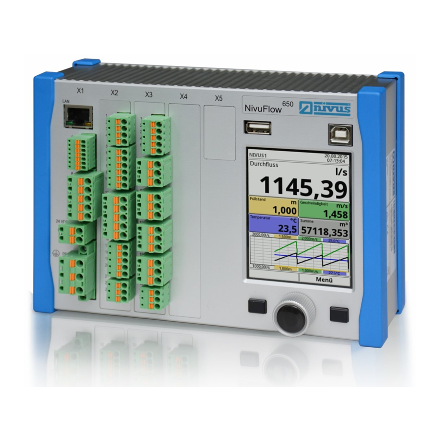
Page 22: Product Specification
USB-A interface (data transfer, parameter backup, device update) USB-B interface (service) Graphics display Left function key Rotary pushbutton Right function key DIN rail fastening Fig. 15-1 Device setup NivuFlow 650 enclosure type E0/E1 page 22 NF 650 - rev. 01 / 29.06.2020... -
Page 23: Dimensions Of Enclosure
Product specification 15.1 Dimensions of enclosure Fig. 15-2 Dimensions of NivuFlow 650 enclosure type E0 Fig. 15-3 Dimensions of field enclosure NivuFlow NF 650 - rev. 01 / 29.06.2020 page 23... -
Page 24: Connectable Sensors
NivuFlow 650 15.2 Connectable sensors You can find the connectable NIVUS sensors and their data or information on their mounting in the documents “Technical Instructions Transit Time Sensors” and “Installation Instructions Transit Time Sensors”. These documents are delivered with the ordered sensors. Alternatively, they are available for download at www.nivus.com. -
Page 25: Specifications
Product specification 16 Specifications Power supply 100...240 V AC, -15 % / +10 %, 47...63 Hz or 10...35 V DC Supply connection Plugged and screwed tension clamp terminal block Max. power consumption AC: 30 VA / DC: 20 W Typ. power consumption 1x relay energised, 230 V AC: 14 W (rounded), up to eight transit time sensors 1 MHz Enclosure... -
Page 26: Configuration
Instruction Manual NivuFlow 650 Data memory Internal 1.0 GB, for programming and readings memory; via USB stick frontside read out Storage cycle 30 seconds to 5 minutes - HART (Slave) via AO1 Communication - Modbus TCP via networks (LAN/WAN, Internet) -
Page 27: Additionally Bookable Function Licences
Measurement transmitter to connect NFE extension modules (up to 32 paths), 1x air-ultrasonic sensor OCL, 7x DI, 5x DO, 5x AI, 4x AO; multiple I/Os for communication and control jobs available by purcha- se of additional licences; DIN rail, prepared for mounting into NIVUS field enclosure, Type ZUB0 NFW0 Power supply 100...240 V AC... -
Page 28: Functional Description
The NivuFlow 650 is used in partly and fully filled pipes, channels and water bodies of various geometries and dimensions. The device types TR and TZ can be equipped with controller functions in the form of a 3-step controller to drive slide valves or other actuators at extra charge. -
Page 29: Functional Principle
There is no measurable flow available. The NivuFlow 650 works with both clamp-on sensors and wetted sensors. The clamp-on sen- sors are installed on the outside of the pipe. In this case the transit time through the pipe wall is calculated and considered. -
Page 30: Flow Calculation
Instruction Manual NivuFlow 650 The more paths are used in the asymmetrical or disturbed profile and distributed in the flow cross-section, the more accurately the flow can be determined. Sensor 1, path 1 Sensor 2, path 1 Sensor 1, path 2 Sensor 2, path 2 Pipe diameter (at sensor installation in an angle of 45°) -
Page 31: Installation And Connection
NivuFlow 650 Type E0 not suitable for installation in NIVUS field enclosure It is not possible to install a NivuFlow 650 Type E0 in a NIVUS field enclosure unless the transmitter is converted to a Type E1 unit. The conversion and the modification of connec- tions can be carried out by NIVUS. -
Page 32: Choosing The Installation Place
Make sure that any existing disconnectors (power switch) remain easily accessible during installation. The measurement transmitter can also be installed in field enclosures or similar. NivuFlow 650 is not suitable to be installed directly on site without protective measures due to protection degree. -
Page 33: Field Enclosure Fastening And Preparing Electric Installation
The fastening material is not part of the standard delivery but should be specified and chosen individually depending on the place of installation. The NIVUS field enclosure can be installed permanently once the appropriate place of installa- tion has been chosen. A basic condition is safe, durable and stable installation. - Page 34 Readability may be strongly impai- red due to the changes to the protective film. New clear view covers can be purchased from NIVUS for an extra charge and can be easily replaced by the user.
-
Page 35: Electrical Installation
Installation and Connection 21 Electrical Installation DANGER Danger from electrical current Disconnect the unit from mains power. Working on electric wiring may cause electric shock. Observe electric information provided on the nameplate. Non-observance may result in personal injuries. Note Observe the national installation regulations. Ü... - Page 36 [mm²] 0.25...2.5 Wire cross-section (flexible) with ferru- 0.25...2.5 Undefined 0.25...0.5 le with plastic sleeve in [mm²] Table 21-1 Wire cross-section The measurement transmitter NivuFlow 650 is available in different Types: • Type T2 • Type TR • Type T4 • Type TM •...
-
Page 37: Plans Of Terminal Connections
Operate the instrument with the tension clamp terminal block screwed on only. Non-observance may result in personal injuries. Fig. 21-2 Terminal connections NivuFlow 650 Type T2 NF 650 - rev. 01 / 29.06.2020 page 37... - Page 38 Instruction Manual NivuFlow 650 Fig. 21-3 Terminal connections NivuFlow 650 Type TM page 38 NF 650 - rev. 01 / 29.06.2020...
- Page 39 Installation and Connection Fig. 21-4 Terminal connections NivuFlow 650 Type T4 NF 650 - rev. 01 / 29.06.2020 page 39...
- Page 40 Instruction Manual NivuFlow 650 Fig. 21-5 Terminal connections NivuFlow 650 Type TR page 40 NF 650 - rev. 01 / 29.06.2020...
- Page 41 Installation and Connection Fig. 21-6 Terminal connections NivuFlow 650 Type TZ NF 650 - rev. 01 / 29.06.2020 page 41...
-
Page 42: Switching On Voltage Supply
Instruction Manual NivuFlow 650 21.3 Switching on voltage supply Depending on the type of NivuFlow used the unit can be powered with 100...240 V AC (-15 / +10 %) or with 10...35 V DC. 24 V DC connection 230 V AC connection Fig. -
Page 43: Power Supply Ac
Installation and Connection 21.3.2 Power supply AC DANGER Danger from electrical current Do not operate the unit if the terminal clamp blocks above the screw flange are not tightly screwed. The terminal block X1 (terminals 15...17) for connecting the earth conductor and AC power supply is an integral part of the device. -
Page 44: Relays
Instruction Manual NivuFlow 650 21.4 Relays Contact reliability deteriorates if the minimum make/break current is lower than specified. Observe the wiring and switching specifications of the relays in Sect. “16 Specifica- tions”. DANGER Danger from electrical current – Measures to prevent accidental contacts Contact protection according to the requirements as specified in EN 61010-1:2010 is not guaranteed in the event of relay voltages >150 V due to the testing pin terminal of the relay... -
Page 45: Installation Of Clamp-On Sensors
Installation and Connection 22.2 Installation of Clamp-On Sensors Clamp-on sensors allow for contactless measurement in closed and full pipelines. Here the sensors are clamped from the outside onto pipes. The instrumentation will not impact the liquid and will not change the medium's flow profile. A detailed description of the sensors and their installation can be found in the “Technical Instructions Transit Time Sensors”... -
Page 46: Cable And Cable Length For Connecting The Sensors
The cables connected to the sensors at the factory must be used for the total distance between the NIVUS sensors and the NivuFlow transmitter. The signal cable is not intended for laying directly in the ground. If the signal cable is to be laid in soil, concrete, etc., it must be laid in protective pipes or protective hoses with a sufficiently... -
Page 47: Connection To/Via Extension Module Nfe
To implement volume regulation it is necessary to have a NivuFlow 650 Type TR or TZ trans- mitter available. Other types are not suitable since they do not have enough inputs and outputs to drive control slide valves or are not equipped with the corresponding software for controller functions. - Page 48 Use a knife gate valve or a pipe slide valve electric control actuator and 3-step control as control element. Slides with analog control signals cannot be driven. NIVUS recommend the following actuating times (runtime between fully opened and com- pletely closed slide valve) for the slide valve selection: •...
-
Page 49: Control Section Setup
Installation and Connection Analog input AI5 is predefined for input of an external setpoint. Assignment of inputs/outputs to regulator defined The assignment of inputs and outputs to the regulator is fixed and cannot be changed. Guarantee reliable contacting of limit switches by choosing the suitable contact material of the limit switches on the control slide valve. -
Page 50: Regulator Mode Wiring Diagram
Instruction Manual NivuFlow 650 23.3 Regulator Mode Wiring Diagram Fig. 23-2 Wiring diagram regulator mode NF650 Type TZ/TR 23.4 Control Algorithm Activate all messages For slide valve control via digital inputs always use all three messages. Activating only one message may lead to disturbances during regulator operation. -
Page 51: Overvoltage Protection Measures
Since comprehensive knowledge in control technology is required to correctly program the regulator, more detailed explanations are not needed here. In case of doubt contact the NIVUS commissioning service. 24 Overvoltage Protection Measures Transmitters and their terminal connections should, where the risk demands it, be protected against potential voltages surges (such as lightning strikes in transmission lines) by additional overvoltage protection measures. -
Page 52: Overvoltage Protection For Power Supply
NivuFlow 650 24.1 Overvoltage Protection for Power Supply NIVUS recommends type EnerPro 220Tr surge arrestors (for a 100-240 V AC power system) and EnerPro 24Tr (for 24 V DC power supply) for the mains supply. Observe the connection direction Observe the non-reversed connection (p-side to transmitter) as well as a correct, straight wiring supply. -
Page 53: Overvoltage Protection For Ma-Inputs/Outputs
Installation and Connection 24.2 Overvoltage Protection for mA-Inputs/Outputs NIVUS recommends type DataPro 2x1 24/24 Tr surge arrestors for mA-inputs and mA-outputs. Observe the connection direction Observe the non-reversed connection (p-side to transmitter) as well as a correct, straight wiring supply. Ground (earth) must lead to the unprotected side. -
Page 54: Overvoltage Protection For (Transit Time) Sensor Connectors
Overvoltage protection for (transit time) sensor connectors 24.4.1 Basic protection - equipotential bonding cable NIVUS recommends that an equipotential bonding cable is used to connect the sensor enclo- sure to the control cabinet/transmitter ground as a basic protection measure for the transit time sensors’... - Page 55 The “EnerPro” overvoltage protector may also be installed inside the control cabinet, but the separate earth connector “G” must be retained. The combination with “P” or “C” is very risky in the event of overvoltage. NIVUS recommends that the earth connectors are separated to guard against overvoltages.
- Page 56 Instruction Manual NivuFlow 650 All other input/output signals and input/output voltages leaving the control cabinet must also be considered in relation to overvoltages. In most cases, there is no galvanic isolation and compensating currents can flow. In applications particularly at risk of overvoltage, an additional low-capacitance isolating transformer can further reduce the sensitivity to overvoltage events.
- Page 57 Installation and Connection Do not reverse protected (p) and unprotected sides of overvoltage protection Fig. 24-8 Modified overvoltage protection 3. Proceed with the overvoltage protection as described in Sect. “24.4.2 Extended protection - overvoltage protection “SonicPro T”” where the top terminals are used for further connection to the transmitter.
-
Page 58: Operation Start-Up
The user interface of the NivuFlow is easy to understand. Users can make all required basic settings themselves. In the case of the following requirements let either one of the legally associated companies or subsidiaries of NIVUS group or an expert company authorised by NIVUS set the parameters: • Extensive programming tasks •... -
Page 59: Operation Basics
Operation start-up 26 Operation Basics The complete operation of the NivuFlow is handled via control elements (see Sect. “2.2 NivuFlow Operating Elements”). Two control buttons and one rotary pushbutton are available for the setting of parameters and to input required data. The display at any time provides information on where you currently are within the menu struc- ture and which entries you are about to modify. -
Page 60: Use/Entry Using The Letter Block
Instruction Manual NivuFlow 650 The transmitter in the background operates with the settings which have been entered at the beginning of the parameter setting. The following request is prompted on the display not before the current parameter setting has been finished and confirmed. -
Page 61: Use/Entry Using The Numeric Keypad
Operation start-up A shift key can be found at the bottom left of the keypad (Fig. 26-4 no. 3). • The functions of the shift key are: Upper case ƒ Lower case ƒ Special characters ƒ Digits ƒ • These settings allow individual names (e.g. of the measurement place). •... -
Page 62: Menus
• Recall basic information on the transmitter and the connected sen- System sors such as serial no., version, article no. and many more (needed in the event of queries from NIVUS) • Settings such as language, time and data format and units can be modified in the >country settings<... - Page 63 Operation start-up Engage pipeline experts Wet sensors shall be installed only by a pipeline company or a plumber. The tightness of pipes and the compressive strength of the installation must be guaranteed at any time. For the measurement place basically the parameters below must be set: •...
-
Page 64: Start-Up Examples
DIN ISO 748 standard “Hydrometry - Measure- ment of liquid flow in open channels using current-meters or floats” (ISO 748:2007)”. This section explains two parameter setting examples for usual NivuFlow 650 applications step by step. - Page 65 Start-up Examples • Sensors: Level: i-series sensor, type i-06 ƒ Flow: rod sensors, type NOS-V2; path height: 40 % of usual filling level ƒ • Position and mounting height of level sensor (3.30 m) due to conditions on site • Level monitoring, standard level 2 m Fig.
- Page 66 Another menu opens up which can be used to specify e.g. the speed of sound within the medium. Tip: Various speeds of sound can be found on the Internet or contact NIVUS GmbH. 6. Use the selection menu to specify the medium to measure and to select/specify the current medium temperature.
- Page 67 Start-up Examples 2. Confirm modified parameters and path rearrangement. The display shows “Initial- ised!” after confirmation with >Yes<. The transmitter switches to the >Application< menu. Ü Â Procedure for the selection of level sensors and the specification of mounting values: 1.
-
Page 68: Extended Parameter Setting
Instruction Manual NivuFlow 650 The >Distance across< and >Distance along< fields on the display indicate the distance between both sensors. The indicated distance is always the clearance between both sensors. All other parameters are read-only or remain to be set to default. -
Page 69: Example 2: Measurement In Open Waters
The second measurement example is performed in an open water body. The used transit time sensors are NIVUS hemispheres since they are very well suited for slanted installation on river banks. The related banks should be stable and should not tend to changes. -
Page 70: Setting Parameters Of A Multi-Path System In >Channel
Instruction Manual NivuFlow 650 29.2 Setting Parameters of a Multi-Path System in >Channel< Application Specifications: • Open channel, width 5 m • Stable, inclined banks • No sedimentation on the channel bottom • Path arrangement “Chordal X” • 4 paths •... - Page 71 Another menu opens up which can be used to specify e.g. the speed of sound within the medium. Tip: Various speeds of sound can be found on the Internet or contact NIVUS GmbH. 6. Use the selection menu to specify the medium (water) to measure and to select/ specify the current medium temperature.
- Page 72 Instruction Manual NivuFlow 650 Fig. 29-3 Accept modified measurement place parameters 2. Confirm modified parameters and path rearrangement. The display shows “Initial- ised!” after confirmation with >Yes<. The transmitter switches to the >Application< menu. Ü Â Procedure for the selection of level sensors and the specification of mounting values: 1.
- Page 73 Start-up Examples Fig. 29-5 Specify v-Sensors The >Direction< is suggested by the transmitter for both paths compatibly. This setting can be retained. The >Distance across< and >Distance along< field on the display indicates the distance between both sensors. The indicated distance is always the clearance between both sensors. All other parameters remain to be set to default.
-
Page 74: Setting Parameters
>Enter< button. The transmitter leaves mode with the parameterization without entering a password. If a number is displayed next to the service key, the transmitter is in service mode. This is usually the case when a NIVUS service technician has access to the transmitter. 30.3 Change Password S ee also Sect. -
Page 75: Parameter Functions
Setting Parameters Important Note Share your password with authorised persons only! If you should write down your password store it in a safe place. Should your password get lost contact the NIVUS GmbH. 31 Parameter Functions 31.1 Main Menu The transmitter parameters can be set using a total of five to eight (depending on the type) setup menus within the first menu level. -
Page 76: Data Menu
Instruction Manual NivuFlow 650 The sensors used as well as information on the mounting position are specified here. Moreover the required analogue and digital inputs and outputs are defined here: • Functions • Measurement ranges • Measurement spans • Limit values The Q-regulator parameters are set in >Application<... -
Page 77: System Menu
Setting Parameters The functions below are available: • Graphic representation of measurement values • List of the 100 previous 24h-day totals • Communication and transmission options for internal files • Format external USB stick • Transmission of parameters set from USB stick and back •... -
Page 78: Communication Menu
Details on TCP and Modbus RTU, • Settings for scaling of flow rate, level, velocity, temperature, analog and sum • and there is a diagnostic option (the data available there are important for the NIVUS service). S ee Sect. “35 Communication Parameter Menu”. 31.2.5 Display Menu Fig. -
Page 79: Connections Menu
Setting Parameters 31.2.6 Connections Menu Fig. 31-7 Connections menu This menu is only available for transmitter types T4, TM and TZ, as it deals with • the transmitter configuration comprising multiple measurement points and/or • the connection of extension modules NFE. The two DSP cards (digital signal processor cards) and the analog and digital inputs and outputs of the respective measurement points are assigned here. -
Page 80: Active
Instruction Manual NivuFlow 650 Fig. 32-1 Parameter menu application 32.1.1 Active This option is only available for transmitter types T4 and TM, as it deals with the transmitter configuration comprising multiple measurement points. The measurement point is enabled by checking the box. If no check mark is set, the measure- ment point is disabled, nothing is displayed and it cannot be parameterized. -
Page 81: Path Arrangement
Setting Parameters 32.1.3 Path Arrangement Depending on the channel profile set either all or only a part of the path arrangements below are available: • Diametral \ (circular pipes only) • Diametral V (circular pipes only) • Diametral VV (circular pipes only) •... -
Page 82: Medium Temperature
Tip: Lists providing various speeds of sound can be found on the Internet or contact your local distributor or NIVUS GmbH. 32.1.7 Medium Temperature The medium temperature must initially be entered once and as accurately as possible; it is required for correctly initializing the transmitter. - Page 83 Setting Parameters Fig. 32-4 Selecting the channel profile / Setting the units Pipe This selection is suitable for round pipes, however can be used for half shells featuring a filling level of 50 % max. Deformed pipes featuring asymmetric height/width ratio can be set using the ellipsoid geome- try selection.
- Page 84 NivuFlow Mobile as well as about hydrologic ambient conditions. We recommend letting the NIVUS commissioning service or a company authorised by NIVUS do the programming works. In this profile you define the reference point/zero point yourself. Mostly, the maximum level or the water surface on one bank or channel side is determined as zero point.
- Page 85 Setting Parameters Drawing required A true to scale drawing is required to set the channel parameters. Ü Â Procedure: 1. Draw a vertical auxiliary line onto the drawing in the channel centre. 2. Then draw horizontal auxiliary lines on the distinct points where the profile chan- ges.
- Page 86 Instruction Manual NivuFlow 650 height breakpoints may vary. Not all of the 32 breakpoints need to be necessarily entered in order to define the profile since the transmitter linearises between indivi- dual breakpoints. In case of large irregular changes of the channel dimensions select a lower dis- tance between breakpoints in this section.
-
Page 87: Channel Profile Offset
Setting Parameters 32.1.9 Channel profile Offset Regarding the individual channel profiles specifying the >Channel Profile Offset< allows inclu- ding a local level for the respective measurement place. Default setting: 0.000 m This setting is not possible for channel profile “Channel (local datum)” since this setting here can be adjusted for the individual measurement spots (in the table). -
Page 88: V-Determination Low Levels
ƒ or backwater ƒ or low medium quantities standing still at zero flow rates ƒ expected within the channel, NIVUS GmbH recommend to deactivate the function by page 88 NF 650 - rev. 01 / 29.06.2020... - Page 89 After the first measurement using real values >v-manual< can be set to a new value, however, this modification does not become effective before the values for >v-ma- nual< have been reset in the service menu. If necessary contact the NIVUS hotline. Default setting: 0.000 m/s •...
-
Page 90: Low-Flow Suppression
Instruction Manual NivuFlow 650 32.1.14 Low-Flow Suppression This parameter is used to suppress lowest movements or apparent flow rates. The main area of use is the measurement of discharge volumes in permanently filled constructions. Ü Â Check >Active< and enter the desired value in >Q suppressed< or >v suppressed<. -
Page 91: Stability
Setting Parameters Input the value in steps of one second. Default setting: 30 s 32.1.16 Stability The stability parameter defines the period the transmitter bridges values without having valid measurement events (e.g. in case of invalid flow velocity or level readings) available. During this period the transmitter operates using the latest valid reading. -
Page 92: Setting Parameters In H-Sensors Menu
Instruction Manual NivuFlow 650 32.3 Setting parameters in h-Sensors Menu After setting the measurement place parameters one or more level sensors need to be defined and the according measurement ranges must be specified. The level sensor parameters can be set in >h-Sensors< submenu. -
Page 93: Overlapped
The level is measured by using an external 2-wire sensor supplied by the transmitter. • i-Series sensor Connection of NIVUS i-Series ultrasonic sensors on analog input AI1. Air-ultrasonic NIVUS • The level is measured from the top down using an air-ultrasonic sensor. -
Page 94: Deviation (Abs.)
Instruction Manual NivuFlow 650 The overlap is indicated on the screen by offset colour bars next to the channel (Fig. 32-11). Fig. 32-11 Overlapping: Selection and display 32.3.3 Deviation (abs.) The >Deviation (abs.)< parameter is indicated/selectable only if at least two level sensors are connected and overlap is activated. -
Page 95: Fallback
The transmitter shows the sensor mounting distances after the specifications are completed. Up to eight flow rate sensors (4 paths) can be directly connected to a NivuFlow 650 transmit- ter, depending on the type. Up to 64 sensors (32 paths) can be indirectly connected via one or more extension modules (see Sect. -
Page 96: Sensor Mounting Position
• >NIS-V200R (300mm)<, >NIS-V200R (200mm)<, >NIS0V200RL<, >NOS-V2005<, >NOS-V3005<, >NOS-V4005<, >NOS-V20B<, >NOS-V30B<, >NIS-V280K<, >NIS- V300K<, >NOS 500kHz< and >NOS 200kHz< The values for the NIVUS sensors themselves are pre-set and cannot be selected or changed. • >User defined< The values for >Angle<, >Frequency<, >Offset< must be specified. -
Page 97: Weighting
The weighting value depends on the application and the sensor position. Such applications require extensive fluid mechanics knowledge and require the use of NIVUS commissioning personnel or an authorized specialist company. >Weighting< By modifying the >Weighting< value the involved paths can be weighted and prioritised diffe- rently. -
Page 98: Setting Parameters In Inputs And Outputs (Analog And Digital) Menu
Instruction Manual NivuFlow 650 32.5 Setting parameters in Inputs and Outputs (analog and digital) Menu This menu is to define the function of the analog as well as digital inputs and outputs. Other parameters such as measurement and output spans, offsets, limit values, error reactions etc. -
Page 99: Analog Outputs
Setting Parameters Fig. 32-16 Analog inputs: Activation / Ext. Reading / Flow Currently the analog inputs can be used for external readings (such as temperature in °C) and for flow measurement. The transmitter hence can be utilised as an extra data logger for readings from other systems. - Page 100 Instruction Manual NivuFlow 650 Fig. 32-17 Analog outputs: Activation / Flow / Path velocity >Flow< • The application flow rate (calculated from average flow velocity and wetted cross section) is available on the selected analog output. Selection/Input Options: ƒ Output range: >0-20 mA< or >4-20 mA<...
- Page 101 Setting Parameters Value at 0 mA: manual input Value at 20 mA: manual input Value at error: >0 mA< or >Hold value< or >3.5 mA< or >21.0 mA< • >External reading< Possibly linearised measurement values available at the analog input are available here.
-
Page 102: Digital Inputs
Instruction Manual NivuFlow 650 32.5.3 Digital Inputs The number of digital inputs depends on the type (see Sect. “17.1 Device Types”). The available digital inputs are shown in the top right corner of the display. The digital inputs can be selected successively by pressing the right-hand control key >Tab<. -
Page 103: Digital Outputs
Setting Parameters • >Impulse counter< The system counts and saves the number of oncoming signals on the digital input. The impulses are counted by detecting the status change of the digital input (1->0 or 0->1). Selection/Input Options: ƒ Edge: >rising< (status change “0” to “1”) or >falling< (status change “1” to “0”) Label: manual input •... - Page 104 Instruction Manual NivuFlow 650 Absolute: check Value at error: >Off< or >On< or >Hold Value< Delay: manual input Hold: manual input • >Limit contact level< If the entered upper level limit value is exceeded, a digital signal is output. If the value falls below the lower level limit, this digital signal is reset = hysteresis function to avoid output jitter.
-
Page 105: Setting Parameters In Q-Control Menu (Function Bookable As Extra Licence)
Setting Parameters • >Limit contact external read.< If the entered upper external measured value limit is exceeded, a digital signal is out- put. If the value falls below the lower external measured value limit, this digital signal is reset = hysteresis function to avoid output jitter. Selection/Input Options: ƒ... -
Page 106: Setting Parameters In Diagnostics Menu
Instruction Manual NivuFlow 650 function licence which subsequently needs to be unlocked. See Sect. “17.2 Additionally bookable Function Licences” and “34.5.3 Feature unlock”. To activate the regulator in this menu check the box next to >Active<. Per default the control is inactive. -
Page 107: Data Parameter Menu
Setting Parameters 33 Data Parameter Menu Fig. 33-1 Data menu The data menu contains all internally saved readings and is subdivided in six submenus. 33.1 Trend The Trend graph is a representational recorder function. Choosing the trend graph provides access to current and previously saved (historic) measurement data. The individual measurement points are shown at the top right of the display. - Page 108 Instruction Manual NivuFlow 650 The Date/Time Selection (Fig. 33-2 no. 1) can be found in the top area of the main screen. The line is highlighted blue and hence active. Ü Â Proceed as follows to select a specific point in time (historical measurement data): 1.
- Page 109 Setting Parameters If period >4 hours< is chosen the start of the representation depends on the selected point of time. Depending on the start time the representation begins: • 00:00 h • 04:00 h • 08:00 h • 12:00 h •...
-
Page 110: Total
Instruction Manual NivuFlow 650 33.2 Total The totals, divided into positive and negative totals, for the respective measurement points are displayed. In addition, the resettable totals are displayed and they can also be reset using the >Reset total< button. The individual measurement points are shown at the top right of the display. You can scroll between the measurement points with the Tab key. - Page 111 Setting Parameters viewed. If the transmitter should be shut down between two totalising events (< 24 hours) a total will be calculated by using measured values. Such a total is not equal to the real daily flow rate but corresponds to the rate measured by the transmitter while powered up. Should the transmitter be shut down before the next totalising event and remains shut down until the moment of the following totalising event (>...
-
Page 112: Usb Stick
Instruction Manual NivuFlow 650 33.4 USB stick Requirements to USB sticks: • USB 2.0 supported • FAT 32 format (or FAT 12 or FAT 16) • Maximum permissible memory 32 GB Working with USB stick: Ü Â Plug the USB stick into the USB slot located above the display. - Page 113 Setting Parameters Fig. 33-7 Transmission period / data depth / compression 9. To choose the desired data format turn the rotary pushbutton which opens a selec- tion menu. The formats txt and csv are available. 10. Press the rotary pushbutton to accept the data format. The selectable data depth comprises five possible levels: •...
- Page 114 Instruction Manual NivuFlow 650 • Operating hours This option saves only the operating hour totals, no individual values. The >Compress< function makes sense only when large data sets are to be transmitted. In such cases the selected files are zipped as “.zip” files. If the check mark is set, you can also select >Ram<...
- Page 115 Setting Parameters app1_t_air [°C] Standard, Average calculated air temperature in storage Extended, cycle when using an air-ultrasonic sensor Expert app1_h_isensor [m] Extended, Average calculated air temperature in storage Expert cycle when using an i-Series sensor p1_v [m/s] Extended, Path velocity Expert p1_g_srch [dB] Extended,...
-
Page 116: Data Storage
Instruction Manual NivuFlow 650 33.5 Data storage This submenu can be used to modify the storage cycle and to erase the internal data memory. Fig. 33-10 Data storage Setting options for the storage cycle: • 30 s, 1 min, 2 min, 5 min, 10 min, 15 min... -
Page 117: System Parameter Menu
Setting Parameters always be overwritten (ring memory). Ü Â Turn the rotary pushbutton to the right to scroll down the table and to the left to scroll up again. It is possible to view older day totals as well. A prerequisite to view older values is that the unit has run for a longer period. -
Page 118: Operation) Language
Instruction Manual NivuFlow 650 Fig. 34-2 Language settings / language / date format 34.2.1 (Operation) Language The following languages or alternative languages are currently available: • English, German, French, Italian, Spanish, Portuguese, Swedish, Danish, Finnish, Polish, Hungarian, Romanian, Czech and Russian 34.2.2... -
Page 119: Data Units
Setting Parameters Units system Available units: • Metric • English • American The adjustable units depend on the selected units system: • In metric system - e.g. liter, cubic metre, cm/s etc. • In English system - e.g. ft, in, gal/s etc. •... -
Page 120: Time/Date
Instruction Manual NivuFlow 650 NIVUS Header When the check mark is set, a NIVUS logo is displayed/printed on the output table. Without a check mark there is no NIVUS logo and the table appears neutral. Units for storage • In metric system - e.g. l/s, m³/s, m³/d, cm/s etc. -
Page 121: Error Messages
Setting Parameters Fig. 34-6 Settings 34.4 Error messages Use this menu to recall the currently active queued error messages and to erase the error message memory. The memory is password protected to avoid unintentional deletion. Fig. 34-7 Error messages S ee also Sect. “Error Messages” starting at page 156. 34.5 Service This submenu contains the following functions:... -
Page 122: Service Level
Change (System) Password Default password: “2718” NIVUS recommend that this password is changed in order to protect the system from unau- thorised access. You are free to select any password with a maximum length of ten digits. For your own safety we recommend you share your password only with authorised individu- als. -
Page 123: Feature Unlock
Setting Parameters 34.5.3 Feature unlock Use this function to unlock (optionally available) features provided that they have been ordered from NIVUS. Ü Â Feature unlocking procedure: 1. Click button >Feature Unlock<. 2. In the menu opening up click >Feature Unlock< button. -
Page 124: Parameter Reset
Resetting the parameters to default settings 34.5.7 Update NivuFlow Upload a NivuFlow firmware stored on USB. Accessible in Service Level. Only in consultation with the companies of the NIVUS Group. 34.5.8 Update h-Sensor Upload a sensor firmware stored on USB. Accessible in Service Level. -
Page 125: Communication Parameter Menu
Furthermore the network integration can be set up here as well. The details will not be explained here. If you should not have the required IT skills we recommend you leave such tasks to IT specia- lists or the NIVUS commissioning personnel. Fig. 35-1 Communication 35.1... -
Page 126: Hart (Extra Function Bookable As Licence)
>FTPS<: Enable encrypted access via port 21 • >Password xxx<: Access to the various “drives” by the username; only parametrisation of the pass- words required; default setting: nivus • >Use own server certificate<: Check and choose file • >Router Mode (FTPS)<. -
Page 127: Modbus
HART 35.4 Modbus It is possible to integrate the transmitter into other systems via Modbus. The Modbus protocols are available upon request if required. Contact the NIVUS GmbH headquarters in Eppingen. Fig. 35-4 Modbus The functions below are available here: •... - Page 128 The scaling per digit is defined with “Scaling Total”. Specialist knowledge required These settings require extensive expert knowledge and require the use of NIVUS commis- sioning personnel or an authorized specialist company. Fig. 35-5 Programming measurement value scaling In >Diagnostics<...
-
Page 129: Display Parameter Menu
Adjust the backlight to the ambient conditions. Avoid setting the display too bright. In order to extend the display life NIVUS recommend to enable the automatic display dimming option here (dim light). The display will dim automatically if it has not been used for a certain time. - Page 130 Instruction Manual NivuFlow 650 Fig. 36-2 Total Type Total Type The totals types to be displayed are defined here. The following options are available: >Total<, >Positive total<, >Negative total<, >Daily mean<, >Daily mean pos.< and >Daily mean neg.<. Output fields The five main screen output fields (>Flow<, >Level<, >Velocity<, >Temperature<...
-
Page 131: Connections Parameter Menu
Setting Parameters The same procedure can be used to specify the desired number of decimal digits. Here a maximum of five decimal digits is possible. Note During setting the decimal digits observe the measurement accuracies of the sensors and the measurement units set. The temperature sensor e.g. -
Page 132: Main Display
The six-hour period begins once the password is entered and ends automatically. If a number is displayed next to the service key, the transmitter is in service mode. This is usually the case when a NIVUS service technician has access to the transmitter. See also Sect. “30.2 Save Parameters”. - Page 133 Main Display Date/Time Display range 1 (Output field 1 for flow rate) Display range 2 (Output field 2...5 for level, average flow velocity, medium temperature and total) Automatic scaling for display range 3 Display range 3 (trend graph on level, velocity, medium temperature and amount) Operating display for the assignment of the function keys Display range 4 (Output field 6 for flow rate of combined measurement place - Combi) Display range 5 (Output field 7...9 for the flow rates for measurement point 1 and measu-...
-
Page 134: Display Flow In Measurement Places 1 And 2
Instruction Manual NivuFlow 650 38.1 Display Flow in measurement places 1 and 2 Once the dialog window has been activated by pressing the rotary pushbutton you can use the pop-up menu to access the individual menus (Information, Diagnostics, Settings, Display and Error messages) (see Sect. -
Page 135: Display Velocity In Measurement Places 1 And 2
Main Display Fig. 38-4 Level: Pop-up menu and pages 38.3 Display Velocity in measurement places 1 and 2 Once the dialog window has been activated by pressing the rotary pushbutton you can use the pop-up menu to access the individual menus (Diagnostics, Settings and Display) (see Sect. “41 Diagnostics v-Paths”, “32.4 Setting parameters in v-Paths Menu”... -
Page 136: Display Temperature In Measurement Places 1 And 2
Instruction Manual NivuFlow 650 38.4 Display Temperature in measurement places 1 and 2 Once the dialog window has been activated by pressing the rotary pushbutton you can use the pop-up menu to access the menu Display (see Sect. “36 Display Parameter Menu”). -
Page 137: Display Trend/Hydrograph In Measurement Places 1 And 2
Main Display 38.6 Display Trend/Hydrograph in measurement places 1 and 2 Fig. 38-8 Trend/Hydrograph: Pop-up menu and page If more comprehensive and in-depth graphs should be required, the graph section can be selected directly. Here you can specify display period as well as the display range. Browse next or back within the selected period using the >Browse<... -
Page 138: Display Measurement Place 1/2 In Measurement Place Combi
Instruction Manual NivuFlow 650 38.8 Display Measurement Place 1/2 in measurement place Combi Once the dialog window has been activated by pressing the rotary pushbutton you can use the pop-up menu to access the individual menus (Diagnostics, Settings, Display and Error mes- sages) (see Sect. -
Page 139: Display Total In Measurement Place Combi
Main Display 38.9 Display Total in Measurement Place Combi Once the dialog window has been activated by pressing the rotary pushbutton you can use the pop-up menu to access the individual menus (Total, Day Totals and Display) (see Sect. “33.2 Total”, “33.3 Day Totals”... -
Page 140: Diagnostics
Necessarily observe the safety information on simulation on page 154. The Diagnostics section can also be very helpful for the operator for certain problems, but the main user is NIVUS Customer Service. page 140 NF 650 - rev. 01 / 29.06.2020... -
Page 141: Diagnostics H-Sensors
Diagnostics 40 Diagnostics h-Sensors Fig. 40-1 Menu Diagnostics h-Sensors This menu has a relation to the menu >Applications< / >h-Sensors<. Depending on the type and number of sensors defined here the sections are indicated in the corresponding colours. See Sect. “32.3 Setting parameters in h-Sensors Menu”. The Diagnostics screen shows the current level. -
Page 142: Diagnostics V-Paths
Instruction Manual NivuFlow 650 41 Diagnostics v-Paths Fig. 41-1 Menu Diagnostics v-Paths This menu is used to view information on hardware and current sensor/path data (see Fig. 41-1). There is no simulation available in this menu. The transmitter starts the menu with an overview. You can jump to the individual v-paths from this overview. -
Page 143: Inputs And Outputs (Analog And Digital)
Select the check mark to stop the currently selected path in order to align the signal. • >Firmware version< Information on the firmware version and the components is stored here. These speci- fications are relevant for NIVUS service personnel. • >Noise< >Upstream typical< ƒ... -
Page 144: Analog Inputs
Instruction Manual NivuFlow 650 42.1 Analog Inputs This menu can be used to indicate the current values on the transmitter inputs as well as the readings assigned to this value by using the measurement span. Fig. 42-2 Indication of analog input values 42.2... - Page 145 It is absolutely necessary to have a safety person available during execution! Disregarding may lead to personal injury or damage your facility. All legally associated companies and subsidiaries of NIVUS group herewith in advance refuse any responsibility for any possible damage to persons or objects at any extent due to...
-
Page 146: Digital Inputs
Instruction Manual NivuFlow 650 42.3 Digital Inputs This menu shows the signals oncoming on the digital inputs. Active digital inputs are checked. Fig. 42-4 Indication of digital inputs 42.4 Digital Outputs The adjusted digital output values are indicated here. Fig. 42-5 Indication of digital outputs A password protected simulation of digital outputs is available in this menu too. - Page 147 It is absolutely necessary to have a safety person available during execution! Disregarding may lead to personal injury or damage your facility. All legally associated companies and subsidiaries of NIVUS group herewith in advance refuse any responsibility for any possible damage to persons or objects at any extent due to...
-
Page 148: Control (Extra Function Bookable As Licence)
Instruction Manual NivuFlow 650 43 Q-Control (extra function bookable as licence) The diagnostics menu shows the current status of the Q control. This is a read-only section and parameters cannot be changed. See also Sect. “32.6 Setting Parameters in Q-Control Menu (function bookable as extra licence)”. -
Page 149: Signal Analysis
Diagnostics 44 Signal Analysis This menu is used to scan and to review the incoming signal from the sensor. Moreover the sensor function can be tested here. Fig. 44-1 Signal analysis Pulldown menu / search scan Select from the options below: •... - Page 150 Instruction Manual NivuFlow 650 >Scaling< of chart (Fig. 44-2) Time ƒ Distance ƒ >V-/H-Zoom< of chart Turn the rotary pushbutton to select the graphic and press to activate; Selection for V-Zoom: X1, X2, X5, X10, X20, X50 and X100 Selection for H-Zoom: Reduces the actual displayed/enlarged area within the graphic;...
- Page 151 Diagnostics Fig. 44-3 Signal scan envelope >Correlation< (Fig. 44-4) • Similarity and temporal shift of the received signals (delta t). >V-/H-Zoom< of chart Turn the rotary pushbutton to select the graphic and press to activate; Selection of V-Zoom: X1, X2, X5, X10, X20, X50 and X100 Selection of H-Zoom: Reduces the actual displayed/enlarged area within the graphic;...
- Page 152 Instruction Manual NivuFlow 650 Fig. 44-4 Correlation / Tx signal >Noise< (Fig. 44-5) • Display all noise (including noise interference) during signal analysis. >Direction< Upstream (towards flow direction) ƒ Downstream (in flow direction) ƒ Up-/Downstream ƒ >V-/H-Zoom< of chart Turn the rotary pushbutton to select the graphic and press to activate;...
- Page 153 Diagnostics • >Sensor test< (Fig. 44-6) Functional test (settling-time test; can also be performed in air) of the connected sensor. The data obtained is mainly used by the NIVUS customer service. >Direction< Upstream (towards flow direction) ƒ Downstream (in flow direction) ƒ...
-
Page 154: Simulation
It is absolutely necessary to have a safety person available during execution! Disregarding may lead to personal injury or damage your facility. All legally associated companies and subsidiaries of NIVUS group herewith in advance refuse any responsibility for any possible damage to persons or objects at any extent due to... - Page 155 Diagnostics Note The simulation mode access is password protected due to the reasons of safety mentioned above. Share your password with authorised and trained expert personnel only for reasons of personnel safety! Ü Â To start the simulation proceed as follows: 1.
-
Page 156: Error Messages
(3) Check air-ultrasonic sensor and cable for visible damage. (4) Check whether the parameters of the air-ultraso- nic sensor are correctly set. (5) Restart the transmitter via >System< / >Service<. (6) Contact NIVUS Hotline (serial number and exact error message required). Air-ultraso- Communi- Sensor response... - Page 157 (3) Check air-ultrasonic sensor and cable for visible damage. (4) Check whether the parameters of the air-ultraso- nic sensor are correctly set. (5) Restart the transmitter via >System< / >Service<. (6) Contact NIVUS Hotline (serial number and exact error message required). Air-ultraso- Faulty res- Sensor transmits...
- Page 158 (2) Check i-sensor and cable for visible damage. (3) Check whether the parameters of the i-sensor are correctly set. (4) Restart the transmitter via >System< / >Service<. (5) Contact NIVUS Hotline (serial number and exact error message required). Pressure Not suppor-...
- Page 159 (3) Check pressure sensor and cable for visible da- mage. (4) Check whether the parameters of the pressure sensor are correctly set. (5) Restart the transmitter via >System< / >Service<. (6) Contact NIVUS Hotline (serial number and exact error message required). Level Value too Level measure-...
- Page 160 (3) Check water-ultrasonic sensor and cable for visib- le damage. (4) Check whether the parameters of the water-ultra- sonic sensor are correctly set. (5) Restart the transmitter via >System< / >Service<. (6) Contact NIVUS Hotline (serial number and exact error message required). Water- Faulty res- Sensor transmits...
- Page 161 (1) Ensure that the power supply is stable on the or too low mains side. (2) Disconnect the transmitter from the mains for ten minutes and then reconnect. (3) Contact NIVUS Hotline (serial number and exact error message required). Hardware Logic (1.8V) Voltages too high...
- Page 162 (2) Ensure parameters are set correctly in the trans- mitter. (3) Restart the transmitter via >System< / >Service<. (4) If the error message appears again, contact the NIVUS hotline (serial number and exact error messa- ge required). Air tempe- Not suppor-...
- Page 163 (4) Check whether the parameters of the air tempera- ture sensor are correctly set. (5) Restart the transmitter via >System< / >Service<. (6) Contact NIVUS Hotline (serial number and exact error message required). Air tempe- No commu- Sensor does not...
- Page 164 (4) Check whether the parameters of the water tem- perature sensor are correctly set. (5) Restart the transmitter via >System< / >Service<. (6) Contact NIVUS Hotline (serial number and exact error message required). Water tem- Faulty res- Sensor transmits...
- Page 165 (3) Check the parameterized offset values using the cable information. (4) Check whether the sensor position deviates from the parameterized position. (5) Contact NIVUS Hotline (serial number and exact error message required). v-Path Value too Path check, mea- (1) Check the cable / transmitter connectors and sured value devia- check the cables for damage.
-
Page 166: Maintenance And Cleaning
General regulations for the operators of the measurement facility • Ambient conditions In addition to the annual inspection NIVUS recommends a complete maintenance of the mea- surement system by one of the legally associated companies and subsidiaries of NIVUS group after ten years at the latest. -
Page 167: Cleaning
Observe the local disposal regulations and laws. NIVUS GmbH is registered with the EAR, therefore public collection and return points in Germany can be used for disposal. -
Page 168: Installation Of Spare Parts And Parts Subject To Wear And Tear
Installation and/or the use of such products hence may negatively influence predetermined design characteristics of the measurement system or even lead to instrument failures. The legally associated companies and subsidiaries of NIVUS group cannot be held respon- sible for any damage resulting from the use of non-original parts and non-original accessories. - Page 169 Index Index Disposal of materials ......... 19 Disposal of products ........19 EC WEEE-Directive logo ......167 Accessories ..........168 Electrostatic discharge (ESD) ....31 Accident level ..........16 Environmental standards ......167 Approvals ..........173 Equipotential bonding cable Article number ........... 26 overvoltage protection ......
- Page 170 Instruction Manual NivuFlow 650 Residual-current-operated protective device ............35 Nameplate ..........24 Restart Names ............3 measurement ........123 Numeric keypad ........61 Return ............21 Revision of parameters ......61 Operating conditions ......... 25 Operating elements ......13, 14 Safety Instructions ........
- Page 171 Index Vibrations ..........21 v suppressed low-flow suppression ......90 Warning notices on the product (option) ......17 Warranty ............ 18 Web server communication ........125 Weighting ..........97 Wire cross section ........36 NF 650 - rev. 01 / 29.06.2020 page 171...
- Page 172 • Zlib (http://www.zlib.net) • Mini-XML (http://www.msweet.org) • Nano-X/nxlib (http://www.microwindows.org) • FLTK (http://www.fltk.org) • Appendix1: LGPL • Appendix2: MPL Questions concerning licenses If you have any questions concerning licenses refer to opensource@nivus.com page 172 NF 650 - rev. 01 / 29.06.2020...
- Page 173 Approvals and Certificates Approvals and Certificates NF 650 - rev. 01 / 29.06.2020 Page 173...
Need help?
Do you have a question about the NivuFlow 650 and is the answer not in the manual?
Questions and answers