
Related Manuals for Siel Safepower Evo 20


Summary of Contents for Siel Safepower Evo 20
- Page 1 _________ l � -' -------- - - SIEL SAFEPOWER Evo - руководство по эксплуатации. Юниджет Постоянная ссылка на страницу: https://www.uni-jet.com/catalog/ibp/on-line- ibp/siel-safepower-evo/...
- Page 2 For the entire life of the appliance This manual should be considered an integral part of the UPS unit INSTRUCTION MANUAL FOR SAFEPOWER-EVO SERIES IV306E Rev. 004 Siel S.p.A. Page 1 of 37 + 12 Tables, 14 Figures + FR Issued date: 2014-03-24...
-
Page 3: Table Of Contents
....................33 PTION NPUT OWER FACTOR CORRECTION 3: R UPS ..........33 PTION EDUCTION OF DISTORTION OF INPUT POWER FOR SIX PHASE IV306E Rev. 004 Siel S.p.A. Page 2 of 37 + 12 Tables, 14 Figures + FR Issued date: 2014-03-24... - Page 4 COMPLETE UPS SPECIFICATIONS: TABLE 7 MECHANICAL SPECIFICATIONS TABLE 8 OTHER DETAILS: TABLE 9 PARALLEL: TABLE 10 AVAILABLE OPTIONS: TABLE 11 EMERGENCY NETWORK FUSES: TABLE 12 IV306E Rev. 004 Siel S.p.A. Page 3 of 37 + 12 Tables, 14 Figures + FR Issued date: 2014-03-24...
-
Page 5: Important Warnings
Read the following warnings very carefully. Should you need any further information regarding this matter, please do not hesitate to contact SIEL S.p.A. This manual shall be considered an integral part of the UPS and be stored for the entire product life. - Page 6 AN UNINTERRUPTIBLE POWER SUPPLY IS CONNECTED ON THIS LINE. BEFORE PERFORMING ANY OPERATION ON THIS CIRCUIT TURN OFF ALL THE INPUT/OUTPUT SWITCHES. IV306E Rev. 004 Siel S.p.A. Page 5 of 37 + 12 Tables, 14 Figures + FR Issued date: 2014-03-24...
- Page 7 Never try to repair the machine on your own: refer to the manufacturer or to an authorized service centre. Any repair work made to the equipment not explicitly authorized or carried out by Siel, beside involving actual danger, implies the immediate cancellation of warranty. Siel shall not be liable for any consequent malfunctioning and for any arising loss or damages.
- Page 8 Maintenance 2 Maintenance shall always be carried out by SIEL S.p.A, in order to be sure that only new and genuine spare parts are used and that the machine can be updated in line with any technical development (according to the respective service contract).
- Page 9 Moreover, the user shall verify the device is installed according to the applicable regulations and to state-of-the-art procedures. SIEL S.p.A. strongly recommends to contact the technical department for further details. Product identification plate The product identification plate showing technical details and the appliance code and serial number, is accessible by opening the front door of the UPS unit (near the disconnecting switches).
- Page 10 Siel S.p.A.. Limitation of liability SIEL S.p.A. shall not be liable for any direct or indirect damages (including loss of profits or revenues) deriving from the malfunction of the device, even if SIEL S.p.A. was warned in advance of the possibility of such damages.
-
Page 11: Introduction
INTRODUCTION This instruction manual describes the Siel UPS “FLEXIPOWER-SAFEPOWER” series, manufactured by Siel SpA – Via I° Maggio 25 – Trezzano Rosa (Milan). These UPS units are identified by codes, the first two letters of which are: UG……… Furthermore, this manual applies to non-standard products based on the “Flexipower-Safepower”... -
Page 12: Description Of System
- A BATTERY (10) providing the energy required to operate the inverter in case of line voltage failure (the battery disconnecting switch (SB) must be included in the battery cabinet or premises). IV306E Rev. 004 Siel S.p.A. Page 11 of 37 + 12 Tables, 14 Figures + FR... - Page 13 «Description of the remote signalling systems». 1:In case of in-parallel operation, the appliances can be provided with a circuit for the sequential start of the UPS rectifiers IV306E Rev. 004 Siel S.p.A. Page 12 of 37 + 12 Tables, 14 Figures + FR...
- Page 14 SP117 which integrates this document). The version with the 24-pulse rectifier bridge may be supplied for UPSs with lower capacities on request (for further information, please contact Siel SpA). IV306E Rev. 004 Siel S.p.A. Page 13 of 37 + 12 Tables, 14 Figures + FR...
-
Page 15: Interactive Mode Of Operation
The Siel parallel does not require the exchange of any electrical type signal. Without going into operating details (for more details, the Siel staff are at your disposal) suffice it to say that the inverters are kept carefully synchronised so as to prevent exchanges of current between the machines. -
Page 16: Detailed Analysis Of Parallel Operation
In the event, due to maintenance, of an UPS unit being completely disconnected (disconnected from the mains, from the batteries and from parallel),or placed in test mode after disconnection from parallel (contact Siel) the remaining UPS units continue to power the load from inverter or mains as described previously. -
Page 17: Equipment
Some of these signals are repeated on the Functional diagram (Figure 5) where corresponding LEDs light up to provide a quick overview of the operation of the different equipment subassemblies. IV306E Rev. 004 Siel S.p.A. Page 16 of 37 + 12 Tables, 14 Figures + FR... - Page 18 5) Wrong battery voltage 6) Battery failure 7) Battery Overheating 8) Battery temperature probe fault INVERTER 9) Inverter overload 10) Phase R over current IV306E Rev. 004 Siel S.p.A. Page 17 of 37 + 12 Tables, 14 Figures + FR Issued date: 2014-03-24...
- Page 19 Room temperature and max temperature reached in the room. IV306E Rev. 004 Siel S.p.A. Page 18 of 37 + 12 Tables, 14 Figures + FR Issued date: 2014-03-24...
-
Page 20: Functional Diagram
UPS; the partner software of this dialogue can also pilot all the functions envisaged by the front panel of the machine. Siel offers two software programs, which take advantage of all opportunities given by the communication protocol. These programs, called EDMS and OCSystem3, cater for all possible control and signalling requirements. -
Page 21: Remote Signalling Systems
- The CN1 connector is an isolated communication port showing clean contacts; these are normally used by various software applications dedicated to monitoring and controlling the UPS (for further details, contact SIEL S.p.A.). The closing of a contact is equivalent to the occurrence of the event shown in figure 7. Figure 7 shows the standard connection. -
Page 22: Description Of Communication Fibre Optics
Customers wishing to use their own software to capture the signals and measurements provided by the UPS should send a written request to Siel S.p.A., who will then authorise and issue detailed specifications on the communication protocol. Also in this case, customers should remember to order the fibre optics/RS232 converter. -
Page 23: Installation
Visual inspection Prior to delivery, every UPS is carefully checked both electrically and mechanically. Always visually check a UPS after delivery for any transit damage, and immediately inform Siel S.p.A. if such damage is evident. Environmental considerations There are various environmental aspects to take into consideration, the most important being: Floor capacity The UPS occupies a small area and has a relatively heavy weight (see technical specifications). -
Page 24: Safety Considerations
New personnel must be trained before being authorised to operate the UPS. Batteries Siel build and supply reliable battery cabinets that do not require maintenance. The use of air- tight lead batteries rather than the "open-vented" batteries, which smell and need specific rooms, makes it possible to install them in cabinets adjacent to the UPS that are aesthetically matched. -
Page 25: Electrical Connections
The UPS is not provided with a disconnecting switch on the battery cable: install a box which contains a disconnecting switch with fuses or with a magneto-thermal circuit-breaker (contact Siel S.p.A. for supply if necessary) near the battery. Battery fuses are installed within the UPS. These fuses cannot protect against current coming from the battery in cases of cable short-circuiting. - Page 26 In the event of the battery compartment being positioned a long way from the UPS or a separate battery room being used, ask Siel S.p.A. for the optional optic fibre temperature sensor; with this sensor a distance of over 50 m can be reached between battery room and UPS.
-
Page 27: Maintenance
For message quick scrolling (at about 1 second intervals), keep the above keys pressed simultaneously. To access the Signalling control menu, press the <SHIFT> and <MENU> keys simultaneously. IV306E Rev. 004 Siel S.p.A. Page 26 of 37 + 12 Tables, 14 Figures + FR... - Page 28 To highlight the states / alarms press < SHIFT > + < > or < > cyclically. IV306E Rev. 004 Siel S.p.A. Page 27 of 37 + 12 Tables, 14 Figures + FR Issued date: 2014-03-24...
- Page 29 There are two more considerations: a) If zero is set as a number of weeks, the discharge test will only occur during the first week. IV306E Rev. 004 Siel S.p.A. Page 28 of 37 + 12 Tables, 14 Figures + FR...
-
Page 30: Start-Up And Subsequent Actions
(by key 1) to ensure signal display. [Repeat the operation on all the UPS units making up the system] IV306E Rev. 004 Siel S.p.A. Page 29 of 37 + 12 Tables, 14 Figures + FR Issued date: 2014-03-24... - Page 31 ON). Caution! If the battery is connected when the signal "Battery voltage OK" is not active, the protection fuse trips; this fuse can only be replaced by Siel personnel. The following indications will appear on the display: "Rectifier ON"...
- Page 32 7) Check that after about 30 seconds, LED 6 (load on mains) extinguishes and LED 4 (load on inverter) lights up. From now on, the load is supplied by the inverter. [from inverters connected in parallel] IV306E Rev. 004 Siel S.p.A. Page 31 of 37 + 12 Tables, 14 Figures + FR Issued date: 2014-03-24...
-
Page 33: Emergency Device (Epo) Operation
SIEL S.p.A., and only after finding and repairing the fault. Only the fuses of the reserve network (FR1, FR2, FR3, positioned immediately above the reserve network disconnecting switch S4) can trip in case of a load overcurrent;... -
Page 34: Option 1: Filtri Rfi
Option 1: Filtri RFI All the SIEL UPS units comply with European EN 62040-2 (EN50091-2) standard on electromagnetic compatibility. Filters that comply with more stringent regulations are available on request. -
Page 35: Option 10: Back-Feed Protection With Remote Switch
Option 13: Battery temperature reading kit. This Kit is necessary only if the UPS haven’t battery inside or if you usen’t Siel battery cabinet. This Kit communicates battery temperature to the UPS in order to change the recharging voltage. This sensor can be used only if the battery cabinet is located close to the UPS. -
Page 36: Option 17: Ocsystem Control System
Option 17: OCSystem control system This software has been developed by Siel to permit the control and management of the UPS units by means of a personal computer. Thanks to this software, up to 4 UPS units can be monitored, including of different powers. -
Page 37: Option 21: Power Adapter Autotransformers
Option 22: UPS used as frequency converter By means of this option, the Siel UPS units can be used as frequency converters (input 50Hz-output 60Hz or vice versa). . -
Page 38: Option 29: Versions Without Disconnecting Switches
If the plant includes input, output and bypass switches, you can use a version of UPS Safepower-EVO not featuring internal disconnecting switches. This option is available for sizes exceeding 160kVA-12F and 200kVA-6F. To define plant and switches configuration to be used, please contact the technical department of SIEL S.p.A. TECHNICAL SPECIFICATIONS... - Page 39 954 1271 1589 Output Phase S 954 1271 1589 Output Phase T 954 1271 1589 + Battery 841 1048 1250 1660 2075 - Battery 841 1048 1250 1660 2075 IV306E - SP133E Siel S.p.A. Form 1 - Page 1 of 1...
- Page 40 9b) Start-Up time 95,7 95,8 95,8 95,8 95,9 96,8 10) Efficiency 11) THD Note 1: 380Vac - 415Vac: Option Note 2: 60Hz: Option Note 3: PFC option (otherwise 0,83) IV306E - SP133E Siel S.p.A. Form 2 - Page 1 of 5...
- Page 41 95,6 10) Efficiency 11) THD (Note 4) Note 1: 380Vac - 415Vac: Option Note 2: 60Hz: Option Note 3: PFC option (otherwise 0,83) Note 4: Option (otherwise 9%) IV306E - SP133E Siel S.p.A. Form 2 - Page 2 of 5...
- Page 42 10-30 9b) Start-Up time 96,8 98,1 98,1 98,3 10) Efficiency 11) THD Note 1: 380Vac - 415Vac: Option Note 2: 60Hz: Option Note 3: PFC option (otherwise 0,83) IV306E - SP133E Siel S.p.A. Form 2 - Page 3 of 5...
- Page 43 97,0 10) Efficiency 11) THD (Note 4) Note 1: 380Vac - 415Vac: Option Note 2: 60Hz: Option Note 3: PFC option (otherwise 0,83) Note 4: Option (otherwise 9%) IV306E - SP133E Siel S.p.A. Form 2 - Page 4 of 5...
- Page 44 97,9 10) Efficiency 11) THD (Note 4) Note 1: 380Vac - 415Vac: Option Note 2: 60Hz: Option Note 3: PFC option (otherwise 0,83) Note 4: Option (otherwise 9%) IV306E - SP133E Siel S.p.A. Form 2 - Page 5 of 5...
- Page 45 BATTERY SIZE N° 1) Recommended N° of Pb cells 2) Nominal voltage 3) Float voltage N° Contact SIEL 4) N° of Ni-Cd cells 5) End of descharge voltage (Pb Battery) 6) End of descharge current IV306E - SP133E SIEL S.p.A.
- Page 46 BATTERY SIZE N° 1) Recommended N° of Pb cells 2) Nominal voltage 3) Float voltage N° Contact SIEL 4) N° of Ni-Cd cells 5) End of descharge voltage (Pb Battery) 6) End of descharge current IV306E - SP133E SIEL S.p.A.
- Page 47 4) N° of Ni-Cd cells 5) End of descharge voltage (Pb Battery) 1048 1250 1660 2075 6) End of descharge current Note 1: 198 el. Battery also available; contact Siel SpA IV306E - SP133E SIEL S.p.A. Form 3 - Page 3 of 3...
- Page 48 2) DC Voltage range 3) Pre-alarm end discharge voltage 4) DC current at nominal 1228 1535 voltage 5) Max DC current at 1048 1250 1660 2075 end discharge voltage IV306E - SP133E Siel S.p.A. Form 4 - Page 1 of 1...
- Page 49 95,3 95,3 load Note 1: on demand: 380Vac, 415Vac, 60Hz Note 2: in accordance with EN62040-1 (EN50091-1) (on demand up to 10s) Note 3: in accordance with EN62040-3 (EN50091-3) IV306 e SP133 Siel S.p.A. Tabella 5 pag. 1 di 2...
- Page 50 Note 1: on demand: 380Vac, 415Vac, 60Hz Note 2: in accordance with EN62040-1 (EN50091-1) (on demand up to 10s) Note 3: in accordance with EN62040-3 (EN50091-3) Note 4: limited only by the battery charge status IV306 e SP133 Siel S.p.A. Tabella 5 pag. 2 di 2...
- Page 51 - FROM RESERVE TO INVERTER 99,2 99,2 99,2 99,2 99,2 99,2 7) Efficiency @ full load Note 1: On demand 380Vac, 415Vac, 60Hz IV306E - SP133E Siel S.p.A. Form 6 - Page 1 of 3...
- Page 52 - FROM RESERVE TO INVERTER 99,3 99,3 99,3 99,3 7) Efficiency @ full load Note 1: On demand 380Vac, 415Vac, 60Hz IV306E - SP133E Siel S.p.A. Form 6 - Page 2 of 3...
- Page 53 - FROM RESERVE TO INVERTER 99,3 99,3 99,3 99,3 99,3 99,3 99,3 7) Efficiency @ full load Note 1: On demand 380Vac, 415Vac, 60Hz IV306E - SP133E Siel S.p.A. Form 6 - Page 3 of 3...
- Page 54 6) Storage Temperature 7) Maximum relative humidity (non condensing): (@ 40°C) (@ 25°C) 8) Elevation without derating 1000 1000 1000 1000 9) Power derating over 1000m each 1000m IV306E - SP133E Siel S.p.A. Form 7 - Page 1 of 2...
- Page 55 7) Maximum relative humidity (non condensing): (@ 40°C) (@ 25°C) 8) Elevation without derating 1000 1000 1000 1000 1000 1000 1000 9) Power derating over 1000m each 1000m IV306E - SP133E Siel S.p.A. Form 7 - Page 2 of 2...
- Page 56 Note 1: Weight without batteries Note 2: Double frame Note 3: IP31 on demand Note 1: Weight without batteries Note 2: Double frame Note 3: IP31 on demand IV306E - SP133E Siel S.p.A. Form 8 - Page 1 of 2...
- Page 57 7035 7035 7035 7035 7035 Frame 7035 7036 7036 7036 7036 7036 7036 Panels Note 1: Weight without batteries Note 2: Double frame Note 3: IP31 on demand IV306E - SP133E Siel S.p.A. Form 8 - Page 2 of 2...
- Page 58 -0,7 -0,8 -0,9 Carichi capacitivi -Capacitive Load Carichi induttivi - Inductive Load Example: 100 kVA unit size Cos-ph Apparent output power [kVA] Real output power [kW] Cap. -0,9 Ind. IV306E e SP133E Siel S.p.A. Tabella 9 pag. 1 di 2...
- Page 59 -0,8 -0,9 Carichi capacitivi - Capacitive Load Carichi induttivi - Inductive Load Example: 600 kVA unit size Cos-ph Apparent output power [kVA] Real output power [kW] Cap. -0,9 Ind. IV306E e SP133E Siel S.p.A. Tabella 9 pag. 2 di 2...
- Page 60 2 o 3 UPS Disconnect or in test Mains N.B. “Inverter OK”= Inverter working normally with regular output voltage. “Inverter KO”= Inverter stopped or output voltage out of limits or strong overload IV306E e SP133E Siel S.p.A Form 10 Pag.1 di 2...
- Page 61 2 UPS Disconnect or in test Mains N.B. “Inverter OK”= Inverter working normally with regular output voltage. “Inverter KO”= Inverter stopped or output voltage out of limits or strong overload IV306E e SP133E Siel S.p.A Form 10 Pag.2 di 2...
- Page 62 INT INT INT INT INT INT INT INT INT INT INT INT INT INT INT INT INT: Internal UPS EX: External frame ND: Please contact Siel S.p.A. for dimensioning PC: PC or network software NA: Not applicable RFI filter for stricter limits that EN50091-2...
- Page 63 700 FMM Bussman (700A 660V ExtraFast) 2//700 FMM 2 Bussman in parallel (700A 660V ExtraFast) 2//700 FMM 2 Bussman in parallel (700A 660V ExtraFast) 2//700 FMM 2 Bussman in parallel (700A 660V ExtraFast) IV306E e SP133E Siel S.p.A. Pag. 1 di 1...
- Page 64 Rectifier fuses External Battery frame Rectifier EMI filter Rectifier Rectifier switch Inverter Output switch Isolation transformer between batteries and load By-pass (Not for parallel) Static switch Reserve switch Reserve EMI filter Output EMI filter Battery switch Reserve fuses Battery Mains Reserve mains OUT Out IV306E e SP133E...
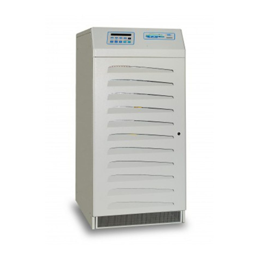
- Page 65 1055 Front view Top view Control, measurement and signalling panel Mimic diagram Electronic cubicle Input/output switch door. Figure 2A: Size 20-60kVA 6-pulse and 20-40kVA 12-pulse without batteries Size 20-40kVA 6-pulse with batteries included IV306E e SP133E Figure 2: Overall View Pag.
- Page 66 1415 Front view Top view Control, measurement and signalling panel Mimic diagram Electronic cubicle Input/output switch door. Figure 2B: Size 80-100kVA 6-pulse and 50-80kVA 12-pulse IV306E e SP133E Figure 2: Overall View Pag. 2 di 6...
- Page 67 Front view Top view Control, measurement and signalling panel Mimic diagram Input/output switch box Electronic cubicle FIGURE 2C: Size 120-160kVA 6-pulse 100-120kVA 12-pulse IV306E e SP133E Figure 2: Overall View Pag. 3 di 6...
- Page 68 Front View Control, measurement and signalling panel Mimic diagram Input/output switch door FIGURE 2D: Size 200-250kVA 6-pulse and 160-250kVA 12-pulse IV306E e SP133E Figure 2: Overall View Pag. 4 di 6...
- Page 69 2000 Front view 1500 1000 Top view Control, measurement and signalling panel Mimic diagram Input/output switch door FIGURE 2E: Size 300-400kVA IV306E e SP133E Figure 2: Overall View Pag. 5 di 6...
- Page 70 2000 Front view 1350 1350 1000 Top view Control, measurement and signalling panel Mimic diagram Input-output switch door FIGURE 2F: Size 500-1000kVA IV306E e SP133E Figure 2: Overall View Pag. 6 di 6...
- Page 71 S1 Mains input switch S2 Output switch S3 By-pass (Not for parallel) S4 Reserve input switch Fb1 Battery fuses Figure 3A Size 20-40kVA 6-pulse and 12-pulse IV306E e SP133E Figure 3: Switches Pag.1 of 7...
- Page 72 S1 Mains input switch S2 Output switch S3 By-pass (Not for parallel) S4 Reserve input switch Figure 3B Size 50-60kVA 6-pulse IV306E e SP133E Figure 3: Switches Pag.2 of 7...
- Page 73 S1 Mains input switch S2 Output switch S3 By-pass (Not for parallel) S4 Reserve input switch Figure 3C Size 80-100kVA 6-pulse and 50-80kVA 12-pulse IV306E e SP133E Figure 3: Switches Pag.3 of 7...
- Page 74 S1 Mains input switch S2 Output switch S3 By-pass (Not for parallel) S4 Reserve input switch Figure 3D Size 120-160kVA 6-pulse and 100-120kVA 12-pulse IV306E e SP133E Figure 3: Switches Pag.4 of 7...
- Page 75 S1 Mains input switch S2 Output switch S3 By-pass (Not for parallel) S4 Reserve input switch Figure 3E Size 200-250kVA 6-pulse and 160-250kVA 12-pulse IV306E e SP133E Figure 3: Switches Pag.5 of 7...
- Page 76 S1 Mains input switch S2 Output switch S3 By-pass (Not for parallel) S4 Reserve input switch Figure 3F: Size 300-400kVA IV306E e SP133E Figure 3: Switches Pag.6 of 7...
- Page 77 S1 Mains input switch S2 Output switch S3 By-pass (Not for parallel) (Built in the inverter frame) S4 Reserve input switch Figure 3G: Size 500-800KVA IV306E e SP133E Figure 3: Switches Pag.7 of 7...
- Page 78 Figure 4A: Size 60-80KVA 12-pulse and 80-100KVA 6-pulse Figure 4B: Different size IV306E e SP133E Figure 4: Signalling Pag.1 of 1...
- Page 79 Figure 5A: Size 60-80KVA 12-pulse and 80-100KVA 6-pulse Figure 5B: Different size IV306E e SP133E Figura 5: Functional Diagram Pag. 1 di 1...
- Page 80 IV306E e SP133E Figure 6: Customer Interface Card Pag. 1 of 1...
- Page 81 BATTERY DISCHARGED-5 9-LOAD ON MAINS 7-UPS ON MAINS OFF-2 6-SHUT-DOWN 9-LOAD ON MAINS 7-UPS ON 5-BATTERY DISCHARGED 2-MAINS OFF 4-COMMON 6-SHUT DOWN IV306E e SP133E Figure 7: DB9 Dry Contacts Pag. 1 of 1...
- Page 82 M1-1 Mains OFF M1-2 M1-3 M1-4 M1-5 Battery discharged M1-6 M1-7 M1-8 UPS ON M1-9 M1-10 M1-11 Load on main M1-12 M2-1 Load on inverter M2-2 M2-3 M2-4 M2-5 Battery alarm M2-6 M2-7 M2-8 Reserve mains OK M2-9 M2-10 M2-11 Recharge M2-12 M3-1...
- Page 83 CONNECTIONS: IN RECT = Mains input IN RES = Reserve input OUT UPS = Out UPS BATT = Battery plug-in connector = Neutral = Phase L1 ( R ) = Phase L2 ( S ) = Phase L3 ( T ) = Battery + = Battery - = Ground connection...
- Page 84 CONNECTIONS: IN RECT = Mains input IN RES = Reserve input OUT UPS = Out UPS BATT = Battery plug-in connector * In the standard configuration, we provide the jumper between the Rectifier and the Reserve input for a single line supply. In case of a double line supply these jumper must be remouved. = Neutral = Phase L1 ( R ) = Phase L2 ( S )
- Page 85 SWITCHES CUBICLE CONNECTIONS S1= Rectifier switch S2= Output switch (Not for parallel) S3= By-pass S4= Reserve switch N= Neutral L1= Phase L1 ( R ) L2= Phase L2 ( S ) L3= Phase L3 ( T ) IN RES= Reserve input IN RECT= Mains input OUT UPS= Out UPS BOTTOM-LEFT CUBICLE CONNECTIONS...
- Page 86 S1= Rectifier switch S2= Output switch S3= By-pass (Not for parallel) S4= Reserve switch N= Neutral L1= Phase L1 ( R ) L2= Phase L2 ( S ) L3= Phase L3 ( T ) IN RES= Reserve input IN RECT= Mains input OUT UPS= Out UPS GND = CONNECTING OF EARTH = Battery +...
- Page 87 S1= Rectifier switch S2= Output switch S3= By-pass (Not for parallel) S4= Reserve switch N= Neutral L1= Phase L1 ( R ) L2= Phase L2 ( S ) L3= Phase L3 ( T ) IN RES= Reserve input IN RECT= Mains input OUT UPS= Out UPS = Battery + = Battery -...
- Page 88 IN RECT OUT UPS IN RES S1= Rectifier switch S2= Output switch S3= By-pass (Not for parallel) S4= Reserve switch N= Neutral L1= Phase L1 ( R ) L2= Phase L2 ( S ) L3= Phase L3 ( T ) IN RES = Reserve input IN RECT...
- Page 89 S1= Rectifier switch S2= Output switch S3= By-pass (Not for parallel) S4= Reserve switch N= Neutral L1= Phase L1 ( R ) L2= Phase L2 ( S ) L3= Phase L3 ( T ) IN RES = Reserve input IN RECT = Mains input OUT UPS = Out UPS...
- Page 90 IN RECT IN RES OUT UPS Neutral Phase L1 ( R ) Phase L2 ( S ) Phase L3 ( T ) IN RES = Reserve input IN RECT = Mains input OUT UPS = Out UPS = Battery + connection = Battery - connection = Ground connection Note: The connection bars are doubled to allow the connection of four wire.
- Page 91 Figure 10A: Size 20-60kVA 6-pulse and 20-40kVA 12-pulse without batteries Size 20-40KVA 6-pulse with batteries included If clearing around the Ups is not sufficient, longer cables must be considered to perform extraordinary maintanance operations.(Castor with brakes are fitted to help moving the Ups).
- Page 92 1000 min 1415 750min Figure 10B: Size 80-100kVA 6-pulse and 50- 80kVA 12-pulse The UPS can be closed at wall; the 200mm dimensions is only for reference. When it is impossible provide for a sufficient gaps from the wall, a suitable length of cables must be provided to remove the UPS in case of extraordinary repairs.
- Page 93 FIGURE 10C: Size 120-160kVA 6-pulse Size 100-120kVA 12-pulse 200mm between UPS and wall must be provided in order to allow the cooling air inlet. When it is impossible provide for a sufficient gaps from the wall, a suitable length of cables must be provided to remove the UPS in case of extraordinary repairs.
- Page 94 10 cm so that air can circulate freely. If system requirements make it necessary, under-floor air intake pipes and/or air exhaust pipes can be used. Contact Siel S.p.A. for customization of panelling and formal and explicit approval of the cooling system project.
- Page 95 10 cm so that air can circulate freely. If system requirements make it necessary, under-floor air intake pipes and/or air exhaust pipes can be used. Contact Siel S.p.A. for customization of panelling and formal and explicit approval of the cooling system project.
- Page 96 10 cm so that air can circulate freely. If system requirements make it necessary, under-floor air intake pipes and/or air exhaust pipes can be used. Contact Siel S.p.A. for customization of panelling and formal and explicit approval of the cooling system project.
- Page 97 When is necessary to design a UPS system able to supply by inverter the load in any situation of maintenance or repairs, please contact the technical department of Siel. IV306E e SP133E Figure 11: Parallel Block Diagram...
- Page 98 UPS1 UPS2 Inverter Control Logic Inverter Control Logic CS221 CS221 SF597 SF597 T1 T2 T3 T4 R1 R2 R3 R4 T1 T2 T3 T4 R1 R2 R3 R4 Static Switch Control Logic Static Switch Control Logic SF643 SF643 T1 R1 T2 R2 T3 R3 T4 R4 T5 R5 T1 R1 T2 R2 T3 R3 T4 R4 T5 R5 IV306E e SP133E Figure 12: Optic Fiber Connection: 2 UPS in Parallel...
- Page 99 UPS1 UPS2 Inverter Control Logic Inverter Control Logic Inverter Control Logic CS221 CS221 CS221 SF597 SF597 SF597 T1 T2 T3 T4 R1 R2 R3 R4 T1 T2 T3 T4 R1 R2 R3 R4 T1 T2 T3 T4 R1 R2 R3 R4 Static Switch Control Logic Static Switch Control Logic Static Switch Control Logic...
Need help?
Do you have a question about the Safepower Evo 20 and is the answer not in the manual?
Questions and answers