
Subscribe to Our Youtube Channel
Related Manuals for Siel SAFEPOWER SPM


Summary of Contents for Siel SAFEPOWER SPM
- Page 1 800-1280kVA UPS INSTALLATION AND USER MANUAL SAFEPOWER SPM KEEP FOR FUTURE REFERENCE for the entire life of the appliance IV374E Rev.03 Installation and user manual Date of issue : 2016-09-06 Page 0 of 63 + FR...
- Page 3 All rights reserved. The information in this document is subject to change without notice. Publish statement Thank you for purchasing this series UPS. This series UPS is an intelligent, three-phase in three-phase out, high frequency online UPS supplied to you by a company with years of designing experiences on UPS. With excellent electrical performance, perfect intelligent monitoring and network functions, smart appearance, complying with EMC and safety standards, The UPS meets the world’s advanced level.
-
Page 4: Table Of Contents
Contents 1.Safety ............................3 1.1 Safety notes ............................3 1.2 Symbols used in this guide ......................3 2.Main Features ........................4 2.1 Summarization ........................... 4 2.2 Functions and Features ........................4 3.Installation ..........................5 3.1 Unpack checking ..........................5 3.2 The appearance of the product ..................... 5 3.3 UPS module appearance ...................... -
Page 5: 1.Safety
1.Safety Important safety instructions – Save these instructions There exists dangerous voltage and high temperature inside the UPS. During the installation, operation and maintenance, please abide the local safety instructions and relative laws, otherwise it will result in personnel injury or equipment damage. Safety instructions in this manual act as a supplementary for the local safety instructions. -
Page 6: 2.Main Features
WARNING! Risk of electric shock CAUTION! Read this information to avoid equipment damage 2.Main Features 2.1 Summarization Our UPS is a kind of three-in- three -out high frequency online UPS. The product is modularized and adopt the N+X redundancy. It can flexibly increase the number of the UPS modules according to the load capacity which is convenient for flexible allocation and gradually investment. -
Page 7: 3.Installation
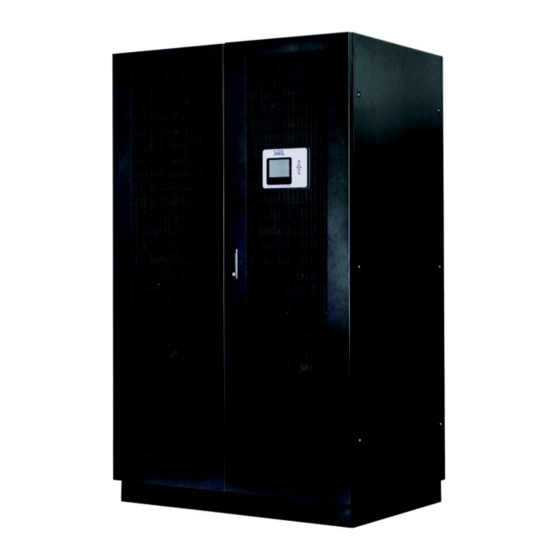
◆ Optimizing distributed convergence for the cabinet ◆ Distributed automatic bypass ◆ Common Battery ◆ Automatic charge current adjustment according to battery capacity connected. ◆ 3-Stage Intelligent charging ◆ Touch-screen Super-large LCD display ◆ Each module with indiviaul LCD display ◆... - Page 8 800 kVA cabinet Front View Front View (No doors) IV374E Rev.03 Installation and user manual Date of issue : 2016-09-06 Page 6 of 63 + FR...
- Page 9 Rear View (internal) Power cabinet Distribution cabinet Power module:1~20 Fuse box : 1~20 Bypass choke module Communication module Mains filter capacitor box Mains filter capacitor breaker I/P switch 10. Lightning arrester 11. Bypass filter capacitor box 12. Bypass filter capacitor breaker 13.
- Page 10 16. Output filter capacitor box 17. Output filter capacitor breaker 18. O/P Switch 19. Mains input phase C copper bar 20. Mains input phase B copper bar 21. Mains input phase A copper bar 22. Bypass input phase C copper bar 23.
- Page 11 1280kVA cabinet Front View Front View (No door) IV374E Rev.03 Installation and user manual Date of issue : 2016-09-06 Page 9 of 63 + FR...
- Page 12 Rear View(internal) 1. Power cabinet 2. Distribution cabinet 3~34: Power module:1~32 35. Communication module 36. I/P Switch 37. Bypass Switch 38. Maintenance switch 39. Maintenance switch cover : Remove cover, UPS transfers to maintenance 40. O/P Switch 41~72. Fuse box : 1~32 73.
- Page 13 80. Input neutral copper 81. Output phase A copper bar 82. Output phase B copper bar 83. Output phase C copper bar 84. Battery positive copper bar 85. Battery negative copper bar 86. Grounding 87. Battery negative copper bar 88. Battery positive copper bar 89.
-
Page 14: Ups Module Appearance
3.3 UPS module appearance Front View Rear View Side View (1) Module left switch screw (2) Module right switch screw (3) Module fixed screw (4) handle (5) LCD display (6) INV fan (7) PFC fan (8) Module output connector slot IV374E Rev.03 Installation and user manual Date of issue : 2016-09-06... -
Page 15: Ups Module Lcd Control Panel
(9) Module input connector slot 3.4 UPS Module LCD control panel LCD control panel introduction (1) LED(from top to bottom: “alarm”, “bypass mode”, “battery mode”, “mains mode”) (2) LCD display (3) scroll button (4) Off button (5) On button 3.5 Installation notes Note: Consider for the convenience of operation and maintenance, the space in front and back of the cabinet should be left at least 100cm and 80cm respectively when installing the cabinet . -
Page 16: External Protective Devices
WARNING! Typical battery performance data are quoted for an operating temperature between 20°C and 25°C. Operating it above this range will reduce the battery life while operation below this range will reduce the battery capacity ◆ Should the equipment not be installed immediately it must be stored in a room so as to protect it against excessive humidity and or heat sources . -
Page 17: Power Cable Connection
(temperature and physical support means) . WARNING! UPON STARTING, PLEASE ENSURE THAT YOU ARE AWARE OF THE LOCATION AND OPERATION OF THE EXTERNAL ISOLATORS WHICH ARE CONNECTED INPUT/BYPASS SUPPLY MAINS DISTRIBUTION PANEL. CHECK THESE SUPPLIES ELECTRICALLY ISOLATED, AND POST ANY NECESSARY WARNING SIGNS TO PREVENT ANY INADVERTENT OPERATION ◆... -
Page 18: Battery Connection
WARNING! If the load equipment is not ready to accept power on the arrival of the commissioning engineer then ensure that the system output cables are safely isolated at their ends Connect the safety earth and any necessary bonding earth cables to the copper earth screw bar located on the bottom of the equipment below the power connections. - Page 19 Note: The BAT+ of the UPS connect poles is connected to the anode (+) of the positive battery, the BAT-N is connected to the cathode (-) of the positive battery and the anode of the negative battery, the BAT- is connected to the cathode of the negative battery.
-
Page 20: Online Ups Modules Replacement
3.10 Online UPS modules Replacement For the UPS, modules must be inserted to make a complete UPS system. The replacement of UPS module is very simple and can be operated online.The control system of the UPS can detect the inserted or removed module(s) automatically. The user may operate easily by following the steps mentioned below. -
Page 21: Ups Multi-Module Installation
until the module starts. UPS Multi-Module Installation 3.11 The basic installation procedure of a parallel system comprising of two or more UPS modules is the same as that of single module system. The following sections introduce the installation procedures specified to the parallel system. 3.11.1 Cabinet installation Connect all the UPSes needed to be put into parallel system as below picture. -
Page 22: Parallel Cable Installation
3.11.2 Parallel cable installation Shielded and double insulated control cables available must be interconnected in a ring configuration between UPS modules as shown below. The parallel control board is mounted on each UPS module. The ring configuration ensures high reliability of the control. 3.12 LBS installation LBS system contains LCD set, cable connections and UPS installation. -
Page 23: Lbs Cable Installation
Parallel ID Internal Module amount Float Volt Revise 0.003 ▼ Master ▲ Parallel Amount Disable Ensure Cancel One UPS set LBS to Slave 520KVA 23-05-2014 On-Line ID:01 08:00 ◄ ► Setting Record Version Command Parallel ID Internal Module amount Float Volt Revise 0.003 ▼... -
Page 24: 4.Operation
MASTER UPS_1 M、N>=1 UPS_2 Input Output UPS_N Load SLAVE UPS_1 UPS_2 Input Output UPS_M 4.Operation 4.1 Operation Modes The UPS is a double-conversion on-line UPS that may operate in the following alternative modes: ◆ Normal mode The rectifier/charger derives power from the AC Mains and supplies DC power to the inverter while floating and boosting charge the battery simultaneously. -
Page 25: Turn On/Off Ups
A manual bypass switch is available to ensure continuity of supply to the critical load when the UPS is out of order or in repair. This manual bypass switch is fitted for all UPS modules and bears for equivalent rated load. ◆... -
Page 26: Test Procedure
◆ Switch ON output switch If the rectifier of the module does not start-up, the bypass LED will light up. When the inverter is on, the UPS will transfer from bypass mode to inverter mode, then the bypass LED is off and the inveter LED is on. No matter the UPS is operated normally or not, the LCD display will indicate current status. -
Page 27: Maintenance Bypass
When battery normal, rectifier starts operation, 30s later, inverter starts and operates and battery LED on CAUTION! Wait f or approximately 30 seconds after you press the black start key 4.2.4 MAINTENANCE BYPASS To supply the load via Mains, you may simply active the internal mechanical bypass switch. CAUTION! The load is not protected by the UPS when the internal mechanical bypass system is active and the power is not conditioned. -
Page 28: Shut Down Procedure
◆ Put on the maintenance switch cover. The rectifier will operate normally after 30 seconds. If the inverter works normally, the system will be transferred from bypass mode to normal mode. 4.2.5 Shut down procedure CAUTION! This procedure should be followed to completely shut down the UPS and the LOAD. -
Page 29: The Display
The UPS cannot be parallel until each single unit is normal. 4.3 The Display 4.3.1 System LCD dispay Overview of the operating panel of the UPS 1) Touch LCD screen :monitoring of all measured parameters, UPS and Battery status and event and alarm logs 2)... - Page 30 ID:01 08:00 1280KVA 23-05-2014 On-Line ◄ ► Output Module Input Batt State ID:01 08:00 ◄ ► Output Module Input Batt State Phase Voltage(v) 220 221 221 Module01 Online Phase Current(A) Module02 Online Frequency(H Module03 Online Active Power(kw) 5.0 5.2 Module04 Online Apparent Power(KVA) 3.7 3.9...
- Page 31 1280KVA 23-05-2014 1280KVA 23-05-2014 On-Line On-Line ID:01 08:00 ID:01 08:00 ◄ ► ◄ ► Setting Record Version Command Setting Record Version Language/English Battery Test Change Password Date Setting 2012-05-23 08:00 Buzzer Set Back-Light Delay 10 min Contrast Default Set Self-Test Date disable Timing of ON/OFF disable...
- Page 32 1280KVA 23-05-2014 1280KVA 23-05-2014 On-Line On-Line ID:01 08:00 ID:01 08:00 ◄ ► ◄ ► Setting Record Version Command Setting Record Version Command SYS Version: V02×10 ▲ ID:01 Record:0001 2013-12-21 15:00:25 LCD Version: 701×02F Status:On Line ▼ Event: On Line Alarm: CODE:CC00-0000 DF00-0000 0000 0000-0000...
- Page 33 1280KVA 23-05-2014 1280KVA 23-05-2014 On-Line On-Line ID:01 08:00 ID:01 08:00 ◄ ► ◄ ► Command Setting Record Version Command Setting Record Version Language/English Date Setting Change Password 2012-01-01 08:00 Date Setting 2008-12-22 08:00:00 Back-Light Delay Back-light Delay 10Min Cancel ▼ 10 ▲ Contrast ←...
- Page 34 1280KVA 23-05-2014 1280KVA 23-05-2014 On-Line On-Line ID:01 08:00 ID:01 08:00 ◄ ► ◄ ► Setting Record Version Setting Record Version Command Command Work Mode Single Work Mode Single Method Normal System Voltage Level 220V System Voltage Level 220V System Frequence Level Bypass Freq.
- Page 35 1280KVA 23-05-2014 1280KVA 23-05-2014 On-Line On-Line ID:01 08:00 ID:01 08:00 ◄ ► ◄ ► Command Setting Record Version Command Setting Record Version Parallel ID Parallel ID Float Volt Revise 0.00 Float Volt Revise 0.00 Parallel Amount Parallel Amount Parallel Amount Float Volt Revise ▼...
- Page 36 1280KVA 23-05-2013 1280KVA 23-05-2014 On-Line On-Line ID:01 08:00 ID:01 08:00 ◄ ► ◄ ► Setting Record Version Setting Record Version Single Battery Volt. Single Battery Capa. Battery Number 0100 Battery Group Max Charge Current Single Battery Capa. 100AH Cancel Boost Upper Limit Volt. 2.31 ▼...
-
Page 37: Ups Module Lcd Display
1280KVA 23-05-2014 On-Line ID:01 08:00 ◄ ► Command Setting Record Version Single Battery Volt. Battery Number Battery Group Single Battery Capa. 100AH Boost Upper Limit Volt. Boost Upper Limit Volt. 2.31 ▼ 2.32 ▲ Float Base Volt. 2.25 Battery Protect Volt. 1.70 Ensure Cancel... - Page 38 Item Interface Description Content Displayed CODE Operational status and mode Input A(Input L1) Voltage & Frequency Input B(Input L2) Voltage & Frequency Input C(Input L3) Voltage & Frequency Bat. + Voltage & Current Bat. - Voltage & Current Output A(Output L1) Voltage &...
- Page 39 2.Phase A(L1) Input/Frequency 3. Phase B(L2) Input/Frequency 4. Phase C(L3) Input/Frequenc 5. Bat +(Positive) IV374E Rev.03 Installation and user manual Date of issue : 2016-09-06 Page 37 of 63 + FR...
- Page 40 6. Bat –(Negative) 7. Phase A(L1) Output Voltage/Frequency 8. Phase B(L2) Output Voltage/Frequency 9.Phase C(L3) Output Voltage/Frequency 10. Phase A(L1) Load Capacity 11. Phase B(L2) Load Capacity IV374E Rev.03 Installation and user manual Date of issue : 2016-09-06 Page 38 of 63 + FR...
- Page 41 12. Phase C(L3) Load Capacity 13.Total Load Capacity 14. Internal temperature and ambient temperature 15. Software version & model 16.Alarm Code IV374E Rev.03 Installation and user manual Date of issue : 2016-09-06 Page 39 of 63 + FR...
- Page 42 If some of above interfaces have battery charging, it will display the charging information at the same time as shown below. Charging Status Boost Floating 3) Pressing “scroll” button, you may circulate all messages from the first one to the last one then returns back to the first one and vice versa.
-
Page 43: Display Messages/Troubleshooting
(10) LED indication (11) Function key (12) LCD port : connected to LCD panel CAUTION! The LEDs mounted on the mimic flow chart represent the various power paths and current UPS operational status. Mains indicator Green Rectifier in Normal Operation Flashing Input mains voltage or frequency out of normal range Green... - Page 44 Module Display messages Operational Status and Mode(s) item Content Displayed alarm Bps output Bat. output Mains output Initialized Extinguish Extinguish Extinguish Extinguish Standby Mode Extinguish Extinguish Extinguish No Output Extinguish Extinguish Extinguish Bypass Mode Extinguish Light Extinguish Utility Mode Extinguish Extinguish Light Battery Mode...
- Page 45 Inverter Over temperature Twice per second Fault LED lit No neutral Twice per second Fault LED lit Battery reverse Twice per second Fault LED lit Cable connection error Twice per second Fault LED lit CAN comm. Fault Twice per second Fault LED lit Parallel load sharing fault Twice per second...
- Page 46 Int. Input switch opened The internal input switch is opened manually. Rectifier deactivated The rectifier has been deactivated. Rectifier activated The rectifier has been activated. When the input voltage is at 208V~305V, the output of the UPS will not be interrupted, but it will be at current limit, for Rectifier current limit example, to reduce charge current.
- Page 47 Module connected Module is connected Module removed Module is removed Cabinet Alarm Information Display message Meaning Rectifier detected faulty. Rectifier and inverter and charger Rectifier Fault shut down. The temperature of heatsink is too high to keep the rectifier Rectifier Over Temperature running.
- Page 48 Inverter Thyristor short SCR at the inverter side is short-circuited fault Inverter Thyristor broken fault SCR at the inverter side is open-circuited SCR at the bypass side is short-circuited Bypass Thyristor short fault Bypass Thyristor broken fault SCR at the bypass side is open-circuited CAN comm.
-
Page 49: Options
Model set wrong Model setting of the UPS is incorrect. 4.5 Options SNMP card CAUTION! For network management configuration and use, refer to the separate user manual - Network Management Card with Environmental Monitor - shipped with the CARD Network Management Card replacement (internal SNMP) ◆... -
Page 50: Appendix 1 Specifications
Appendix 1 Specifications Model 800k 1280k Cabinet capacity 800kVA 1280kVA Module capacity 40kVA 40kVA Max. module number Phase 3 Phase 4 Wires and Ground Rated Voltage 380/400/415Vac Voltage Range 208~478Vac Frequency Range 40Hz-70Hz ≥0.99 Power Factor Input ≤3%(100% nonlinear load) Current THDi Max.voltage: 220V:+25%(optional +10%,+15%,+20%);... - Page 51 Load≤110%: last 60min, ≤125%: last 10min, ≤150%: last Bat. Mode 1min, ≥150% shut down UPS. Input 160A Fuse Box Battery 200A Short Circuit (module) 180A peak Line Mode: Switch to Bypass; Overheat Battery Mode: Shut down UPS immediately Battery Low Alarm and Switch off Self-diagnostics Upon Power On and Software Control...
-
Page 52: Appendix 2 Ups Message Table
Appendix 2 UPS message table 1. The Inner Code is applied to this Series. The following format block is Inner Code display on LCD: AAAA–AAAA BBBB-BBBB EEFF CCCC-CCCC DDDD-DDDD 2. The part of Inner Code means AAAA-AAAA(Rectifier State): Axxx-xxxx A B C D E F Int. Input Switch closed C D E F Rectifier Activated E F Emergency Power off F Rectifier current Limt... - Page 53 xxxx-xxxA A B C D E F C D E F BBBB-BBBB(Inverter State): Bxxx-xxxx A B C D E F Int. bypass Switch Closed C D E F Int. output Switch Closed E F Manu-Bypass Switch Closed F Ext. bypass Switch Closed xBxx-xxxx A B C D E F Ext.
- Page 54 E F Parallel in Bypass F LBS Activated xxxx-xxxB A B C D E F INV standby C D E F CCCC-CCCC(Rectifier Alarm): Cxxx-xxxx 8 9 A B C D E F Rectifier fault 4 5 6 7 C D E F Rectifier over temperature E F Inverter over temperature F Rectifier over current xCxx-xxxx...
- Page 55 xxxx-xxxC A B C D E F C D E F DDDD-DDDD(Inverter Alarm): Dxxx-xxxx A B C D E F Inverter fault C D E F Inv. IGBT bridge shorted E F Inverter Thyristor short F Inverter Thyristor broken xDxx-xxxx A B C D E F Bypass Thyristor short C D E F Bypass Thyristor broken E F CAN comm.
- Page 56 8 9 A B C D E F generator Connect 4 5 6 7 C D E F ShutDown Due To Batt. Low E F Time to turn on F Time to turn off 8 9 A B C D E F timing self test start 4 5 6 7 C D E F Surge protection active signal, from monitoring board IO...
-
Page 57: Appendix 3 Problems And Solution
Appendix 3 Problems and Solution In case the UPS can not work normally, it might be wrong in installation, wiring or operation. Please check these aspects first. If all these aspects are checked without any problem, please consult with local agent right away and provide below informations. (1)... - Page 58 Switch on the battery switch. If batteries are damaged, need to Battery switch does not switch replace whole group batteries, Battery on, or batteries are damaged, Connect battery cables flashing but battery reversely charge voltage connected. correctly; and current battery number and capacity Go to LCD setting of the battery are not set correctly.
-
Page 59: Appendix 4 Rs232 Communication Port Definition
Appendix 4 RS232 communication port definition Definition of Male port Connection between PC RS232 port and UPS RS232 port PC RS232 port UPS RS232 port , PC Pin 2 Pin 2 send receive , UPS Pin 3 Pin 3 send receive Pin 5 Pin 5... -
Page 60: Appendix 5 Rs485 Communication Port Definition
Appendix 5 RS485 communication port definition Definition of port Connection between the Device’s RS485 port and UPS RS485 port. device(RJ45) UPS(RJ45) Description 485+ “A” Pin 1/5 Pin 1/5 485 - “B” Pin 2/4 Pin 2/4 Available function of RS485 ◆ Monitor UPS power status. ◆... -
Page 61: Appendix 6 Bat_T Communication Port Definition
Appendix 6 BAT_T communication port definition Definition of port Connection between the BAT_T box port and UPS2’s BAT_T port. (RC77002) Temperature sensor(RJ45) UPS2 BAT_T(RJ45) Description Pin 1/5 Pin 1/5 Pin 2/4 Pin 2/4 Pin 7 Pin 7 Pin 8 Pin 8 Connection between the BAT_T box port and UPS2’s BAT_T port. -
Page 62: Appendix 7 Drycontact Port Definition
Appendix 7 Drycontact port definition Definition of port Drycontact(RJ45) Description Pin 1/5 DRY_BP_S Pin 2/4 DRY_BP_O Pin 7 DRY_GENER Pin 8 IV374E Rev.03 Installation and user manual Date of issue : 2016-09-06 Page 60 of 63 + FR... -
Page 63: Appendix 8 Repo Instruction
Appendix 8 REPO instruction Definition of port Connection diagram: Connection between the button and UPS REPO port. Button UPS REPO Description Pin 1 Pin 1 Pin 2 Pin 2 ◆ In addition to the local EPO push button on the front panel of the UPS (that stops operation of that module when pressed for more than 3 second), the UPS also supports a remote emergency stop (REPO). -
Page 64: Appendix 9 Lbs Communication Port Definition
Appendix 9 LBS communication port definition Definition of port Connection between the UPS1’s LBS1 port and UPS2’s LBS2 port. UPS1 LBS1(RJ45) UPS2 LBS2(RJ45) Description Pin 1/5 Pin 1/5 LBS_BPSIDE_BC Pin 2/4 Pin 2/4 LBS_TRACE_BC Pin 8 Pin 8 Available function of LBS ◆The output power of two or more UPS in non-parallel system should be synchronized with each other. - Page 65 IV374E Rev.03 Installation and user manual Date of issue: 2016-09-6 Pag. 63di 63+ FR...
Need help?
Do you have a question about the SAFEPOWER SPM and is the answer not in the manual?
Questions and answers