Honeywell PRO4200 Installation Manual
Two reader module
Hide thumbs
Also See for PRO4200:
- Installation manual (25 pages) ,
- Installation manual (24 pages) ,
- Installation manual (36 pages)

Subscribe to Our Youtube Channel
Related Manuals for Honeywell PRO4200


Summary of Contents for Honeywell PRO4200
- Page 1 PRO4200 Two Reader Module (PRO42R2) Installation Guide 800-25698V1 September 2020 © 2020Honeywell International, Inc. All rights reserved...
- Page 2 All product and brand names are the service marks, trademarks, registered trademarks, or registered service marks of their respective owners. Printed in the United States of America. Honeywell reserves the right to change any information in this document at any time without prior notice.
-
Page 3: Table Of Contents
..........................Wiring Diagram for Connectors TB1,TB7-9 ..18 ............... 2-Reader Input Module Programming Guide ..25 ............................. PRO4200 Two-Reader Module User Guide, Document 800-25698V1... - Page 4 (This page is left blank intentionally for double-sided printing.) www.honeywell.com...
-
Page 5: Notices
DO NOT ACCEPT VERBAL APPROVALS, BECAUSE THEY ARE NOT VALID. Honeywell never recommends using the PRO4200 or related products for use as a primary warning or monitoring system. Primary warning or monitoring systems should always meet local fire and safety code requirements. The installer must also test the system on a regular basis by instructing the end user in appropriate daily testing procedures. -
Page 6: Disclaimer
Customer harmless for any costs or damages including reasonable attorneys' fees which Customer may be required to pay as a result of the defective Product or the negligence of Honeywell, its agents, or its employees. -
Page 7: Compliance
For any additional information regarding the compliance of this product to any EU-specific requirements, please contact: Honeywell Security & Communications Honeywell Security - Quality Assurance Dept., Newhouse Industrial Estate Motherwell Lanarkshire ML1 5SB Scotland United Kingdom Tel: +44(0) 1698 738200 Email: UK64Sales@Honeywell.com... - Page 8 Notices Unpacking Procedure • If shipping caused damage to the unit, a claim must be filed with the commercial carrier. • If any other defect is apparent, call for a return authorization. viii www.honeywell.com...
-
Page 9: Shipping Instructions
All Products sold or licensed by Honeywell include a warranty registration card which must be completed and returned to Honeywell by or on behalf of the end user in order for Honeywell to provide warranty service, repair, credit or exchange. All warranty... -
Page 10: Confidentiality
Confidentiality All software, drawings, diagrams, specifications, catalogs, literature, manuals and other materials furnished by Honeywell relating to the design, use and service of the Products shall remain confidential and shall constitute proprietary rights of Honeywell and Customer agrees to treat such information as confidential. Customer shall acquire no rights in the design of the Products or the related materials except to use such information solely for the purpose of and only during the time it sells the Products. -
Page 11: Installing The Pro4200 Two Reader Module
Module Description The PRO4200 Two-Reader Module provides support for up to two access control doors by providing connections for Wiegand or Clock/Data type readers, supervised inputs, and relay outputs. You can either mount the board in a rack or open and flat. If you rack-mount the board, only one edge is accessible for wiring;... -
Page 12: Specification
Installing the PRO4200 Two Reader Module Specification Specification The Two-Reader Module is for use in low voltage, class 2 circuits only. Primary power 12VDC + 10% 650mA maximum with 5V readers, 300 mA max. excluding readers Relay contacts • Relays 0 through 1 outputs, Form-C, 5A @ 30VDC, resistive •... -
Page 13: Set Up
Installing the PRO4200 Two Reader Module Set Up Set Up Table 1: PRO4200 IN Module Jumper Setting Jumper Setting Default Selected Port 1 RS-485 EOL terminator is not active Port 1 RS-485 EOL terminator is active Position 5 Reader 1 Power terminals... - Page 14 Installing the PRO4200 Two Reader Module Set Up Selection ADDRESS 16 ADDRESS 17 ADDRESS 18 ADDRESS 19 ADDRESS 20 ADDRESS 21 ADDRESS 22 ADDRESS 23 ADDRESS 24 ADDRESS 25 ADDRESS 26 ADDRESS 27 ADDRESS 28 ADDRESS 29 ADDRESS 30 ADDRESS 31...
-
Page 15: Led Operation
LED becomes ON also.The LED remains ON for as long as the relay is energized. The assignment for each relay status LED is shown in the following table: .The following table lists the LEDs D1 through D4. Table 3: Additional PRO4200 Two Reader Module LEDs LED number Description... -
Page 16: Power
Installing the PRO4200 Two Reader Module Power Table 3: Additional PRO4200 Two Reader Module LEDs LED number Description Input1 Input 2 Input 3 Input 4 Input 5 Input 6 Input 7 Tampert Power Relay 0 status Relay 3 sttatus Relay 2 status... -
Page 17: Wiring
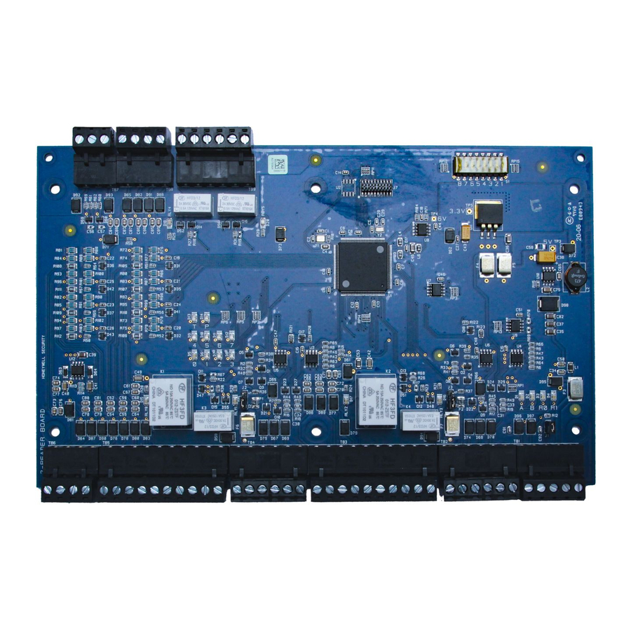
4. Use 24 AWG low capacitance, twisted-pair, shielded cable (Honeywell 3328 or equivalent). Wiring This section presents information on reader wiring, input wiring, and control output wiring. The following figure shows the PRO4200 board and identifies its terminal block pin assignments. PRO4200 Two-reader module User Guide, Document 800-25698V1... -
Page 18: Wiring Diagram For Connectors Tb1,Tb7-9
Note: See LED Operation on page 16 for descriptions of LEDs D1-D20. Reader, Input, and Output addresses on the PRO4200 panel are labeled starting Note: with address 0. This translates to address 1 in the WIN-PAK per the example below:... - Page 19 Input on supervised F/2F readers may be unsupervised or supervised (supervised shown). Reader Wiring The following Honeywell reader module numbers have been approved by UL for use with the PRO4200: OM40BHONA, OM55BHONA, OP10HONE, OP30HONE, PRO4200 Two-reader module User Guide, Document 800-25698V1...
- Page 20 Installing the PRO4200 Two Reader Module Wiring Diagram for Connectors TB1,TB7-9 OP40HONE, OP90HONE, OT30HONA, OT31HONA, OT35HONA, and OT36HONA. Each reader port supports a reader with TTL interface. Power to the reader is selectable as 5VDC or 12VDC (pass-through). This selection is done by setting the jumpers J2 for reader 1 and J3 for reader 1.
- Page 21 To minimize premature contact failure and to increase system reliability, a contact protection circuit is highly recommended. The following two circuits are suggested. Locate the protection circuit as close to the load as possible PRO4200 Two-reader module User Guide, Document 800-25698V1...
- Page 22 Mounting Options This board can be mounted on-edge in the rack-mount enclosure provided by Honeywell or it can be mounted flat against any surface using standoffs under the mounting holes provided in each of the four corners of this board.
- Page 23 8. Recheck wiring for correct connections and continuity. 9. When all boards have been installed, connect the power supply cord for proper 10.connections and power. 11.Set up the panel controls using the host software. PRO4200 Two-reader module User Guide, Document 800-25698V1...
- Page 24 Installing the PRO4200 Two Reader Module Wiring Diagram for Connectors TB1,TB7-9 (This page is left blank intentionally for double-sided printing.) www.honeywell.com...
-
Page 25: 2-Reader Input Module Programming Guide
Door 1 Input / Output Connected Cable # Cable Destination Conductor Color Input 0 Pin #1 Input 0 Com Pin #2 Input 1 Pin #3 Input 1 Com Pin #4 Relay 0 No Pin #5 PRO4200 Two-reader module User Guide, Document 800-25698V1... - Page 26 Cable Destination Conductor Color DC Out ( + ) Pin #1 Red LED Pin #2 Beeper Ctrl Pin #3 Data - 1 Pin #4 Data - 0 Pin #5 Common Pin #6 Reader 1 is Reader 2 in WIN-PAK Note: www.honeywell.com...
- Page 27 Cable Destination Conductor Color Relay 4 NC Pin #1 Relay 4 Com Pin #2 Relay 4 NO Pin #3 Relay 5 NC Pin #4 Relay 5 Com Pin #5 Relay 5 NO Pin #6 PRO4200 Two-reader module User Guide, Document 800-25698V1...
- Page 28 2-Reader Input Module Programming Guide (This page is left blank intentionally for double-sided printing.) www.honeywell.com...
- Page 29 For more information: www.honeywellaccess.com Discover | Customer Portal Self-Service Product Support and Learning Management System https://honeywelldiscovertraining.com/login/discover/default.asp YouTube | Honeywell Help and Support https://www.youtube.com/channel/UCBEL6ouNV_LN5lEpYRujMTg/featured Honeywell Access Systems 135 W. Forest Hill Avenue Oak Creek, WI 53154 United States 800-323-4576 414-766-1798 Fax www.honeywellaccess.com...
Need help?
Do you have a question about the PRO4200 and is the answer not in the manual?
Questions and answers