Table of Contents
Advertisement
Burner control unit PFU 780
Technical Information · GB
6 Edition 02.12l
• For pilot and main burners of unlimited capacity in
thermoprocessing equipment pursuant to EN 746-2
• Separate flame control for pilot burner and main burner by UV,
ionisation or a further option of using the furnace chamber
temperature
• Display of the program status, unit parameters and flame signal;
Manual mode for burner adjustment and for diagnostic purposes
Industrial & Commercial Thermal
AGA
Advertisement
Table of Contents

Related Manuals for Honeywell Krom Schroder PFU 780


Summary of Contents for Honeywell Krom Schroder PFU 780
-
Page 1: Burner Control Unit Pfu 780
Industrial & Commercial Thermal Burner control unit PFU 780 Technical Information · GB 6 Edition 02.12l • For pilot and main burners of unlimited capacity in thermoprocessing equipment pursuant to EN 746-2 • Separate flame control for pilot burner and main burner by UV, ionisation or a further option of using the furnace chamber temperature • Display of the program status, unit parameters and flame signal;... -
Page 2: Table Of Contents
Table of contents Burner control unit PFU 780 . . . . . . . . . . . . . . . . . . . . . . . . . 1 4.5.1 Safety time on start-up t . - Page 3 6.2.2 Star electrodes ........50 8.6 Socket connectors .
-
Page 4: Application
Application Module subrack BGT for instance serves to accom- modate several function units. It is provided with a backplane with screw terminals for simple, reliable wiring. 1 Application the burner always ignites in a safe condition after it has been restarted. The burner control units PFU 780 control, ignite and The burner control unit is used for burners with me- monitor gas burners for intermittent or continuous op-... - Page 5 Application If the local requirements on the burner control units change, the PC software BCSoft can be adjusted to the unit parameters of the application by using the optical interface. To support service personnel, BCSoft offers a conveni- ent visualisation system of the input and output signals and the error history.
-
Page 6: Examples Of Application
Application 1 .1 Examples of application 1 .1 .1 Stage-controlled main burner with alternating pilot burner Control: Main burner ON/OFF. L1, N, PE The main burner can be started with reduced capacity after the operat- ing signal from the pilot burner has been detected. -
Page 7: Stage-Controlled Main Burner With Permanent
Application 1 .1 .2 Stage-controlled main burner with permanent pilot burner Control: Main burner ON/OFF. The main burner can be started with L1, N, PE reduced capacity after the operat- ing signal from the pilot burner has been detected. Pilot and main burn- ers can be operated simultaneously. -
Page 8: Modulating-Controlled Burner
Application 1 .1 .3 Modulating-controlled burner Control: Main burner continuous The butterfly valve for air BV is moved to ignition position in order L1, N, PE to start the main burner. The main burner can be started at low-fire rate after the operating signal from the pilot burner has been detected. -
Page 9: Pfu 780..D
Application 1 .1 .4 PFU 780 . .D: High temperature equipment The flame is controlled indirectly on the basis of the temperature. During the start-up process, as long as the wall temperature is below auto igni- tion temperature the flame must be controlled by conventional meth- ods. -
Page 10: Certification
Certification 2 Certification AGA approved Certified pursuant to SIL Australian Gas Association, Approval No.: 5597 www.aga.asn.au/product_directory For systems up to SIL 3 pursuant to EN 61508 Pursuant to EN ISO 13849-1:2006, Table 4, the PFU can be used up to PL e. EC type-tested and certified pursuant to –... -
Page 11: Function
Function 3 Function PFU 780 L1 (L1) 3 .1 Connection diagram For cable selection and wiring, see page 50 (Project planning information). 3 .1 .1 PFU 780 For the explanation of symbols, see page 67 (Legend). N (L2) 230 V ϑ1 µC 24 V... -
Page 12: Pfu 780
Function 3 .1 .2 PFU 780 . .K2 PFU 780..K2 As a replacement unit for burner control unit PFU 798. L1 (L1) For the explanation of symbols, see page 67 (Legend). N (L2) 230 V ϑ1 µC 24 V ϑ2 PFU 780 ·... -
Page 13: Pfu 780 Program Sequence
Function 3 .2 PFU 780 program sequence PFU 780 Switch on PFU 780 If the air valve control is used, Normal start-up the unit offers the following If an “old” fault is still being sig- In the event of fault signal: additional functions: nalled after switching on, it will be Reset... - Page 14 or fault lock-out Function The PFU coordinates the correct program run for the pilot and main The air valve can be set to open Flame proving period t burners. The main burner can be running (P23) together with V1 (display started via the signal input “Start- via parameter 30.
- Page 15 or fault lock-out Function Behaviour of the pilot burner in the event of flame failure during Flame proving period The air valve can be set to open running (P25) operation with V2 or to be activated ex- If the flame fails during operation, ternally (display ) via param- In the event of flame failure:...
-
Page 16: Program Status And Fault Messages
Function 3 .3 Program status and fault messages The burner control unit can be reset using the Reset button or the remote reset. During operation, the 7-segment display shows the pro- gram status. In the event of a fault, the PFU halts the program run, the display blinks and it then displays the cause of the fault. - Page 17 Function Program status DISPLAY Fault message (blinking*) Permanent reset Time between two start-ups is too short In Manual mode, two dots will blink on the display in program status 01 – 08. ** Optionally available. PFU 780 · Edition 02.12l...
-
Page 18: Parameters
Parameters 4 Parameters Factory default Description Parameter Value range Adjustable* setting Flame signal, pilot burner 0 – 30 µA Flame signal, main burner 0 – 30 µA Program status when the most recent fault occurred x0 – x8 Switch-off threshold, pilot burner 1 – 20 µA 1 µA ... -
Page 19: Scanning The Parameters
Parameters Factory default Description Parameter Value range Adjustable* setting Manual mode limited to 5 minutes 0; 1 UVS check (1 x in 24 hours) 0; 1 Low fire over run time 0; 5; 15; 25 s Purge 0;... -
Page 20: Flame Control
Parameters 4 .2 Flame control 4 .2 .4 Switch-off threshold of the flame amplifier Parameter 04, pilot burner switch-off threshold 4 .2 .1 Flame signal, pilot burner Parameter 05, main burner switch-off threshold Parameter 01 The sensitivity at which the burner control unit still de- Flame signal of the pilot burner, display in A, measur- μ... -
Page 21: High Temperature Operation With Pfu
Parameters 4 .2 .5 High temperature operation with PFU . .D perature monitor with twin thermocouple (DIN 3440). Parameter 33 Sensor discontinuity, sensor short-circuit, failure of a Operation of firing systems at temperatures above component or mains failure must set the installation to a safe state. - Page 22 Parameters The PFU then responds, depending on setting: Parameter 33 = 2 Parameter 33 = 1 2c–4c 2c–4c 6a–6e 2e–4e 6a–6e 2a–4a 2e–4e 2a–4a When High temperature mode is ended, the PFU If the flame fails during high temperature operation, the switches off the burner and restarts with flame simu- ready contact opens for the duration of the flame fail- lation check (recommended in the case of UV control...
- Page 23 Parameters Parameter 33 = 3 Fault, main burner 2c–4c 2c–4c 6a–6e 6a–6e 2e–4e 2e–4e When High temperature mode is ended, the burner re- Parameter 33 = 4 mains in operation and the PFU performs flame control again (recommended in the case of ionisation control or UV control with UVD).
-
Page 24: Uvs Check
Parameters 4 .2 .6 UVS check Parameter 35 An automatic restart of the burner control unit can be activated every 24 hours via this parameter. The time starts each time the start-up signal (ϑ) is applied. Parameter 35 = 0: Unlimited burner operation. Parameter 35 = 1: An automatic restart is activated once every 24 hours. -
Page 25: Pilot And Main Burner Monitoring
Parameters 4 .3 Pilot and main burner monitoring Three different operating modes are possible: Permanent pilot burner Burner control unit PFU 780 for pilot and main burner combination of unlimited capacity. 02–04 06–08 06–08 ϑ1 Pilot burner: single-stage-controlled. ϑ2 Main burner: modulating or stage-controlled. The burner control unit PFU 780 has separate start-up signal inputs for the pilot burner (terminal 10e) and the For applications which require a high system availabil-... - Page 26 Parameters Interrupted pilot burner 02–04 06–08 02–04 06–08 The pilot burner is switched off during the main burner safety time t . This type of flame control is required if no distinction can be made between the flame signals of the pilot and main burners (e.g. if both burners can be monitored with a single UV sensor).
-
Page 27: Permanent Pilot Burner
Parameters 4 .3 .1 Permanent pilot burner Parameter 16 = 1 Operating mode: Permanent pilot burner In the “Permanent pilot burner” operating mode, the pi- lot burner remains in operation until its start-up signal drops. 2c–4c If this parameter is activated (P16 = 1), both flames are controlled independently in the case of pilot and main 6a–6e burner monitoring. -
Page 28: Interrupted Pilot Burner
Parameters 4 .3 .2 Interrupted pilot burner Parameter 16 = 0 Operating mode: Interrupted pilot burner If parameter 16 = 0, the pilot burner is switched off once the safety time t has elapsed. In this setting, the flame signal can be connected to terminals 18a or 26a. 2c–4c The pilot burner is switched off after the main burner safety time t... -
Page 29: Behaviour In Start-Up Position/Standby
Parameters 4 .4 Behaviour in start-up position/standby The burner must have been switched off for at least 4 s before start-up in order for the flame simulation check 4 .4 .1 Flame simulation check in start-up position/ to be conducted correctly. standby Flame simulation check depending on parameter 16 Parameter 15... -
Page 30: Minimum Burner Pause Time T Bp
Parameters 4 .4 .2 Minimum burner pause time t The time should be set such that the system can be Parameter 21 moved to ignition position, i.e. butterfly valves can be Programmable time between 0 and 250 s. closed and, possibly, gas can be flared off, before a re- start occurs. -
Page 31: Behaviour During Start-Up
Parameters 4 .5 Behaviour during start-up Main burner Parameter 24 4 .5 .1 Safety time on start-up t Pilot burner Parameter 22 2c–4c 6a–6e 2e–4e 2c–4c 2e–4e Safety time on start-up t for the main burner. Safety time on start-up t for the pilot burner. -
Page 32: Flame Proving Period T
Parameters 4 .5 .2 Flame proving period t 4 .5 .3 Minimum combustion time t Parameter 20 Pilot burner Parameter 23 2c–4c 6a–6e 2c–4c 2e–4e 2e–4e Programmable time to maximum 25 s during which the main burner remains in operation. In the case of brief Main burner activation of the start-up signal input (ϑ2) (e.g. -
Page 33: Burner Start-Up Attempts
Parameters 4 .5 .4 Burner start-up attempts If no flame forms during start-up, a fault lock-out is performed after expiry of time t . The display blinks Pilot burner and shows the cause of the fault. Parameter 10 This indicates the number of possible start-up attempts 2 or 3 start-up attempts of the burner. - Page 34 Parameters Main burner If no flame forms during the start-up of the main burner, Parameter 11 a fault lock-out is performed after expiry of time t This indicates the number of possible start-up attempts The display blinks and shows the cause of the fault. of the main burner.
-
Page 35: Behaviour During Operation
Parameters 4 .6 Behaviour during operation Immediate fault lock-out following flame failure Parameter 12 = 0: 4 .6 .1 Safety time during operation t for pilot and main Pilot burner fault lock-out. burners Parameter 14 This indicates the safety time during operation t for valves V1 and V2. - Page 36 Parameters Restart following flame failure Parameter 12 = 1: Restart following flame failure. 2c–4c >2 s 2e–4e If the PFU detects a flame failure after a minimum op- erating time of 2 s, the valves are closed and the opera- tion signalling contact is opened within time t The burner control unit now attempts to restart the burner once.
-
Page 37: Fault Lock-Out Or Restart, Main Burner
Parameters 4 .6 .3 Fault lock-out or restart, main burner After a fault lock-out, the burner control unit can be This parameter determines whether the PFU starts a reset, either with the button on the front panel or using one-off restart or performs an immediate fault lock-out an external button. - Page 38 Parameters Restart following flame failure The precondition for a restart is that activation of the Parameter 13 = 1: restart allows the burner to restart as intended (in all Restart following flame failure. operating phases). In this case, it must be ensured that the program sequence started by the PFU matches the application.
-
Page 39: Air Valve Control Pfu
Parameters 4 . 7 Air valve control PFU . .L 4 . 7 .1 Purge Parameter 42 = 0: The air valve is closed when voltage is Parameter 30, Behaviour of the air valve during opera- applied to terminal 30e. tion Parameter 42 = 1: The air valve is opened when voltage Parameter 31, Behaviour of the air valve during start-up... -
Page 40: (Not During Start-Up)
Parameters 4 . 7 .4 Air valve opens in the case of external activation (not Parameter 30 = 0: during start-up) The air valve opens if it is activated externally by input 30e. Parameter 31 = 0: 00 A000 A0 The air valve remains closed during start-up even if it is activated externally. -
Page 41: Air Valve Opens In The Case Of External Activation
Parameters 4 . 7 .5 Air valve opens in the case of external activation Parameter 30 = 0: (even during start-up) The air valve opens if it is activated externally via input 10a. Parameter 31 = 1: 00 A0 00 A0 The air valve can be activated even during start-up. -
Page 42: Air Valve Opens With Valve V2
Parameters 4 . 7 .6 Air valve opens with valve V2 Parameter 30 = 2: The air valve opens simultaneously with valve V2. 00 A0 00 Application: Single-stage-controlled main burner is switched ON/ OFF via the ϑ input. 2c–4c The air valve can be activated externally via input 10a for cooling the burner in the start-up position/standby. -
Page 43: Air Valve Opens With Operating Signal
Parameters 4 . 7 . 7 Air valve opens with operating signal Parameter 30 = 3: The air valve opens simultaneously with the operating signal. Application: Two-stage-controlled main burner is switched ON/OFF via the ϑ input. 2c–4c The air valve can be activated externally via input 10a for cooling the burner in the start-up position/standby. -
Page 44: Low Fire Over Run Time T
Parameters 4 . 7 .8 Low fire over run time t after a normal shut-down Parameter 36 Settings: 0; 3; 5; 10; 15; 25 or 60 (low fire over run time in seconds) This parameter is applicable to systems with a pneu- matic link between gas and air and On/Off control. -
Page 45: Lock-Out
Parameters 4 . 7 .9 Behaviour of the air valve in the event of a fault lock- Parameter 32: This determines whether the air valve can be activated in the case of a fault lock-out. Parameter 32 = 0: The air valve is closed in the event of a fault. -
Page 46: Manual Operation
Parameters 4 .8 Manual operation 4 .8 .1 Manual mode limited to 5 minutes Parameter 34: For convenient setting of the burner or analysing faults. Parameter 34 determines when Manual mode is termi- The parameter display is not available in Manual mode. nated. -
Page 47: Password
Parameters 4 .9 Password Parameter 50: (Four-digit) password saved to protect parameter settings. To prevent unauthorised changes to param- eter settings, a password is stored in parameter 50. Changes to parameter settings can only be made once this number has been entered. The password can be changed using BCSoft. -
Page 48: Selection
Selection 5 Selection 5 .1 Calculating the safety time t PFU 780 · Edition 02.12l... -
Page 49: Selection Table
Selection 5 .2 Selection table 5 .2 .1 Type code Code Description Type Air valve control PFU 780 Mains voltage 220 – 240 V~, -15/+10 %, 50/60 Hz If “none”, this specifi cation is omitted. 110 – 120 V~, -15/+10 %, 50/60 Hz ... -
Page 50: Project Planning Information
Project planning information 6 Project planning information 6 .1 .3 UV-Leitung Cable length: max. 100 m. Avoid external electrical 6 .1 Cable selection interference. Install as far as possible from mains and Use mains cable suitable for the type of operation and ignition cables and interference from electro-magnetic sources. -
Page 51: Minimum Combustion Time
Project planning information 6 .3 Minimum combustion time haviour of the main burner. The minimum combustion time for the pilot burner is limited to the safety time on Even if the start-up signal (ϑ) is applied only briefly, the start-up (t time set under parameter 20 elapses before the burner Background: The pilot burner is only used in single- control unit shuts down the burner or signals a fault. -
Page 52: Emergency Stop
Project planning information 6 .5 Emergency stop can only be acknowledged with the Reset/Information button on the unit. 6 .5 .1 In the event of fire or electric shock The burner malfunction must be remedied. The mal- If there is a risk of fire, electric shock or similar, inputs function can not be remedied by changing the method L1, N and 26e (safety interlocks) of the PFU should be of activation. -
Page 53: Fault Message
Project planning information 6 . 7 Fault message 6 .10 .1 UVS sensor wiring Connect the UVS sensor directly to the PFU. Operating The fault signalling contact opens, as soon as the mains the sensor with incorrect polarity or voltage can lead to voltage fails. -
Page 54: Furnace Control
Project planning information 6 .12 Furnace control ternal switch per unit or group only, in accordance with Standard “EN 50156”. Switch on the system to start up the furnace, then release the burner start via the safety interlocks and 6 .15 Changing parameters afterwards start the burner control so that the burner In certain cases, it may be necessary to change the de- control unit may monitor the burners as intended. -
Page 55: Flame Control
Flame control 7 Flame control The burner control unit PFU..U is prepared for UV sensor UVD 1. This enables continuous operation. For further 7 .1 With ionisation sensor information, see Technical Information Bulletin UVD. The PFU generates an alternating voltage (230 V AC) 7 .3 Via the temperature in high temperature between the sensing electrode and burner earth. -
Page 56: Accessories
Accessories 8 Accessories 8 .4 “Changed parameters” stickers 8 .1 High-voltage cable D-49018 Osnabrück, Germany FZLSi 1/7 up to 180°C, Order No.: 04250410. Achtung, geänderte Parameter! Die Angaben auf dem Typenschild FZLK 1/7 up to 80°C, Order No.: 04250409. gelten nicht mehr in vollem Umfang. Aktuelle Parameter direkt auslesen. -
Page 57: Radio Interference Suppressed Electrode
Accessories 8 .5 Radio interference suppressed electrode Module subrack BGT SM-8/1/1 for MPT 700, PFU 780 adapters comprising: Plug cap, 4 mm, interference-suppressed, module subrack, printed-circuit board with rear ter- Order No. 04115308. minal strip, function-tested, standard documentation, Straight adapter, 6 mm, interference-suppressed, guide rails, without partial front plates, screw terminals Order No. -
Page 58: Power Supply Pfp 700
Accessories 8 .8 Power supply PFP 700 For supplying the control inputs of burner control unit PFU or for supplying the auxiliary voltage to relay module PFR 704. Operating status display on the front plate. PFP switches off in the event of an output over- load. -
Page 59: Relay Module Pfr 704
Accessories 8 .9 Relay module PFR 704 For contact multiplication, e.g. if several air valves are activated via a single control signal for pre-purge, or for heating/cooling switchover when using an MPT. Switching status display on the front plate. Input voltage: 110/120 V AC, -15/+10%, 50/60 Hz, 220/240 V AC, -15/+10%, 50/60 Hz, 24 V AC/DC, ±... -
Page 60: Field Bus Interface Pfa 700
Accessories 8 .10 Field bus interface PFA 700 For connection of up to nine automatic burner control units PFU 760 to industrial communication networks using PROFIBUS-DP, in order to transfer measuring, control and regulation signals as a bundle. 4 digital inputs: 24 V DC, ± 10%, < 10 mA, 4 digital outputs: relay contact, max. -
Page 61: Impulse System Mpt 700
Accessories 8 .11 Impulse system MPT 700 With 11 outputs for activation of burner control units PFU 780. The furnace atmosphere is circulated thanks to intermittent operation, and thereby constant tem- perature distribution and shorter heating-up periods for all gas-fired heat treatment furnaces are ensured. Mains voltage: 95–240 V AC, ±... -
Page 62: Technical Data
Technical data 9 Technical data Output voltage for voltage-related outputs = mains voltage. Mains voltage: 220/240 V AC, -15/+10%, 50/60 Hz or Contact rating Max. 1 A cos φ 0.3 Gas valve V1, V2 Max. 1 A resistive 110/120 V AC, -15/+10%, 50/60 Hz, Air valve Max. - Page 63 Technical data Flame control: Sensor voltage: approx. 230 V AC. Sensor current: > 1 μA, Length of sensor cable: max. 100 m. Fuse in unit: F1: 3.15 A, slow-acting, H pursuant to IEC 127-2/5, F2: 3.15 A, slow-acting, H pursuant to IEC 127-2/5. Ambient temperature: -20 to +60 °C (-4 to +60.00 °C), Climate: no condensation permitted.
-
Page 64: Safety-Specific Characteristic Values
Technical data 9 .1 Safety-specific characteristic values In the case of ionization control, suitable SIL 3 for Safety Integrity Level Diagnostic coverage DC 97.9% Type of subsystem Type B to EN 61508-2, 7.4.3.1.4 High demand mode pursuant to Mode of operation EN 61508-4, 3.5.12 Mean probability of dangerous failure 1.34 x 10... -
Page 65: Operating Controls
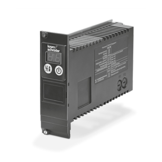
Technical data 9 .2 Operating controls A: 2-digit 7-segment display B: Reset/Information button to reset the system after a fault or to scan parameters on the display C: Mains switch D: Optical interface E: Type label 3 HE = 133.4 (5.3“) 8 TE = 40.6 (1.6“) PFU 780 ·... -
Page 66: Maintenance Cycles
Maintenance cycles 10 Maintenance cycles Burner control unit PFU requires little servicing. PFU 780 · Edition 02.12l... -
Page 67: Legend
Legend 11 Legend Display Blinking display Ready Safety interlocks (Limits) Start-up signal, pilot burner Start-up signal, main burner Digital input Ignition transformer Gas valve Air valve Purge Ext. air valve control Flame signal Operating signal, pilot burner Operating signal, main burner Fault signal Reset Input signal... -
Page 68: Glossary
Glossary 12 Glossary 12 .3 Ignition time t If no malfunction is detected during the waiting time 12 .1 Waiting time , the ignition time t then starts to elapse. Voltage is supplied to the pilot gas valve V1 and the ignition trans- former and the burner is ignited. -
Page 69: Safety Time During Operation T Sb
Glossary 12 .5 Safety time during operation t 12 .8 Safety interlocks (Limits) The limiters in the safety interlock (linking of all the rel- evant safety control and switching equipment for the use of the application, e.g. safety temperature limiter, minimum/maximum gas pressure) must isolate input ( ) from the voltage supply. -
Page 70: Continuous Operation
Glossary 12 .11 Continuous operation 12 .14 Mode of operation The gas burner runs continuously for more than 24 High demand mode or continuous mode hours. Operating mode, where the frequency of demands for operation made on a safety-related system is greater 12 .12 Air valve than one per year or greater than twice the proof-test The air valve can be used... -
Page 71: Feedback
Feedback Finally, we are offering you the opportunity to assess this “Technical Information (TI)” and to give us your opinion, so that we can improve our documents further and suit them to your needs. Clarity Comprehension Scope Found information quickly Coherent Too little Searched for a long time...
Need help?
Do you have a question about the Krom Schroder PFU 780 and is the answer not in the manual?
Questions and answers