Honeywell PRO4200 Series Installation Manual
Output module
Hide thumbs
Also See for PRO4200 Series:
- Installation manual (29 pages) ,
- Installation manual (24 pages) ,
- Installation manual (36 pages)

Related Manuals for Honeywell PRO4200 Series


Summary of Contents for Honeywell PRO4200 Series
- Page 1 PRO4200 Output Module (PRO42OUT) Installation Guide September 2020 © 2020Honeywell International, Inc. All rights reserved 800-25697V1...
- Page 2 All product and brand names are the service marks, trademarks, registered trademarks, or registered service marks of their respective owners. Printed in the United States of America. Honeywell reserves the right to change any information in this document at any time without prior notice.
-
Page 3: Table Of Contents
CONTENTS Notices Warnings and Cautions ..1 ....................Disclaimer ..2 .......................... Compliance ..3 ........................ - Page 4 (This page is left blank intentionally for double-sided printing.) www.honeywell.com...
-
Page 5: Notices
DO NOT ACCEPT VERBAL APPROVALS, BECAUSE THEY ARE NOT VALID. Honeywell never recommends using the PRO4200 or related products for use as a primary warning or monitoring system. Primary warning or monitoring systems should always meet local fire and safety code requirements. The installer must also test the system on a regular basis by instructing the end user in appropriate daily testing procedures. -
Page 6: Disclaimer
Customer harmless for any costs or damages including reasonable attorneys' fees which Customer may be required to pay as a result of the defective Product or the negligence of Honeywell, its agents, or its employees. -
Page 7: Compliance
Notices Compliance Customer shall hold harmless and indemnify Honeywell from and against all claims, demands, losses, and liability arising out of damage to property or injury to persons occasioned by or in connection with the acts or omissions of Customer and its agents and employees, and from and against all claims, demands, losses, and liability for costs of fees, including reasonable attorneys' fees, in connection therewith. - Page 8 3. Visually check contents. If damage is discovered, perform the following: • If shipping caused damage to the unit, a claim must be filed with the commercial carrier. • If any other defect is apparent, call for a return authorization. www.honeywell.com...
-
Page 9: Shipping Instructions
All Products sold or licensed by Honeywell include a warranty registration card which must be completed and returned to Honeywell by or on behalf of the end user in order for Honeywell to provide warranty service, repair, credit or exchange. All warranty... -
Page 10: Confidentiality
Confidentiality All software, drawings, diagrams, specifications, catalogs, literature, manuals and other materials furnished by Honeywell relating to the design, use and service of the Products shall remain confidential and shall constitute proprietary rights of Honeywell and Customer agrees to treat such information as confidential. Customer shall acquire no rights in the design of the Products or the related materials except to use such information solely for the purpose of and only during the time it sells the Products. - Page 11 Notices Confidentiality (This page is left blank intentionally for double-sided printing.) PRO4200 Output Module Installation Guide, Document 800-25697V1...
- Page 12 Notices Confidentiality www.honeywell.com...
-
Page 13: Installing The Pro4200 Output Module
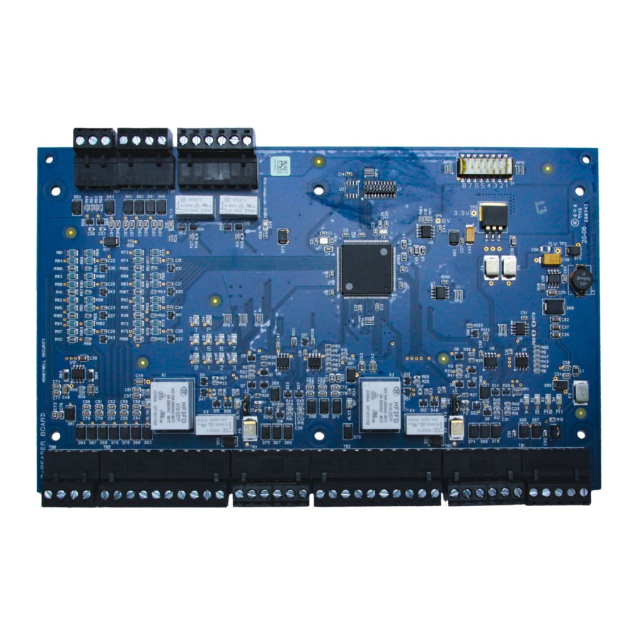
Installing the PRO4200 Output Module Description Installing the PRO4200 Output Module Description The Output Board provides connections for 16 relay outputs. You can either mount the board in a rack or open and flat. If you rack-mount the board, only one edge is accessible for wiring;... -
Page 14: Specification
0°C to +49°C, operating, -55°C to +85°C, storage Humidity 0% to 85% RHNC Set Up Table 1: PRO4200 Output Module Jumper Setting Jumper Setting Default Selected Port 1 RS-485 EOL terminator is not active Port 1 RS-485 EOL terminator is active www.honeywell.com... - Page 15 Installing the PRO4200 Output Module Set Up Table 2: PRO4200 Output Module DIP Switch Settings Selection ADDRESS 1* ADDRESS 2 ADDRESS 3 ADDRESS 4 ADDRESS 5 ADDRESS 6 ADDRESS 7 ADDRESS 8 ADDRESS 9 ADDRESS 10 ADDRESS 11 ADDRESS 12 ADDRESS 13 ADDRESS 14 ADDRESS 15...
-
Page 16: Led Operation
Table 3: LED Settings Mode LED D1 LED D2 Description Power-up Start power-up, hardware setup sequence Testing RAM Testing ROM and completing initialization FLASH LED D1 flashes 4 times after power-up is completed www.honeywell.com... - Page 17 Installing the PRO4200 Output Module LED Operation Table 3: LED Settings Mode LED D1 LED D2 Description Normal FLASH This is the processor heartbeat LED. It Operation flashes once every second. A short ON time (~20% duty cycle) indicates the board is offline or has lost serial communication with the Controller board.
-
Page 18: Power
2. TR- is the negative side of the transmit and receive differential signal. 3. GND is the signal ground. The wiring for this signal is required and optional. This signal must be connected to chassis GND. 4. Use 24 AWG low capacitance, two twisted-pair, shielded cable (Belden 9842 or equiv.). www.honeywell.com... -
Page 19: Wiring
Installing the PRO4200 Output Module Wiring For RS-485 Communication Connections, twist the blue pair together Note: and use as the common; use the orange pair as your data pair, observing polarity. Connect the external drain shield to the appropriate earth ground on one end. -
Page 20: Mounting Options
Mounting Options This board can be mounted on-edge in the rack-mount enclosure provided by Honeywell, or it can be mounted flat against any surface using standoffs under the mounting holes provided in each of the four corners of this board. -
Page 21: Wiring Diagram For Connectors 1 Through 8
Installing the PRO4200 Output Module Wiring Diagram for Connectors 1 through 8 Wiring Diagram for Connectors 1 through 8 Figure 1: PRO4200 Output Module Wiring: Connectors 1-8 Short OUTPUT BOARD RELAY0 NO together* RELAY0 C RELAY0 NC RELAY1 NO RELAY1 C RELAY1 NC RELAY2 NO RELAY2 C... -
Page 22: Wiring Diagram For Connectors 7 Through 10
+ 12V For RS-485 Communication Connections, twist the blue pair together and use as Note: the common; use the orange pair as your data pair, observing polarity. Connect the external drain shield to the appropriate earth ground on one end. www.honeywell.com... - Page 23 Installing the PRO4200 Output Module Wiring Diagram for Connectors 7 through 10 (This page is left blank intentionally for double-sided printing.) PRO4200 Output Module Installation Guide, Document 800-25697V1...
- Page 24 Installing the PRO4200 Output Module Wiring Diagram for Connectors 7 through 10 (This page is left blank intentionally for double-sided printing.) www.honeywell.com...
- Page 25 For more information: www.honeywellaccess.com Discover | Customer Portal Self-Service Product Support and Learning Management System https://honeywelldiscovertraining.com/login/discover/default.asp YouTube | Honeywell Help and Support https://www.youtube.com/channel/UCBEL6ouNV_LN5lEpYRujMTg/featured Honeywell Access Systems 135 W. Forest Hill Avenue Oak Creek, WI 53154 United States 800-323-4576 414-766-1798 Fax www.honeywellaccess.com...
Need help?
Do you have a question about the PRO4200 Series and is the answer not in the manual?
Questions and answers