Table of Contents
Advertisement
Quick Links
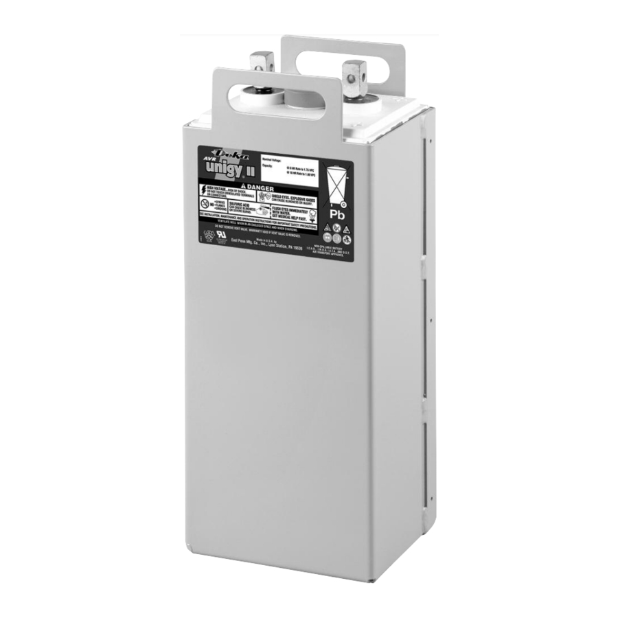
AVR45 SERIES–RAILWAY APPLICATION
INSTALLATION AND OPERATION MANUAL
Batteries, battery posts, terminals and related accessories
California
contain lead and lead compounds, and other chemicals known
Proposition 65
to the state of California to cause cancer and birth defects or
Warning:
other reproductive harm. Wash hands after handling.
Advertisement
Table of Contents

Related Manuals for Deka AVR45 Series


Summary of Contents for Deka AVR45 Series
- Page 1 AVR45 SERIES–RAILWAY APPLICATION INSTALLATION AND OPERATION MANUAL Batteries, battery posts, terminals and related accessories California contain lead and lead compounds, and other chemicals known Proposition 65 to the state of California to cause cancer and birth defects or Warning: other reproductive harm. Wash hands after handling.
-
Page 2: Table Of Contents
Electric Code for Maintenance Access ....4 Battery Cleaning ..........7 Hardware Torque Requirements ......4 Capacity Testing ..........7 System Installation APPENDIX A – Unigy II AVR45 Series Battery Cell Installation ..........5 Weight & Acid Volumes........8 Electrical Connection APPENDIX B – Voltage Compensation Chart Connector Assembly........5... -
Page 3: Safety Precautions
Procedures SAFETY PRECAUTIONS continued 10. The IEEE Standards contain additional information. Although all valve-regulated cells have the electrolyte immobilized Other standards may be relevant to your specific application. within the cell, the electrical hazard associated with batteries still exists. Work performed on these batteries should be done with IEEE 1184 –... -
Page 4: Grounding
Grounding Electric Code for Maintenance Access When grounding the battery string, proper techniques should Refer to ANSI/NFPA-70 National Electric Code for access and be applied per electrical standards, such as NEC and/or local working space requirements around the battery. A minimum of codes as well as User Manual of specific application. -
Page 5: System Installation
SYSTEM INSTALLATION Cell Installation 4. For multipost batteries (17 to 33 plate) a connector is to be installed at the battery system positive and negative end of each multiple cell configuration. This connector is used to electrically tie all same polarity posts together. Assemble system per the following details. -
Page 6: Final Assembly Check Procedure
Cell Voltage Final Assembly Check Procedure 1. For future identification of all cells, number individual cells in Although the charger must maintain the battery string voltage sequence, beginning with number one (1) at the positive end within ± 0.5%, individual cell voltages may vary by ± 0.05 volts of the battery. -
Page 7: Rectifier Ripple Voltage
Rectifier Ripple Voltage Battery Cleaning 1. Disconnect battery system from power source. FREQUENCY 2. Dust accumulation can be removed with cloth dampened Ripple that has a frequency greater than 667Hz (duration with clean water. less than 1.5ms) is acceptable, unless it is causing additional 3. -
Page 8: Appendix A Unigy Ii Avr45 Series Battery Weight & Acid Volumes
APPENDIX A Unigy II AVR45 Series Battery Weight & Acid Volumes Electrolyte Pure Acid Cell (per cell) (per battery) Battery Weight Type Volume Weight Weight liter AVR45-5 0.37 1.40 4.00 1.81 1.60 0.72 AVR45-7 0.52 1.96 5.60 2.54 2.24 1.02 AVR45-9 0.67... -
Page 9: Appendix Bvoltage Compensation Chart
APPENDIX B CHARGE CURRENT LIMITS VOLTAGE COMPENSATION CHART Max. Min. Float Cell ºC Voltage per ºF Charge Charge Type Battery Current (A) Current (A) AVR45-5 16.1 ≥ 35 2.230 ≥ 95 AVR45-7 24.1 AVR45-9 2.232 93.2 32.2 AVR45-11 40.2 12.1 2.234 91.4 AVR45-13... -
Page 10: Appendix C System Layout Drawings
APPENDIX C System Layout Drawings Drawing are representation of a 12V (6-cell) system 5-15 Plate Assembly 17 – 27 Plate Assembly... - Page 11 29 – 33 Plate Assembly...
-
Page 12: Battery Maintenance Report
www.dekabatteries.com East Penn Manufacturing Co. Lyon Station, PA 19536-0147 Phone: 610-682-3263 Fax: 610-682-4781 e-mail: reservepowersales@dekabatteries.com E.P.M. Form No. 2400 9/19 © 2019 by EPM Printed in U.S.A. All data subject to change without notice. No part of this document may be copied or reproduced, electronically or mechanically, without written permission from the company.
Need help?
Do you have a question about the AVR45 Series and is the answer not in the manual?
Questions and answers