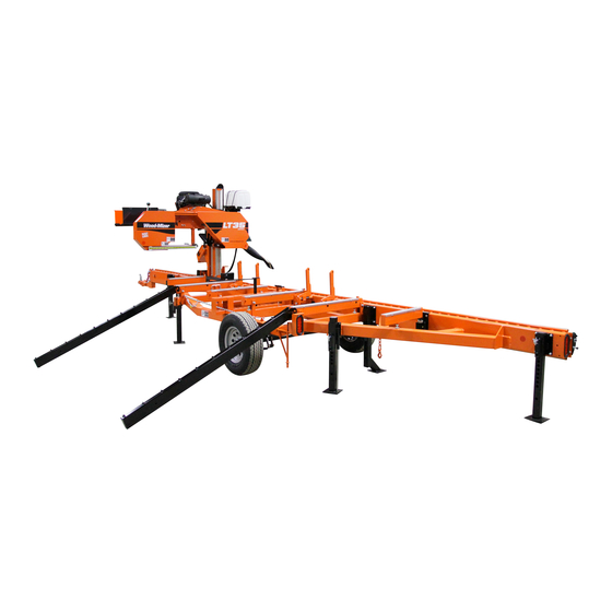
Wood-mizer LT35 Safety, Setup, Operation & Maintenance Manual
Sawmill
Hide thumbs
Also See for LT35:
Table of Contents
Troubleshooting

Related Manuals for Wood-mizer LT35


Summary of Contents for Wood-mizer LT35
- Page 1 ® Wood-Mizer Sawmill Safety, Setup, Operation & Maintenance Manual LT35 rev. A6.11 Safety is our #1 concern! Read and understand all safety information and instructions before oper- ating, setting up or maintaining this machine. Form #1773...
- Page 2 Printed in the United States of America, all rights reserved. No part of this manual may be reproduced in any form by any photographic, electronic, mechanical or other means or used in any information storage and retrieval system without written permission from Wood-Mizer 8180 West 10th Street Indianapolis, Indiana 46214...
-
Page 3: Table Of Contents
Table of Contents Section-Page SECTION 1 INTRODUCTION About This Manual.................1-1 Getting Service ..................1-2 General Contact Information..........1-2 Wood-Mizer Locations............1-3 Specifications ..................1-4 Customer and Sawmill Identification.............1-4 Warranty ....................1-6 SECTION 2 SAFETY Safety Symbols..................2-1 Safety Instructions ..................2-1 Electrical Lockout Procedures..............2-10 SECTION 3 SAWMILL SETUP Stationary Sawmill Setup ...............3-1... - Page 4 Hydraulic Problems (Optional Log Loader/Turner).......6-6 Simple Set Troubleshooting ..............6-9 Error Messages ..............6-9 Diagnostic Lights (After Mid-2016)........6-10 Diagnostic Lights (Prior to Mid-2016) .......6-11 Simple Set Up/Down Gear Settings Adjustment ....6-12 Simple Set PID Settings............6-13 Simple Set Troubleshooting (LT35) ........6-13 WMdoc072619 Table of Contents...
- Page 5 Table of Contents Section-Page SECTION 7 SAWMILL ALIGNMENT Routine Alignment Procedure ..............7-1 Blade Installation..............7-1 Saw Head Tilt................7-1 Blade Guide Arm Alignment ..........7-3 Blade Guide Vertical Tilt Alignment........7-5 Blade Guide Horizontal Tilt Adjustment.......7-7 Blade Guide Flange Spacing ..........7-8 Side Support Alignment............7-9 Blade Height Scale Adjustment...........7-11 Complete Alignment Procedure ............7-12 Frame Setup ...............7-12...
-
Page 6: Introduction
The information and instructions given in this manual do not amend or extend the limited warranties for the equipment given at the time of purchase. For general information regarding Wood-Mizer and our “Forest to Final Form” products, please refer to the All Products Catalog in your support package. -
Page 7: Getting Service
Getting Service Getting Service Wood-Mizer is committed to providing you with the latest technology, best quality and strongest customer service available on the market today. We continually evaluate our customers’ needs to ensure we’re meeting current wood-processing demands. Your com- ments and suggestions are welcome. -
Page 8: Wood-Mizer Locations
Brazilian Headquarters European Headquarters Serving Brazil Serving Europe, Africa, West Asia Wood-Mizer do Brasil Wood-Mizer Industries Sp z o.o. Rua Dom Pedro 1, No: 205 Bairro: Sao Jose Nagorna 114 Ivoti/RS CEP:93.900-000 62-600 Kolo, Poland Tel: +55 51 9894-6461/ +55 21 8030-3338/ +55 51 Phone: +48.63.26.26.000... -
Page 9: Specifications
*Manufacturer's Specification Customer and Sawmill Identification Each Wood-Mizer sawmill has a model number and a 17-digit Vehicle Identification Num- ber (VIN). In addition, when you pick up your mill, you will receive a customer number. Introduction WMdoc072619... - Page 10 Revision number Minor revision level A1.01 LT35 Serial number Full revision number VIN Plate MFG BY/FABRIQUÉ PAR: WOOD-MIZER, LLC 8180 W. 10th St. Indianapolis, IN 46214-2400 U.S.A. 317/271-1542 Or 800/553-0182 456D9271XSNDA1017 A1.01 04/15/2017 VIN/NIV: DATE: One or more patents may apply: U.S. Patent #6,655,429...
-
Page 11: Warranty
Wood-Mizer Limited Product Warranty Wood-Mizer LLC (“Warrantor”), an Indiana corporation with its principal place of business at 8180 West Tenth Street, Indianapolis, IN 46214-2400 USA, warrants to the purchaser (“Purchaser”) that for the time periods specifically stated herein and subject to the terms, conditions and limitations stated herein, the equipment... - Page 12 Introduction Warranty misuse, negligence, alterations, damage due to overload, abnormal conditions, excessive operation, acci- dent, or lack of performance of normal maintenance services. Several components which are used in the manufacture of the equipment but not manufactured by Warrantor, such as cant hooks, power plants, laser sights, batteries, tires, and trailer axles have warranties provided by the original equipment manufacturer (written copies available upon request).
- Page 13 This warranty cannot be amended, except in writing, which refers to this warranty that is signed by both Warrantor and Purchaser. © 2018 Wood-Mizer LLC – 8180 West 10 Street, Indianapolis, IN 46214...
-
Page 14: Safety
OWNER’S RESPONSIBILITY The procedures listed in this manual may not include all ANSI, OSHA, or locally required safety procedures. It is the owner/operator’s responsibility and not Wood-Mizer Products to ensure all operators are properly trained and informed of all safety protocols. - Page 15 Wood-Mizer sawmill. All Wood-Mizer mill owners are encouraged to become thoroughly familiar with these appli- cable laws and comply with them fully while using the mill.
- Page 16 Failure to follow this may result in serious injury or death. WARNING! Use ONLY water and Wood-Mizer Lube Addi- tive with the water lube accessory. Never use flammable fuels or liquids such as diesel fuel. If these types of liquids are necessary to clean the blade, remove it and clean with a rag.
- Page 17 Safety Safety Instructions WARNING! Charge the battery in a well ventilated area. Failure to fol- low this could result in serious injury or death. WARNING! Do not attempt to charge a frozen battery. Failure to follow this could result in serious injury or death. IMPORTANT! When working with batteries, use extreme care to avoid spilling or splashing electrolyte (dilute sulfuric acid) as it can destroy...
- Page 18 Safety Safety Instructions WARNING! Chock the trailer wheels to prevent movement before unhitching it from the towing vehicle. Failure to follow this could result in serious injury or death. WARNING! Put front outrigger down before moving saw head from the rest position.
- Page 19 Safety Safety Instructions KEEP PERSONS AWAY DANGER! Stay clear of the area between the trailer axle and saw carriage. Failure to follow this will result in serious injury or death. DANGER! Keep all persons out of the path of mov- ing equipment and logs when operating sawmill or loading and turning logs.
- Page 20 Safety Safety Instructions WARNING! Do not for any reason adjust the engine drive belt with the engine running. Doing so could result in serious injury or death. WARNING! Always keep clear of exiting sawdust. Keep hands, feet and any other objects away from the sawdust chute when operating sawmill.
- Page 21 Safety Safety Instructions WARNING! Always secure the saw head with a 5/16" chain with at least 1900 lbs. working load capacity before adjusting the mast pads. The saw head could fall, causing severe injury or death. WARNING! Always secure the saw head with a 5/16" chain with at least 1900 lbs.
- Page 22 Safety Safety Instructions WARNING! Always check trailer tires for proper inflation before towing sawmill. Failure to follow this could lead to tire failure resulting in prop- erty damage and/or serious injury or death. CAUTION! Move the optional hydraulic turner to provide maximum ground clearance before towing.
-
Page 23: Electrical Lockout Procedures
Safety Electrical Lockout Procedures WARNING! Never assume or take the word of another person that the power is off; check it out and lock it out. Failure to follow this could result in shock, burns, or death. WARNING! Do not wear rings, watches, or other jewelry while working around an open electrical circuit. - Page 24 Safety Electrical Lockout Procedures FAILURE TO LOCKOUT MAY RESULT IN: Burn Crush Shock Puncture Amputation Blindness Serious injury and death Electrocution TO CONTROL MAINTENANCE DANGERS: Lockout procedures must be followed (see OSHA regulation 1910.147). Never rely on machine stop control for maintenance safety (emergency stops, on/off ...
- Page 25 Safety Electrical Lockout Procedures PURPOSE This procedure establishes the minimum requirements for the lockout of energy isolating devices whenever maintenance or servicing is done on machines or equipment. It shall be used to ensure that the machine or equipment is stopped, isolated from all potentially hazardous energy sources and locked out before personnel perform any servicing or maintenance where the unexpected enervation or start-up of the machine or equipment or release of stored energy could cause injury.
- Page 26 Safety Electrical Lockout Procedures CAUTION! Return operating control(s) to neutral or "off" position after verifying the isolation of the equipment. 8. The machine or equipment is now locked out. RESTORING EQUIPMENT TO SERVICE When the servicing or maintenance is completed and the machine or equipment is ready to return to normal operating condition, the following steps shall be taken.
-
Page 27: Sawmill Setup
Sawmill Setup Stationary Sawmill Setup SECTION 3 SAWMILL SETUP Stationary Sawmill Setup Prepare the site: Area must be firm and level. The cement pad should be rated to support 6350 lbs./sq.ft. Use 5/8” diameter anchor bolts to secure feet. ... - Page 28 Sawmill Setup Stationary Sawmill Setup See Figure 3-2. Release the fender straps and lift up to remove the fenders. Stow until needed for transport.. qs-08 FIG. 3-2 2. Start the engine to enable the battery-operated accessories (See Section 3.6). Use the up/down switch on the control panel to raise the cutting head from the carriage rest pin.
- Page 29 See Figure 3-4. Transport Position Operation Position LT35-02 FIG. 3-4 NOTE: Always make sure the engine is running before operating the sawmill controls. Operating the controls without the engine running will result in power drainage from the battery. 4. Use the carriage forward/reverse switch (left side of control box) to move the cutting head toward the front (hitch end) of the mill.
-
Page 30: Portable Sawmill Setup
Sawmill Setup Portable Sawmill Setup See Figure 3-5. Pivot End Rail Side Support Bed Rail Stop Block SM0130B FIG. 3-5 Portable Sawmill Setup WARNING! Do not set up the mill on ground with more than a 10 degree incline. If setup on an incline is necessary, put blocks under one side of the mill or dig out areas for outrigger legs to keep mill level. - Page 31 Sawmill Setup Portable Sawmill Setup 1. Unhitch the mill from the vehicle. 2. Lower and set the front three outriggers. To lower, use the provided jack handle to lift the weight from the locking pin. If necessary, rotate the locking pin counterclockwise so that the inner roll pin is free from the outrigger channel notch, then pull the locking pin out to release the outrigger.
- Page 32 Sawmill Setup Portable Sawmill Setup CAUTION! Always make sure the engine is running before operating the sawmill controls. Operating the controls without the engine running will result in power drainage from the battery. 5. Remove the fenders by lifting them out of the slots. CAUTION! To prevent fender damage, remove fenders before operat- ing sawmill or loading logs.
-
Page 33: Replacing The Blade
Sawmill Setup Replacing The Blade Replacing The Blade DANGER! Always disengage the blade and shut off the sawmill engine before changing the blade. Failure to do so will result in serious injury. WARNING! Always wear gloves and eye protection when handling bandsaw blades. -
Page 34: Tensioning The Blade
Sawmill Setup Tensioning The Blade Tensioning The Blade The blade tensioner is factory-set so proper blade tension is achieved when the rubber spring is compressed 3/16” (4.8 mm). An indicator bolt is provided to indicate when the rubber spring has been compressed properly. To tension the blade, turn the blade tension handle up until it locks in place. -
Page 35: Tracking The Blade
Sawmill Setup Tracking The Blade Tracking The Blade 1. Make sure the blade housing covers are closed and all persons are clear of the open side of the saw head. 2. Start the engine. 3. Engage the blade, rotating the blade until the blade positions itself on the wheels. WARNING! Do not spin the blade wheels by hand. -
Page 36: Starting The Engine
Sawmill Setup Starting The Engine Cant Control 280013 FIG. 3-11 If the blade is too far out, back the blade onto the wheel by turning the cant control coun- terclockwise. If the blade is too far in, turn the cant control clockwise until the gullet of the blade is the correct distance from the front edge of the wheel. - Page 37 Sawmill Setup Starting The Engine DANGER! Always be sure the blade is disengaged and all persons are out of the path of the blade before starting the engine or motor. Failure to do so will result in serious injury. WARNING! Always wear eye, ear, respiration, and foot protection when operating the sawmill.
-
Page 38: Sawmill Operation
Sawmill Operation Optional Hydraulic Log Loader/Turner Control Operation SECTION 4 SAWMILL OPERATION Optional Hydraulic Log Loader/Turner Control Operation The hydraulic control levers become operational when the contacts at the bottom of the carriage touch the power strip on the frame tube. The hydraulic control levers will only work when the cutting head is close enough to the front end of the mill to touch the power strip. - Page 39 Sawmill Operation Optional Hydraulic Log Loader/Turner Control Operation 1. Remove the clamp from the sawmill bed so it will not get in the way of logs being loaded onto the bed. 2. Remove the two retaining pins holding the log loader in the towing position. See Figure 4-2.
-
Page 40: Loading, Turning And Clamping Logs
Sawmill Operation Loading, Turning And Clamping Logs 4. Lower the turner lever to completely lower the turner arm. Notice that after the turner arm is all the way down, the side support braces will begin to lower. Release the turner lever after the turner arm is lowered, but before the side supports begin to lower. - Page 41 Sawmill Operation Loading, Turning And Clamping Logs 3. Place the loading ramps on the two bed rails that will support the length of the log. NOTE: The loading ramps cannot be fastened securely to the bed rail located directly above the tire.
- Page 42 Sawmill Operation Loading, Turning And Clamping Logs 1. Use cant hooks or the optional manual log turner to rotate the log on the sawmill bed. See Log Turner Manual. 2. Spin the log against the side supports until it is turned the way you want it for the first cut. Optional Hydraulic Log Turner: 1.
-
Page 43: Up/Down Operation
Sawmill Operation Up/Down Operation 3. Make sure the side supports are positioned low enough for the blade to pass over them. If they are not, back the clamp off slightly and push the side supports down until they are positioned below the level of your first few cuts. 4. - Page 44 Sawmill Operation Up/Down Operation See Figure 4-5. The up/down switch is located on the right side of the control panel. Use the switch to raise or lower the cutting head. Hold the switch in position until the cutting head reaches the desired height, then release. Cutting Head Cutting Head Down...
-
Page 45: Simple Set Operation
Sawmill Operation Simple Set Operation Simple Set Operation Initial Setup See Figure 4-6. Turn the sawmill control key switch to the ON (#1) position. Simple Set will start up in manual mode. As the control powers up, the software revision is displayed. This information can be helpful should you require service. -
Page 46: Operation
Sawmill Operation Operation Press the Auto button to scroll back to the Set Speed menu or the Manual but- ton to exit. Operation Manual: With Simple Set in manual mode, operate the sawmill up/down system as nor- mal with the sawmill control up/down switch. The display will show a ‘D’ when the up/down switch is pushed down and a ‘U’... -
Page 47: Blade Guide Arm Operation
Sawmill Operation Blade Guide Arm Operation Blade Guide Arm Operation 1. Look down the length of the log to see its maximum width. The outer blade guide should be adjusted to clear the widest section of the log by less than 1" (25.4 mm). See Figure 4-7. -
Page 48: Power Feed Operation
Sawmill Operation Power Feed Operation Power Feed Operation See Figure 4-8. The power feed system moves the carriage forward and backward by using two switches on the control panel.. Carriage Reverse Carriage Forward Forward Feed Rate 3H1135-1 FIG. 4-8 CARRIAGE FEED RATE The carriage feed rate switch controls the speed at which the carriage travels forward. -
Page 49: Cutting The Log
Sawmill Operation Cutting The Log USING THE POWER FEED 1. To move the carriage forward, push the forward/reverse switch forward and turn the feed rate switch clockwise. HINT: To get a straight cut in the first part of the board, feed the blade into the log at a slow speed. -
Page 50: Edging
Sawmill Operation Edging 3. Engage the clutch lever to start the blade spinning. 4. Start the water lube if necessary to prevent sap buildup on the blade. See Section 4.10. 5. Feed the blade into the log slowly (See Section 4.6). -
Page 51: Blade Height Scale
Sawmill Operation Blade Height Scale 5. Loosen the clamp and turn the edged boards over to edge the other side. 6. Repeat steps 2-4. 7. Loosen the clamp and remove the boards that have good clean edges on both sides. Clamp the remaining flitches and repeat steps 2-5. -
Page 52: 4.10 Water Lube Operation
Sawmill Operation Water Lube Operation trim cut. Return the carriage for the second cut and lower it 1 1/8" (29 mm) below the orig- inal measurement. (The extra 1/8" (3 mm) allows for saw kerf and shrinkage of the lum- ber.) The yellow area on the scale identifies where the blade could encounter a side support or log clamp. -
Page 53: 4.11 Preparing The Sawmill For Towing
15 seconds. This will clean the blade of sap buildup. Wipe the blade dry with a rag before storing or sharpening. For further lubrication benefits, add one 12oz. (0.35L) bottle of Wood-Mizer Lube Additive to 5 gallons (18.9 liters) of water. Wood-Mizer Lube Additive enables some previously impossible timbers to be cut by significantly reducing resin buildup on the blade. - Page 54 Sawmill Operation Preparing The Sawmill For Towing 1. Move the saw carriage to the front end of the sawmill. Raise the rear outriggers. CAUTION! Be sure the outrigger base is adjusted properly before securing the FAO in position with the lock pin. Failure to do so will cause damage to the outrigger grease fitting.
- Page 55 Sawmill Operation Preparing The Sawmill For Towing CAUTION! Changes in temperature could cause increased pressure in the blade tensioner and loss of fluid from the gauge. Release the blade tension when the mill is not in use to avoid damage to the tensioner. 5.
- Page 56 Sawmill Operation Preparing The Sawmill For Towing See Figure 4-13. Loosen jam nut and turn bolt to raise or lower stop bolt 280015 FIG. 4-13 11. Engage the clutch lever. This keeps the drive belt tight and the motor from bouncing while traveling.
- Page 57 Sawmill Operation Preparing The Sawmill For Towing 14. Remove all loose objects from the bed of the mill. Store the outrigger jack handle in the bracket provided on the rear/loading-side outrigger guide. Reel in the winch cable and remove the winch handle if applicable. 15.
-
Page 58: Maintenance
Maintenance Wear Life SECTION 5 MAINTENANCE This section lists the maintenance procedures that need to be performed. See the Maintenance chart located after this section for a complete list of maintenance procedures and intervals. Keep a log of machine maintenance by recording in the machine hours and the date you perform each procedure. -
Page 59: Sawdust Removal
Maintenance Sawdust Removal 1. Check the rollers for performance and wear every blade change. Make sure the rollers are clean and spinning freely. If not, replace them. Replace any rollers which have worn smooth or have become cone shaped. Sawdust Removal WARNING! Before performing service near moving parts such as blades, pulleys, motors, belts and chains, first turn the key switch to... - Page 60 Maintenance Carriage Track, Wiper & Scraper 1. Clean track rails to remove any sawdust and sap buildup every eight hours of operation. Use a light-grade sandpaper or emery cloth to sand off any rust or other adhering parti- cles from the rails. CAUTION! Keep track rails free of rust.
-
Page 61: Vertical Mast Rails
Maintenance Vertical Mast Rails See Figure 5-1. Carriage track Remove track wiper, clean and lubricate Clean sawdust from housings 280005 Adjust track scrapers FIG. 5-1 Vertical Mast Rails WARNING! Before performing service near moving parts such as blades, pulleys, motors, belts and chains, first turn the key switch to the OFF (#0) position and remove the key. -
Page 62: Blade Wheel Belts
Rotate the blade wheel belts and check them for wear. Rotating the belts every 50 hours will provide longer belt life. Replace belts as necessary. Use only B57 belts supplied by Wood-Mizer. Drive Belt Adjustment WARNING! Disconnect and lockout power before performing any ser- vice to the electrical system. -
Page 63: Adjust The Drive Belt Tension
See Table 5-2. See the table below for drive belt tension specifications for your model sawmill. Measure the belt tension with a gauge. NOTE: Wood-Mizer offers a belt tension gauge (Part No. 016309) that will let you accurately measure the belt tension. -
Page 64: Adjust The Drive Belt Support
Maintenance Adjust the drive belt support 2. GAS OPTION ONLY: After tensioning the drive belt, check the throttle linkage and adjust if necessary. NOTE: With the clutch handle engaged, the throttle linkage should move the throttle lever to full speed. To adjust, loosen the throttle linkage adjustment nuts and slide the throttle linkage down. - Page 65 Maintenance Hydraulic System and allow the fluid to maintain its hot end performance. If humidity is not a problem, drain and replace one gallon (3.8 liters) of fluid every year to prevent fluid wear. See Figure 5-3. If you are operating in temperatures -20° to 100° F (-29° to 38° C), use an all-weather hydraulic fluid such as Conoco MV32.
-
Page 66: 5.10 Up/Down System
Maintenance Up/Down System 5.10 Up/Down System WARNING! Before performing service near moving parts such as blades, pulleys, motors, belts and chains, first turn the key switch to the OFF (#0) position and remove the key. If the key is turned on and moving parts activated, serious injury may result. -
Page 67: 5.11 Power Feed
Drain and refill the gearbox with 24 (0.7L) ounces of oil after every 5000 hours of sawmill operation or every 2 years, whichever comes first. Wood-Mizer offers replacement gear oil in 8 ounce (0.24L) bottles. 5.11 Power Feed WARNING! -
Page 68: 5.12 Charging The Battery
Maintenance Charging The Battery See Figure 5-6. 3H0018B Feed Chain Adjustment Nuts FIG. 5-6 5.12 Charging The Battery DANGER! Batteries expel explosive gases. Keep sparks, flames, burning cigarettes, or other ignition sources away at all times. Always wear safety goggles and a face shield when working near batteries. Failure to do so will cause serious injury. - Page 69 Maintenance Charging The Battery Use extreme care to avoid spilling or splashing electrolyte (which is dilute sulfuric acid) as it can destroy clothing and burn the skin. EMERGENCY TREATMENT FOR CONTACT WITH BATTERY COMPONENTS (LEAD/SUL- FURIC ACID) per SDS (Safety Data Sheet): EYE CONTACT Sulfuric Acid and Lead: Flush eyes immediately with large amounts of water for at least 15 minutes while lifting lids.
-
Page 70: 5.13 Maintenance Chart
Maintenance Maintenance chart IMPORTANT: Be careful not to overcharge the battery, especially when using a high-rate or “boost” charger (40 amps or higher). These are intended to quickly charge a good battery that is discharged. They are not intended for unattended or long-term charging. 8. - Page 71 Maintenance Maintenance chart Inspect hydraulic pump (Optional Loader/Turner) motor See Section 5.9 750 hours brushes Maintenance WMdoc072619 5-14...
-
Page 72: Troubleshooting Guide
Troubleshooting Guide Sawing Problems SECTION 6 TROUBLESHOOTING GUIDE Sawing Problems WARNING! Before performing service near moving parts such as blades, pulleys, motors, belts and chains, first turn the key switch to the OFF (#0) position and remove the key. If the key is turned on and moving parts activated, serious injury may result. -
Page 73: Electrical Problems
Troubleshooting Guide Electrical Problems PROBLEM CAUSE SOLUTION Height Adjustment Jumps or Up/down chain improperly Adjust up/down chain. Stutters When Moving Up or adjusted. Down. Lumber Is Not Square Vertical side supports not Adjust side supports. square to bed Blade not parallel to bed rails Adjust bed rails parallel to blade. -
Page 74: Power Feed Problems
Troubleshooting Guide Power Feed Problems PROBLEM CAUSE SOLUTION Worn up/down motor or motor Replace up/down motor or motor brushes. brushes. Up/down Or Power Feed Worn contacts in switch. Replace switch. Motors Do Not Work. Burned-out motor. Replace motor. Bad connection on battery Check for loose wire or terminal connec- post or loose wire. - Page 75 Troubleshooting Guide Power Feed Problems Access the power feed control module in the control box, With the key/toggle switch on put the drum switch/joystick in the forward position, When turning the speed control, check the lights on the control module. ...
- Page 76 Troubleshooting Guide Power Feed Problems If the OV light is on, there is an over voltage condition. Perform a continuity check on the free wheeling diode with the diode removed from the block. There should be continuity only one direction. See Figure 6-2.
-
Page 77: Power Feed Variable Feed Rate Switch Test
Troubleshooting Guide See Figure 6-3. FIG. 6-3 The saw head does not travel in reverse but forward works: Check the drum switch connections. Power Feed Variable Feed Rate Switch Test With the feed rate dial switch all the way down, move the shaft of the dial back and forth to see if there is a jerky response. - Page 78 Replace solenoid if necessary. NOTE: The ing solenoid solenoid is not a standard automotive type. Order from Wood-Mizer only Defective pump motor Remove motor from pump and inspect. Repair or replace as necessary No Response From The Electric contact spring Check contact spring.
- Page 79 Troubleshooting Guide Hydraulic Problems (Optional Log Loader/Turner) PROBLEM CAUSE SOLUTION Low fluid level Check fluid level. Add an all-season hydraulic fluid such as Amoco Rycon Oil MV or Mobil Multipurpose ATF (automatic transmission fluid) until level is 4 - 4 1/2" (100 - 114mm) from bottom of reservoir with all cylinders retracted Pressure relief valve...
-
Page 80: Simple Set Troubleshooting
Troubleshooting Guide Simple Set Troubleshooting PROBLEM CAUSE SOLUTION Low air temperature caus- Allow fluid to warm up. Synthetic fluids are ing fluid to thicken available that allow for hydraulic operation in cold weather conditions (Univis HVI 13) Hydraulic Turner Goes Up Dirt in sequence valve Remove sequence valves and clean thor- Before Or At Same Time... -
Page 81: Diagnostic Lights (After Mid-2016)
Troubleshooting Guide Diagnostic Lights (After Mid-2016) Diagnostic Lights (After Mid-2016) See Figure 6-4. LED indicator lights are provided on the encoder sensor housing and the display circuit board and H-bridge module inside the Simple Set control box. Observing the LED lights during operation can help identify problems with the sensor, switches or Simple Set control. -
Page 82: Diagnostic Lights (Prior To Mid-2016)
Troubleshooting Guide Diagnostic Lights (Prior to Mid-2016) blade reaches the increment value, the H-bridge D2, D3, D4 LEDs will turn off. Diagnostic Lights (Prior to Mid-2016) See Figure 6-5. LED indicator lights are provided on the encoder sensor housing and the display circuit board and H-bridge module inside the Simple Set control box. -
Page 83: Simple Set Up/Down Gear Settings Adjustment
4. Use the Up/Down arrow buttons to set the value of the Gear Setting as shown in the table below. See Table 6-1. Models Revision Gear Setting InvGear Setting LT40 (Default) 0.0938 (Default) No (Default) LT35/LT35HD Any revision (upgraded with 0.1170 Up/Down Kit 074029) LT35/LT35HD A1.00 - A1.02 0.2250 LT35/LT35HD A2.00 - A2.01 0.3492 LT35/LT35HD A3.00 - A4.01... -
Page 84: Simple Set Pid Settings
PGain 1.0, DGain 0.0 and IGain 0.0. 4. Press the Manual button to return to the main menu. Simple Set Troubleshooting (LT35) Follow the instructions below to solve the possible power feed problems. If the saw head does not go up or down: Disconnect the wires to the up/down motor, ... - Page 85 Troubleshooting Guide Simple Set Troubleshooting (LT35) If there is no voltage reading: Check the lights on the control module: the red light when in the down position and the green light when in the up position, If there are no lights, check for voltage at the drum switch terminals.
-
Page 86: Sawmill Alignment
Routine Alignment Procedure SECTION 7 SAWMILL ALIGNMENT The Wood-Mizer sawmill is factory aligned. Two alignment procedures are available to realign the sawmill if necessary. The Routine Alignment instructions should be performed as necessary to solve sawing problems not related to blade performance. The Complete Alignment procedure should be performed approximately every 1500 hours of operation (sooner if you regularly transport the sawmill over rough terrain). - Page 87 Sawmill Alignment Saw Head Tilt See Figure 7-1. A + 1/16” SM0257 FIG. 7-1 3. Measure from the blade to the bed rail near the outer blade guide assembly. This mea- surement should be 1/16" (1.5 mm) higher than the inner measurement or 14 13/16" (376.5 mm).
-
Page 88: Blade Guide Arm Alignment
Sawmill Alignment Blade Guide Arm Alignment from the blade to the bed rails and adjust the horizontal adjustment nuts until the outside of the saw head is 1/16" (1.5mm) higher than the inside. Adjust nuts in to raise saw head; Adjust nuts out to lower saw head. - Page 89 Sawmill Alignment Blade Guide Arm Alignment 1. Adjust the blade guide arm out to 1/2" (13 mm) from fully open. See Figure 7-3. Use the inside top and bottom screws to adjust the arm up until the slide pad touches the saw head brace tube. Tighten the jam nuts. 280011 Adjust inside top Adjust outside top...
-
Page 90: Blade Guide Vertical Tilt Alignment
Sawmill Alignment Blade Guide Vertical Tilt Alignment See Figure 7-4. With the blade guide arm still all the way in toward the other blade guide, tighten all the side screws until they touch the arm. Back the screws off 1/4 turn and tighten the jam nuts. - Page 91 Sawmill Alignment Blade Guide Vertical Tilt Alignment 1. Open the adjustable blade guide arm 1/2" (13 mm) from full open. 2. Clip the alignment tool on the blade. Position the tool close to the outer blade guide assembly. Be sure the tool does not rest on a tooth or burr, and is lying flat against the bottom of the blade.
-
Page 92: Blade Guide Horizontal Tilt Adjustment
Sawmill Alignment Blade Guide Horizontal Tilt Adjustment 7. Move the blade guide alignment tool close to the inner blade guide roller assembly and repeat the above steps. Adjust the vertical tilt of the inner blade guide if necessary. Blade Guide Horizontal Tilt Adjustment If the blade guides are tilted in the wrong direction horizontally, the back of the blade may contact the flange as the roller is spinning down, causing it to push the blade away from the guide roller. -
Page 93: Blade Guide Flange Spacing
Sawmill Alignment Blade Guide Flange Spacing left screw and tighten the right screw. Tighten the jam nuts and recheck the tilt of the blade. Horizontal Tilt Adjustment Screws Adjust screws right to tilt roller left; Adjust screws left to tilt roller right 3H0802-9 FIG. -
Page 94: Side Support Alignment
Sawmill Alignment Side Support Alignment 1. Measure the distance between the flange on the outer blade guide roller to the back edge of the blade. This distance should measure 1/8" (3.0 mm). Adjust the roller back or for- ward if necessary. See Figure 7-9. - Page 95 Sawmill Alignment Side Support Alignment than 1/32" (0.8 mm) greater than the distance at the base of the side support (’A’). Adjust the horizontal tilt of the side support if necessary. See Figure 7-10. Loosen the two adjustment plate mounting bolts. Use a mallet to move the plate until the side support is parallel to the bed tube in the horizontal position.
-
Page 96: Blade Height Scale Adjustment
Sawmill Alignment Blade Height Scale Adjustment See Figure 7-11. Loosen the side support mounting bolt. Use a 3/8" ratchet to rotate the pin until the side support is square to the bed. Alignment Tubes (2) Place square against side support Loosen mounting bolt SM0272-1 Use 3/8”... -
Page 97: Complete Alignment Procedure
If your sawmill has a trailer axle and adjustable outriggers, adjust the outriggers as fol- lows: LT35: Adjust the two outriggers on the main frame tube down just enough to lift weight from the trailer tire. All Portable Sawmills: Adjust the two outer outriggers down just so they touch the ground but do not bear weight. -
Page 98: Blade Installation
Sawmill Alignment Blade Installation Blade Installation 1. Remove the blade and replace the blade wheel belts. New blade wheel belts are required to perform the complete alignment procedure. 2. Blow sawdust off of the blade guide assemblies. Remove sawdust from the blade hous- ings. - Page 99 Sawmill Alignment Blade Wheel Alignment 1. Use the blade guide alignment tool to check the vertical alignment of each blade wheel. Attach the tool to the blade near the inner blade guide mount. Be sure the tool does not rest on a tooth or burr, and is lying flat against the bottom of the blade. See Figure 7-12.
- Page 100 Sawmill Alignment Blade Wheel Alignment nut on the top adjustment screw and tighten the screw. Tighten the top and bottom jam nuts. 150210-14 Blade Guide Alignment Tool Adjust vertical adjustment screws down to tilt drive-side blade wheel up; Adjust screws up to tilt wheel down FIG.
- Page 101 Sawmill Alignment Blade Wheel Alignment nut on the bottom adjustment screw and tighten the screw. Tighten the top and bottom jam nuts. Adjust vertical adjustment screws up to tilt idle-side blade wheel down; Adjust screws down to tilt wheel up 280012 FIG.
- Page 102 Sawmill Alignment Blade Wheel Alignment See Figure 7-15. The horizontal tilt of the blade wheel should be adjusted so that the gul- let of an 1-1/4" blade is 1/8" (3 mm) out from the front edge of the wheel (±1/32 [0.75 mm]).
-
Page 103: Bed Rail Adjustment
Sawmill Alignment Bed Rail Adjustment ter turn. Loosen the jam nut on the left adjustment screw and tighten the screw. Tighten the left and right jam nuts. To move the blade out on the wheel, loosen the left adjustment screw one quarter turn. Loosen the jam nut on the right adjustment screw and tighten the screw. - Page 104 Sawmill Alignment Bed Rail Adjustment mm) from the top of the clamp. Use a rule to determine the actual distance of the blade to the clamp. See Figure 7-18. FIG. 7-18 2. Adjust the front pivot rail 90° to the main bed tube. 3.
- Page 105 Sawmill Alignment Bed Rail Adjustment See Figure 7-19. Loosen the locking set screws and turn the inner height adjustment nut to adjust the height of the inner end of the pivot rail. Loosen the jam nut and turn the outer adjustment bolt to adjust the height of the outer end of the pivot rail.
-
Page 106: Blade Guide Installation
Blade Guide Installation Each Wood-Mizer sawmill has two blade guide assemblies that help the blade maintain a straight cut. The two blade guide assemblies are positioned on the saw head to guide the blade on each side of the material being cut. -
Page 107: Blade Guide Arm Alignment
Sawmill Alignment Blade Guide Arm Alignment See Figure 7-21. Top Vertical Adjustment Jam Nut Tilt Adjustment Screws (4) Blade Guide Shaft Centered Roller Flange In Block Bottom Vertical Adjustment Jam Nut 3H0802-15 FIG. 7-21 Blade Guide Arm Alignment The blade guide arm moves the outer blade guide in and out. If the arm becomes loose, the blade guide will not deflect the blade properly, causing inaccurate cuts. - Page 108 Sawmill Alignment Blade Guide Arm Alignment Adjust the blade guide arm in all the way toward the other blade guide. 3. Use the outside top and bottom screws to adjust the arm up until the slide pad touches the saw head brace tube. Tighten the jam nuts. NOTE: When adjusting the blade guide arm screws, be careful not to tighten the screws too much or put the arm in a bind.
-
Page 109: Blade Guide Deflection
Sawmill Alignment Blade Guide Deflection Blade Guide Deflection 7. Raise the saw head until the blade is 15" (375 mm) above a bed rail. Measure the actual distance with a tape from the top of the rail to the bottom of the blade.Make sure the two vertical adjustment set screws are threaded into the blade guide shaft until they touch each other. - Page 110 Sawmill Alignment Blade Guide Vertical Tilt Alignment See Figure 7-25. Clip tool to blade SM0069B FIG. 7-25 3. Move the carriage so that the front end of the tool is positioned above the bed rail. Mea- sure the distance from the bed rail to the bottom edge of the tool. 4.
-
Page 111: Blade Guide Horizontal Tilt Adjustment
Sawmill Alignment Blade Guide Horizontal Tilt Adjustment Blade Guide Horizontal Tilt Adjustment If the blade guides are tilted in the wrong direction horizontally, the back of the blade may contact the flange as the roller is spinning down, causing it to push the blade away from the guide roller. -
Page 112: Blade Guide Flange Spacing
Sawmill Alignment Blade Guide Flange Spacing left screw and tighten the right screw. Tighten the jam nuts and recheck the tilt of the blade. Horizontal Tilt Adjustment Screws Adjust screws right to tilt roller left; Adjust screws left to tilt roller right 3H0802-9 FIG. -
Page 113: Side Support Alignment
Sawmill Alignment Side Support Alignment 1. Measure the distance between the flange on the outer blade guide roller to the back edge of the blade. This distance should measure 1/8" (3.0 mm). Adjust the roller back or for- ward if necessary. See Figure 7-29. - Page 114 Sawmill Alignment Side Support Alignment than 1/32" (0.8 mm) greater than the distance at the base of the side support (’A’). Adjust the horizontal tilt of the side support if necessary. See Figure 7-30. Loosen the two adjustment plate mounting bolts. Use a mallet to move the plate until the side support is parallel to the bed tube in the horizontal position.
-
Page 115: Clamp Stop/Stop Bolt Adjustment
Sawmill Alignment Clamp Stop/Stop Bolt Adjustment See Figure 7-31. Loosen the side support mounting bolt. Use a 3/8" ratchet to rotate the pin until the side support is square to the bed. Alignment Tubes (2) Place square against side support Loosen mounting bolt SM0272-1 Use 3/8”... -
Page 116: Saw Head Tilt
Sawmill Alignment Saw Head Tilt See Figure 7-32. Loosen the clamp stop bolts and adjust the clamp stop until it touches the string. Loosen the jam nut and adjust the bolt on the middle-rear bed rail until it touches the string. Adjust stop bolt against string String across... - Page 117 Sawmill Alignment Saw Head Tilt 1. Move the saw carriage so the blade is positioned over a bed rail. Adjust the blade guide arm to 1/2" (13 mm) from full open. The saw head should still be adjusted so the blade is 14 3/4"...
-
Page 118: Blade Height Scale Adjustment
Sawmill Alignment Blade Height Scale Adjustment from the blade to the bed rails and adjust the horizontal adjustment nuts until the outside of the saw head is 1/16" (1.5mm) higher than the inside. Adjust nuts in to raise saw head; Adjust nuts out to lower saw head. - Page 119 Sawmill Alignment Blade Height Scale Adjustment Retighten the bracket mounting bolts. For example, if the measurement from the down-set tooth of the blade to the bed rail was 14 3/4" (375 mm), make sure the indicator reads 14 3/4" (375 mm) on the scale. Blade Height Inch Scale Indicator...
-
Page 120: Hydraulic Information (Optional Loader/Turner)
Hydraulic Information (Optional Loader/Turner) Hydraulic Schematic SECTION 8 HYDRAULIC INFORMATION (OPTIONAL LOADER/TURNER) Hydraulic Schematic 300156 OPTIONAL HYDRAULIC LOG LOADER/TURNER WMdoc072619 Hydraulic Information (Optional Loader/Turner) -
Page 121: Hydraulic Layout Diagram
Valve (Yellow) “T” Fitting 300157 H4 (Red) Elbow Fitting OPTIONAL HYDRAULIC LOADER/TURNER LAYOUT DIAGRAM. Hydraulic Components Wood-Mizer Description Part.# C1, C2 P12847 Hyd. Cylinder, 3" Bore X 8" Stroke P12846 Hyd. Cylinder, 2 1/2" Bore X 8" Stroke Hydraulic Information (Optional Loader/Turner) WMdoc072619... -
Page 122: Hydraulic Hoses
Valve, 4-Way Hydraulic V2, V3 015750 Valve, Hydraulic 5GPM Velocity Fuse V4, V5 A09207 Sequence Valve Hydraulic Hoses Color Code LENGTH Application Wood-Mizer "A" Part No. LOADING ARM BRANCH TOP Green 018020 62" 1/4” Yellow LOADING ARM BRANCH BASE 018021 64"... -
Page 123: Electrical Information
Electrical Information Wiring Diagrams, D24 SECTION 9 ELECTRICAL INFORMATION Wiring Diagrams, D24 Battery CHASSIS 1 AWG BLK 1 AWG BLK 1 AWG BLK 1 AWG BLK 1 AWG BLK 1 AWG BLK Positive Contact Strip Assy 225A GND Contact Assy Hyd Motor Solenoid Hyd Motor .104... - Page 124 Electrical Information Wiring Diagrams, D24 1.118 1.120 10 AWG BLK Mosfet Module 16 AWG BLK Controller, Power Feed BLACK BROWN POT(-) 16 AWG BLU BLUE GATE POT(W) 16 AWG GRN GREEN SENSE VIOLET Potentiometer POT(+) 16 AWG RED 10 AWG BLU 18 AWG RED 18 AWG BLK 12 AWG BLK...
-
Page 125: Component List, D24
Electrical Information Component List, D24 Component List, D24 Component List Item Mfg. Part No. Mfg. Wood-Mizer Description Part No. 5M, 7M 016371 Wood-Mizer 016371 Solenoid Kit, 200A 12V SPST Cont. Duty 052365 Wood-Mizer 052365 Capacitor Assembly, P/F Filter 75105 Various... -
Page 126: Engine Harness Wiring, D24
Electrical Information Engine Harness Wiring, D24 Engine Harness Wiring, D24 3H1220-1 35doc072619 Electrical Information... - Page 127 Electrical Information Engine Harness Wiring, D24 3H1220-2 Electrical Information 35doc072619...
- Page 128 Electrical Information Engine Harness Wiring, D24 3H1220-3 35doc072619 Electrical Information...
- Page 129 Electrical Information Engine Harness Wiring, D24 3H1220-4 Electrical Information 35doc072619...
-
Page 130: Wiring Diagrams, G25
Electrical Information Wiring Diagrams, G25 Wiring Diagrams, G25 35doc072619 Electrical Information... - Page 131 Electrical Information Wiring Diagrams, G25 Electrical Information 35doc072619...
-
Page 132: Component List, G25
5M, 7M 016371 Wood-Mizer 016371 Solenoid Kit, 200A 12V SPST Cont. Duty ALT1 050287 Delphi 050287 Alternator, 105A 052365 Wood-Mizer, LLC 052365 Capacitor Assembly, P/F Filter 75105 Various 053464 Breaker, 10A Manual Reset 75105 Various 053464 Breaker, 10A Manual Reset... -
Page 133: Index
INDEX alignment leveling logs main bed rails 7-18 loading logs battery troubleshooting problems maintenance blade guide blade blade wheel belts breakage, troubleshooting carriage track/wipers installation drive belt tensioning hydraulic system tracking mast rails miscellaneous blade guide arm part wear life operation 4-10 power feed... - Page 134 scale blade height operation 4-14 inch height 4-14 quarter inch 4-15 service information branch locations customer & sawmill ID general contact info setup portable sawmill stationary sawmill simple set operation troubleshooting electrical problems hydraulic problems power feed problems sawing problems turning logs up/down operation...
Need help?
Do you have a question about the LT35 and is the answer not in the manual?
Questions and answers
how do you put the cable in for lt35 manual log turner
To install the cable for the Wood-Mizer LT35 manual log turner:
1. Remove the winch cable from the log turner (if applicable).
2. Route the cable over the top of the log.
3. Wrap the cable around and underneath the log.
4. Hook the cable to the third hole in the log clamp bracket.
This answer is automatically generated