
Related Manuals for Rohde & Schwarz TS-PSAM


Summary of Contents for Rohde & Schwarz TS-PSAM
- Page 1 ® R&S TS-PSAM Analog Stimulus Measurement Module User Manual (;ZðÜ<) 1142987812 Version 12...
- Page 2 ® This manual describes the following R&S TSVP module: ● ® R&S TS-PSAM © 2021 Rohde & Schwarz GmbH & Co. KG Mühldorfstr. 15, 81671 München, Germany Phone: +49 89 41 29 - 0 Email: info@rohde-schwarz.com Internet: www.rohde-schwarz.com Subject to change – data without tolerance limits is not binding.
- Page 3 Safety Instructions Instrucciones de seguridad Sicherheitshinweise Consignes de sécurité Risk of injury and instrument damage The instrument must be used in an appropriate manner to prevent personal injury or instrument damage. ● Do not open the instrument casing. ● Read and observe the "Basic Safety Instructions" delivered as printed brochure with the instrument.
- Page 4 Gefahr von Verletzungen und Schäden am Gerät Betreiben Sie das Gerät immer ordnungsgemäß, um elektrischen Schlag, Brand, Verletzungen von Personen oder Geräteschäden zu verhindern. ● Öffnen Sie das Gerätegehäuse nicht. ● Lesen und beachten Sie die "Grundlegenden Sicherheitshinweise", die als gedruckte Broschüre dem Gerät beiliegen. ●...
- Page 5 At the back, the R&S TS-PSAM module is connected to the cPCI control bus and the PXI trigger bus. Instead of using the front connector, measurement signals can be routed via the R&S CompactTSVP's analog measuring bus.
-
Page 6: Measuring Functions
GND. The measurement unit and the DC voltage source can also be operated independently of one another. In the in-circuit test (ICT), the R&S TS-PSAM module performs the following measuring tasks: ● Discharging capacitors ●... - Page 7 ® Usage R&S TS-PSAM Features of the R&S TS-PSAM In this method, a constant current is applied and the voltage is measured. (see Fig- ure 1-1 Figure 1-2) Figure 1-1: Cross-connection for 2-wire resistance measuring in Mode C Figure 1-2: Cross-connection for 4-wire resistance measuring in Mode C ●...
- Page 8 ® Usage R&S TS-PSAM Features of the R&S TS-PSAM Figure 1-3: Cross-connection for 2-wire resistance measuring in Mode V Figure 1-4: Cross-connection for 4-wire resistance measuring in Mode V User Manual 1142.9878.12 ─ 12...
- Page 9 ® Usage R&S TS-PSAM Features of the R&S TS-PSAM 1.2.2.2 ICT Measurements with R&S TS-PICT On this topic, see also Figure 1-5 Figure 1-6. Further in-circuit measurements can be made in conjunction with the R&S TS-PICT module (ICT expansion module). These are: ●...
- Page 10 ® Usage R&S TS-PSAM R&S TS-PDC Features Figure 1-6: Cross-connection in a guarded impedance measurement (6-wire) 1.3 R&S TS-PDC Features The R&S TS-PDC module is used as a floating DC voltage source for the R&S TS- PSAM module. It is configured with two identical DC/DC converters. The following floating direct voltages are obtained from an input voltage of 5 VDC: ●...
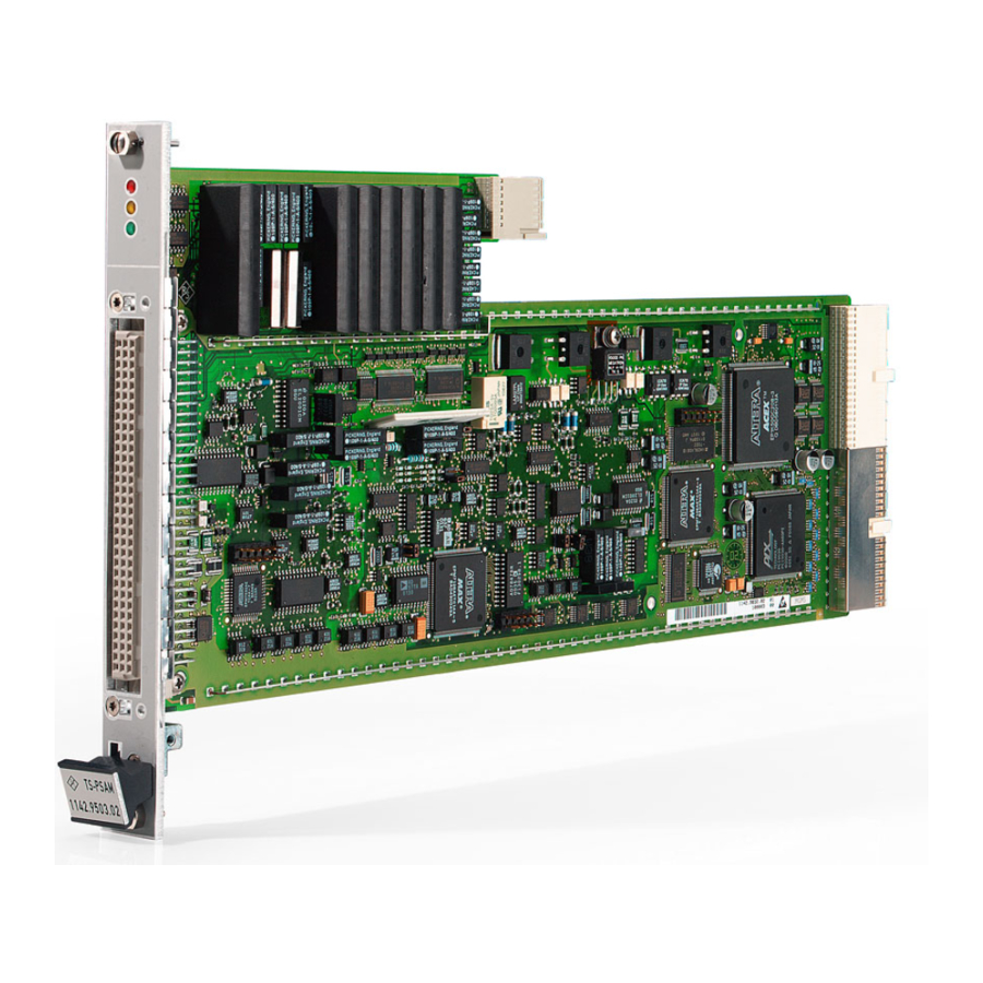
- Page 11 View R&S TS-PSAM 2 View Figure 2-1shows the R&S TS-PSAM module without the associated TS-PDC rear I/O module. The R&S TS-PDC rear I/O module is shown in Figure 2-2. Figure 2-1: View of the R&S TS-PSAM module User Manual 1142.9878.12 ─ 12...
- Page 12 ® View R&S TS-PSAM Figure 2-2: View of the R&S TS-PDC rear I/O module. The Module R&S TS-PDC exists in 3 different models: ● Grouted in a black housing - version up to 1.8 (1157.9804.02 obsolete) ● Encapsulated in metal housing with cooling fins - version 1.9 (1157.9804.02 obso- lete) ●...
-
Page 13: Block Diagrams
Block diagrams R&S TS-PSAM 3 Block diagrams Figure 3-1shows the block diagram of the R&S TS-PSAM module and Figure 3-2 shows the block diagram of the R&S TS-PDC module. Figure 3-3 is a simplified func- tional block diagram of both modules in the R&S CompactTSVP. - Page 14 Block diagrams R&S TS-PSAM Regulator primary -15 V DC-Transducer Regulator ON/OFF -15 V INHIBIT Figure 3-2: Block Diagram of R&S TS-PDC Figure 3-3: Functional block diagram of R&S TS-PSAM with R&S TS-PDC in the R&S CompactTSVP User Manual 1142.9878.12 ─ 12...
- Page 15 Figure 4-1. The R&S TS-PSAM module is designed as a long cPCI plug-in module for mounting in the front of the R&S CompactTSVP. The board height of the module is 3 HU (134 mm). To ensure that it is inserted correctly into the Compact TSVP, the front panel is fur- nished with a locating pin.
- Page 16 On this topic, see also Figure 4-2. Three light-emitting diodes (LEDs) are located on the front of the R&S TS-PSAM mod- ule to show the current status of the module. These LEDs have the following mean- ings: Figure 4-2: Arrangement of LEDs on the R&S TS-PSAM module Table 4-2: LEDs on the R&S TS-PSAM module...
- Page 17 Display Elements of the R&S TS-PDC Module The R&S TS-PDC module must always use the corresponding rear I/O slot for the main module (e.g. R&S TS-PSAM module). The R&S TS-PDC module must always be inserted in the corresponding rear I/O slot of the R&S TS-PSAM module.
- Page 18 ® Layout R&S TS-PSAM Display Elements of the R&S TS-PDC Module In the switched-on state, the green LED PWR indicates the power-on state. In fault free operation additionally the 8 green LEDs for each generated output voltage light up. In case of overload or over temperature the module shuts down by itself. The error is signalized by the red LED ERR.
-
Page 19: Function Description
It is therefore strongly recommended to configure the R&S TS-PSAM for “voltage measurement” before the input is connected with the test points. Matrix relays The stimulus and measurements can be cross-connected in any permutation through a full matrix to a local analog bus (8-wires LABx). - Page 20 Function Description R&S TS-PSAM Function description of the R&S TS-PSAM Module The channels of the single components MU and DSC cannot be cross-connected if the resistance measurement function (rspsam_ConfigureMeasurement) is configured. In this case, use the DMM channels. During resistance measurement, the MU and...
- Page 21 ® Function Description R&S TS-PSAM Function description of the R&S TS-PSAM Module The GTSL libraries DMM and DCPWR make the DMM_Conf_Ground_Relay and DCPWR_Conf_Ground_Relay functions available for the configuration of the earth tied operation. For technical reasons, a component that is not cross-connected (all matrix relays opened) will automatically be grounded with the corresponding ground relay.
- Page 22 Function Description R&S TS-PSAM Function description of the R&S TS-PSAM Module DC current measurement The measurement unit for current is capable of taking readings in a range from a few hundred nanoamperes to a 1 A. It can be switched to the 8-wire analog bus without limitation through a full matrix.
- Page 23 R&S TS-PSAM Function description of the R&S TS-PSAM Module rspsam_dcs_ConfigureCurrentLimit rspsam_dcs_ConfigurePulsedMode rspsam_dcs_QueryOutputState Also the DCPWR GTSL library supports the DCS component of the TS-PSAM module. 5.1.4 Resistance measurement On this topic, see also Figure 1-1 Figure 1-4. With the DC Stimulus (DCS) and current measurement unit (MU), resistances can be measured in the following ways: ●...
-
Page 24: Trigger Logic
The R&S TS-PSAM module can be synchronized with other system components by trigger signals from the PXI trigger bus, or by local trigger events or “software trig- gers“ . In all such events, the R&S TS-PSAM module can function as a “trigger mas- ter“ or “ a trigger slave“. - Page 25 ® Function Description R&S TS-PSAM Function description of the R&S TS-PSAM Module etc). Block 3 is reserved for the pulsed use of the DSC component. Block 4 controls the scan of the measurement unit. Trigger outputs The outputs from the trigger logic blocks can be switched to the trigger outputs on the front connector (XTOx) and to the PXI trigger bus (PXI_TRIGx).
- Page 26 ® Function Description R&S TS-PSAM Function description of the R&S TS-PSAM Module Figure 5-1: Block Diagram of the Trigger Hardware User Manual 1142.9878.12 ─ 12...
- Page 27 ® Function Description R&S TS-PSAM Function Description of the R&S TS-PDC Module Operation The following functions are available to configure the trigger logic: rspsam_trig_ConfigureOutput rspsam_trig_ConfigureSignal rspsam_trig_Abort rspsam_trig_EnableOutput rspsam_trig_SendSoftwareSignal 5.2 Function Description of the R&S TS-PDC Module On this topic, see also Figure 3-2.
- Page 28 ● Select a suitable front slot (slots 5-14 possible, preferably slot 8) ● R&S TS-PSAM should be connected to slot 8 and R&S TS-PICT to slot 9 for an in- circuit test configuration ● Remove the front panel from the rear side of the TSVP chassis by slackening off...
- Page 29 ® Commissioning R&S TS-PSAM Installing the R&S TS-PDC Module Damaged backplane due to bent pins Bent pins may result in permanent damage to the backplane. Check the backplane connector for bent pins! Any pins that are bent must be straightened! When module is connected, it must be guided with both hands and carefully pressed into the backplane connector.
-
Page 30: Driver Software
Figure 7-1. A soft panel R&S TS-PSAM is provided for the module. The soft panel is based on the LabWindows CVI driver. It enables the measurement module to be operated interac- tively. The measurement values are output in digital or graphical format (Multipoint Measurements). -
Page 31: Programming Example
DMM channels is shown in a second test case. In this example, the device under test is connected with the front connector of the TS-PSAM module. The bus coupling relays are not closed. /* Example using driver functions */ #include <utility.h>... - Page 32 ® Software R&S TS-PSAM Programming Example static void runMuTest ( void ); static void runDmmTest ( void ); /* FUNCTION *****************************************************************/ /* loads the driver and runs the test *****************************************************************************/ int main(int argc, char *argv[]) printf("Use of driver functions\n\n"); /* open a session to the device driver */ sta = rspsam_InitWithOptions(resDesc, VI_TRUE, VI_TRUE, "Simulate=0", &...
- Page 33 ® Software R&S TS-PSAM Programming Example static void runMuTest ( void ) ViReal64 reading; /* configure DCS earth tied */ sta = rspsam_cnx_Gnd(vi, RSPSAM_VAL_INSTRLINE_DCS_LO, RSPSAM_VAL_RELAY_CLOSED); chk ("rspsam_cnx_Gnd"); /* connect DCS to local analog bus */ sta = rspsam_Connect(vi, "DCS_HI","ABa1"); chk ("rspsam_Connect");...
- Page 34 ® Software R&S TS-PSAM Programming Example /* configure DCS earth free again; default state */ sta = rspsam_cnx_Gnd(vi, RSPSAM_VAL_INSTRLINE_DCS_LO, RSPSAM_VAL_RELAY_OPEN); chk ("rspsam_cnx_Gnd"); /* report the result */ if (VI_SUCCESS == sta) printf("Reading: %.3f V\n", reading); /* FUNCTION *****************************************************************/ /* configures a test using the DMM for a 4 wire resistor measurement...
- Page 35 DMM channels. In this example, the device under test is con- nected with the front connector of a TS-PMB matrix module. The matrix and bus cou- pling relays of the TS-PSAM and TS-PMB modules are automatically controlled by the signal routing library.
- Page 36 ® Software R&S TS-PSAM Programming Example Frame Slot DriverDll = rspmb.dll DriverPrefix = rspmb DriverOption = "Simulate=0,RangeCheck=1" RioType = PCAL2 SFTDll = sftmpmb.dll SFTPrefix = SFTMPMB ; Analog bus pseudo-device, used by ROUTE [device->ABUS] Type = AB sampleApp.ini ------------- [ResourceManager] ;...
- Page 37 ® Software R&S TS-PSAM Programming Example = PSAM!DMM_SLO ; PSAM components channel names MU_HI = PSAM!MU_HI MU_LO = PSAM!MU_LO DCS_HI = PSAM!DCS_HI DCS_LO = PSAM!DCS_LO DCS_SHI = PSAM!DCS_SHI DCS_SLO = PSAM!DCS_SLO #include <ansi_c.h> #include "resmgr.h" #include "route.h" #include "dmm.h" #include "dcpwr.h"...
- Page 38 ® Software R&S TS-PSAM Programming Example if ( ! errorOccurred ) DCPWR_Setup (0, benchName, &residDcpwr, &errorOccurred, &errorCode, errorMessage); cs("DCPWR_Setup"); if ( ! errorOccurred ) DMM_Setup (0, benchName, &residDmm, &errorOccurred, &errorCode, errorMessage); cs("DMM_Setup"); if ( ! errorOccurred ) runDcsTest ( );...
- Page 39 ( char * funcName ) if ( errorOccurred ) printf ("%s returned 0x%08X\n%s\n\n", funcName, errorCode, errorMessage); /* FUNCTION ****************************************************************/ /* use of TS-PSAM components DCS and MU separately ****************************************************************************/ static void runDcsTest ( void ) ViInt32 resultCount = 0;...
- Page 40 /* configure DCS earth free again; default */ DCPWR_Conf_Ground_Relay (0, residDcpwr, supplyName, 0, &errorOccurred, &errorCode, errorMessage); cs("DCPWR_Conf_Ground_Relay"); /* FUNCTION ****************************************************************/ /* use of TS-PSAM for resistance measurement ****************************************************************************/ static void runDmmTest ( void ) ViInt32 resultCount = 0; ViReal64 result = 0.0;...
- Page 41 ® Software R&S TS-PSAM Programming Example &errorOccurred, &errorCode, errorMessage); cs("ROUTE_Execute"); /* read voltage */ DMM_Read (0, residDmm, 0.1, 1, &result, & resultCount, &errorOccurred, &errorCode, errorMessage); cs("DMM_Read"); /* report result */ printf("Result: %.1f Ohm\n", result); /* disconnect all */ ROUTE_Execute (0, residRoute, "||", &errorOccurred, &errorCode, errorMessage);...
-
Page 42: Power-On Test
® Self-Test R&S TS-PSAM Power-on test 8 Self-Test The R&S TS-PSAM has a built-in self-test capability. The following tests are implemen- ted: ● LED-Test ● Power-on test ● TSVP Self-Test 8.1 LED Test After power-on, all three LED's light up for around one second to indicate that the 5 V supply is present and all LED's are working. - Page 43 The TSVP self-test runs an in-depth test on the module and generates a detailed log. This is done with the “Self-Test Support Library“. The R&S TS-PSAM module is used as a measurement unit for the self-test of R&S modules in the TSVP. The correct operation of the modules is ensured by measure- ments on the analog bus.
-
Page 44: Interface Description
R&S TS-PSAM Interface description for R&S TS-PSAM 9 Interface description Below the interface description for the R&S TS-PSAM module and the R&S TS-PDC module is shown. 9.1 Interface description for R&S TS-PSAM 9.1.1 Connector X10 (Front Connector) Figure 9-1: Connector X10 (mating side) - Page 45 RBCH2 RACH3 RBCH3 RACH4 RBCH4 RACOM RBCOM AUX1 AUX2 XTO1 XTO2 XTI1 XTI2 CHA-GND The CHA-GND signal is connected to the front panel of the R&S TS-PSAM. The front panel is capacitively coupled to GND. User Manual 1142.9878.12 ─ 12...
- Page 46 ® Interface description R&S TS-PSAM Interface description for R&S TS-PSAM 9.1.2 Connector X20 (Extension Connector) Figure 9-2: Connector X20 (mating side) Figure 9-3: Pin assignment for connector X20 User Manual 1142.9878.12 ─ 12...
- Page 47 ® Interface description R&S TS-PSAM Interface description for R&S TS-PSAM 9.1.3 Connector X30 Figure 9-4: Connector X30 (mating side) Table 9-2: X30 Pinning Schedule ABc1 ABa1 ABb1 ABc2 ABb2 ABa2 ABd2 ABd1 9.1.4 Connector X1 (cPCI Bus Connector) Figure 9-5: Connector X1 (mating side)
- Page 48 ® Interface description R&S TS-PSAM Interface description for R&S TS-PDC 25 GND 3.3V ENUM# REQ64# 24 GND ACK64# AD[0] V(I/O) AD[1] 23 GND AD[2] AD[3] AD[4] 3.3V 22 GND AD[5] AD[6] 3.3V AD[7] 21 GND C/BE[0]# M66EN AD[8] AD[9] 3.3V...
- Page 49 ® Interface description R&S TS-PSAM Interface description for R&S TS-PDC 22 GND 21 GND GND or NC *3) 20 GND 19 GND 18 GND GND or NC *4) 17 GND +5V *2) +5V *2) 16 GND +5V *2) 15 GND...
-
Page 50: Specifications
R&S TS-PSAM 10 Specifications The technical data of the Analog Stimulus Measurement Module R&S TS-PSAM are shown in the corresponding data sheets. In the event of any discrepancies between date in this user manual and technical data in the data sheet, the data sheet takes precedence.
Need help?
Do you have a question about the TS-PSAM and is the answer not in the manual?
Questions and answers