Foster EcoPro G2 Series Original Service Manual
Cabinet & counter. reduced width counter
Hide thumbs
Also See for EcoPro G2 Series:
- Original service manual (26 pages) ,
- Original operation instructions (12 pages) ,
- Original operation instructions (45 pages)
Advertisement
Quick Links
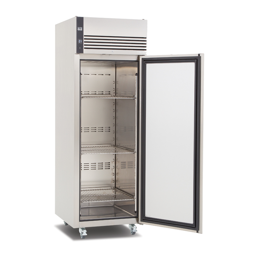
EcoPro G2 Range
Cabinet & Counter Models
FD1-11 & FD1-14 Controller
Reduced Width Counter Models
FD2-10 Controller & LCD5S Display
English
ISO 9001
Version 3
ISO 14001
By Appointment to
Her Majesty Queen Elizabeth II
Suppliers of Commercial Refrigeration
Foster Refrigerator, King's Lynn
A Division of ITW Ltd
Foster Refrigerator,
Oldmedow Road,
King's Lynn,
Norfolk, PE30 4JU
United Kingdom
Advertisement


Need help?
Do you have a question about the EcoPro G2 Series and is the answer not in the manual?
Questions and answers