Sign In
Upload
Download
Table of Contents
Contents
Add to my manuals
Delete from my manuals
Share
URL of this page:
HTML Link:
Bookmark this page
Add
Manual will be automatically added to "My Manuals"
Print this page
×
Bookmark added
×
Added to my manuals
Manuals
Brands
Igema Manuals
Transmitter
DLT2
Installation and operating instructions manual
Igema DLT2 Installation And Operating Instructions Manual
Continuous water level transmitter
Hide thumbs
1
2
Table Of Contents
3
4
5
6
7
8
9
10
11
12
13
14
15
16
17
18
19
20
21
22
23
24
page
of
24
Go
/
24
Contents
Table of Contents
Bookmarks
Table of Contents
Table of Contents
1 Important Safety Instructions
Symbols Used in These Instructions
Intended Use of the Device
Safety at Work
Safety Instructions for this Device
Exclusion of Liability
2 Contents of the Packaging
3 Proper Use
4 System Description
Function
Control Unit
Error Messages
5 Assembly and Installation
Installation Dimensions and Descriptions
Installation
Electrical Connection
Schematic Diagram
Assignment Plan Evaluator
Cable Evaluator - Probe
Connecting the Probe
Power Interface 4 Ma
6 Configuration Via Menu
Basics
Diagram
Numerical Entry
Password Input - Example
Programming of Min. and Max. Level
Programming of the Overfill Protection (DLT3)
7 Technical Data
Device Data
Maximum Ratings of Outputs
Data Plate
8 Fault Analysis and Rectification
9 Declaration of Conformity
Advertisement
Quick Links
1
Programming of Min. and Max. Level
2
Fault Analysis and Rectification
Download this manual
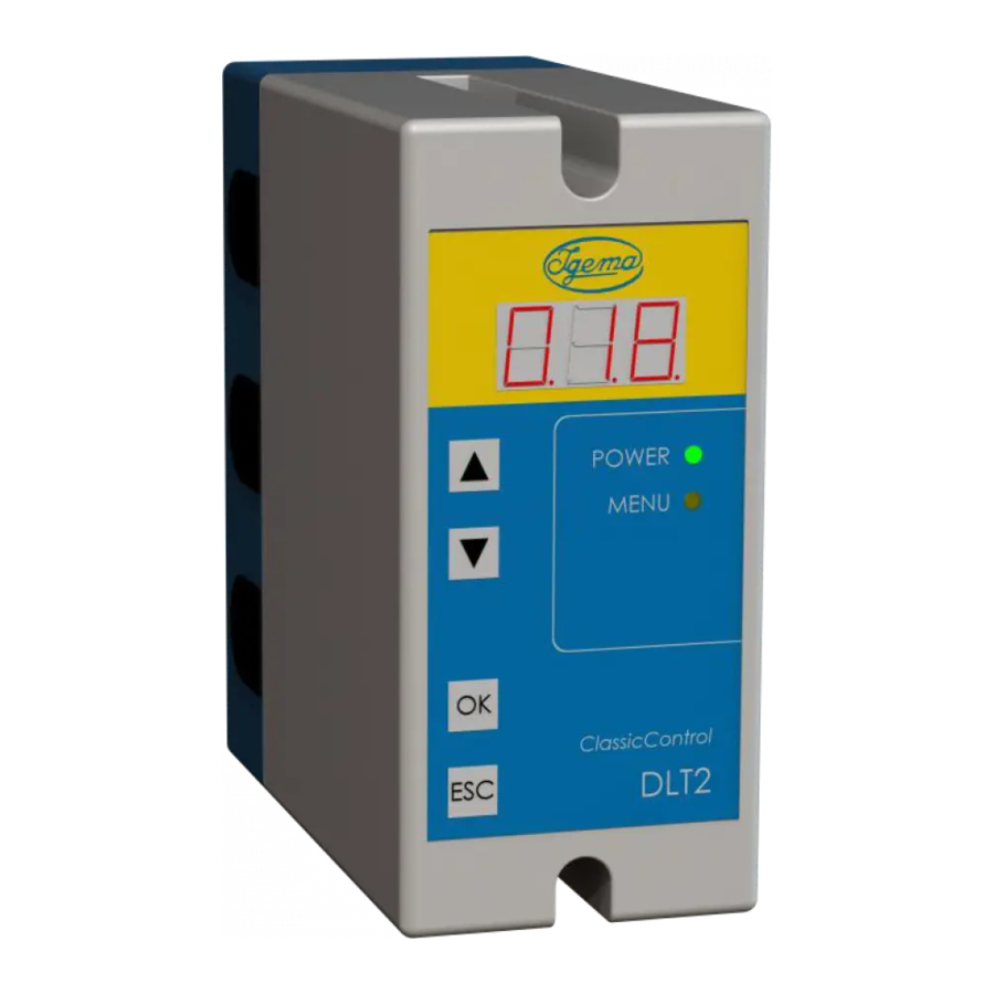
Continuous Water Level Transmitter
DLT2 / DLT3 with overfill protection
for use with the level probe: EC 8
Edition 11/2020
D-08-B-51053-EN-00
INSTALLATION- AND OPERATING INSTRUCTION
Table of
Contents
Previous
Page
Next
Page
1
2
3
4
5
Advertisement
Table of Contents
Need help?
Do you have a question about the DLT2 and is the answer not in the manual?
Ask a question
Questions and answers
Related Manuals for Igema DLT2
Transmitter Igema DLT3 Installation And Operating Instructions Manual
Continuous water level transmitter (24 pages)
This manual is also suitable for:
Dlt3
Classiccontrol dlt2
Classiccontrol dlt3
Table of Contents
Print
Rename the bookmark
Delete bookmark?
Delete from my manuals?
Login
Sign In
OR
Sign in with Facebook
Sign in with Google
Upload manual
Upload from disk
Upload from URL


Need help?
Do you have a question about the DLT2 and is the answer not in the manual?
Questions and answers