
Related Manuals for CombiSteel 7465.0055


Summary of Contents for CombiSteel 7465.0055
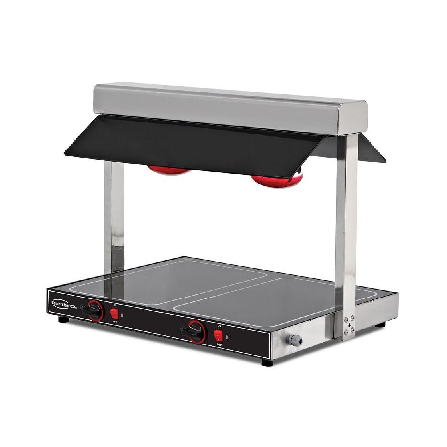
- Page 1 Hot Display Unit 7465.0055 – 7465.0060 User Manual Gebruikershandleiding Gebrauchsanweisung Le mode d’emploi...
-
Page 2: Table Of Contents
CONTENT ENGLISH GENERAL INFORMATION ..........................3 INSTALLATION..............................3 SAFETY INSTRUCTIONS........................... 4 OPERATION ..............................5 CLEANING & MAINTENANCE.......................... 5 TROUBLESHOOTING ............................6 SPARE PART LIST-EXPLODING DRAWING ......................7 ELECTRIC CIRCUIT SCHEMA ..........................8 NEDERLANDS ALGEMENE INFORMATIE ..........................10 INSTALLATIE ..............................11 VEILIGHEIDSINSTRUCTIES .......................... -
Page 3: Ageneral Information
Please demand original spare part. PRODUCT DESCRIPTION *The Professional Hot display unit, that provides high efficiency has been designed to be used in industrial kitchens. Product Code Dimensions (mm) Weight (kg) Packaging Dimensions (mm) 7465.0055 725x570x565 170x760x780 7465.0060 1040x570x565 170x1080x780 TECHNICAL INFORMATION Cable (mm²) -
Page 4: Binstallation
INSTALLATION *Please place the product to straight and sturdy ground, please take necessary steps against possibility of overturn. *Technician who will serve for installation and service for the appliance must be professional on this subject and must have installation and service licenses by the company. *Connection to Electric Power Supply must be done by authorized person. -
Page 5: Doperation
OPERATION * Control Panel : A : “ON” position B : “OFF” position : Thermostat button : Indicator lamp *Operating; • Plug in the appliance. • In order to operate the appliance switch to (ON) position. • When the appliance’s lamp is working , please check the light in the bottom side of it if it’s working also . •... -
Page 6: Troubleshooting
TROUBLESHOOTING Check if the appliance is plugged in. Check the electrical connections and voltage. THE APPLIANCE DOESN’T OPERATE 3. Check if the fuse is on or off. Check the thermostat button and heat setting. Check the resistance. THE APPLIANCE DOESN’T HEAT WELL 3. -
Page 7: Gspare Part List-Exploding Drawing
SPARE PART LIST-EXPLODING DRAWING 7465.0055 – 7465.0060 PRODUCT CODE: 7465.0055 PRODUCT NAME PRODUCT CODE BASE FRAME Y.EMP.STU.01.001 FEET Y.EMP.STU.01.002 WARNING LAMP Y.EMP.STU.01.003 THERMOSTAT BUTTON Y.EMP.STU.01.004 THERMOSTAT Y.EMP.STU.01.005 SWITCH (ON-OFF) Y.EMP.STU.01.006 MİCA Y.EMP.STU.01.007 SOCKET (E-27) Y.EMP.STU.01.008... -
Page 8: Helectric Circuit Schema
PRODUCT CODE: 7465.0060 PRODUCT NAME PRODUCT CODE BASE FRAME Y.EMP.STU.02.001 FEET Y.EMP.STU.02.002 WARNING LAMP Y.EMP.STU.02.003 THERMOSTAT BUTTON Y.EMP.STU.02.004 THERMOSTAT Y.EMP.STU.02.005 SWITCH (ON-OFF) Y.EMP.STU.02.006 MİCA Y.EMP.STU.02.007 SOCKET (E-27) Y.EMP.STU.02.008 LAMP Y.EMP.STU.02.009 GLASS RESISTANCE GROUP Y.EMP.STU.02.010 RESISTANCE Y.EMP.STU.02.011 ELECTRIC CIRCUIT SCHEMA 7465.0055... - Page 9 A1-A2 T1-T2 R1-R2 L1-L2 L3-L4 LARGE LIGHTED THERMOSTAT RESISTANCE THERMOSTAT OPEN INDICATOR UV LAMP 150W 0-1 SWITCH 30-90°C 500W LAMP 7465.0060 A1-A2-A3 T1-T2-T3 R1-R2-R3 L1-L2-L3 L4-L5-L6 LARGE LIGHTED THERMOSTAT RESISTANCE THERMOSTAT OPEN INDICATOR UV LAMP 150W 0-1 SWITCH 30-90°C 500W LAMP...
-
Page 10: Aalgemene Informatie
Zet het apparaat meteen uit bij een storing of defect. Het apparaat mag alleen door bevoegd servicepersoneel gerepareerd worden. Vraag om een origineel reserveonderdeel. PRODUCTOMSCHRIJVING *De Professionele Warmhoud unit, voor gebruik in bedrijfskeukens, zeer efficiënt Productcode Dimensies (mm) Gewicht (kg) Verpakkingsdimensies (mm) 7465.0055 725x570x565 170x760x780 7465.0060 1040x570x565 170x1080x780 TECHNISCHE INFORMATIE Kabel (mm²) -
Page 11: Binstallatie
INSTALLATIE *Zet het product op een vlakke en stevige ondergrond, neem de nodige maatregelen om te zorgen dat het niet valt. *Een technicus die helpt bij de installatie en het onderhoud van het apparaat moet professioneel zijn, en moet de nodige licenties voor installatie en service van het bedrijf verkregen hebben. *Verbinding met Elektrische Stroomvoorziening moet gemaakt worden door een bevoegd persoon. -
Page 12: Dbediening
BEDIENING * Controle paneel : A : “AAN” positie B : “UIT” positie Bediening: • Doe de stekker in het stopcontact. • Om het apparaat te gebruiken moet u het in de (AAN) positie zetten. • Als de lamp van het apparaat werkt , moet u kijken of de verlichting aan de onderkant ook werkt. •... -
Page 13: Troubleshooting
TROUBLESHOOTING Controleer of de stekker erin zit. Controleer de elektrische verbindingen en het HET APPARAAT WERKT NIET voltage. 3. Controleer of de zekering aan of uit is. Controleer de warmteknop en de instelling van de hitte. HET APPARAAT WORDT NIET GOED HEET Controleer de weerstand. -
Page 14: Glijst En Tekeningen Van Reserveonderdelen
LIJST EN TEKENINGEN VAN RESERVEONDERDELEN 7465.0055 – 7455.0060 PRODUCTCODE: 7465.0055 PRODUCTNAAM PRODUCTCODE BASISFRAME Y.EMP.STU.01.001 POOTJES Y.EMP.STU.01.002 WAARSCHUWINGSLAMP Y.EMP.STU.01.003 THERMOSTAAT KNOP Y.EMP.STU.01.004 THERMOSTAAT Y.EMP.STU.01.005 SCHAKELAAR (AAN-UIT) Y.EMP.STU.01.006 MİCA Y.EMP.STU.01.007 CONTACTDOOS (E-27) Y.EMP.STU.01.008 LAMP Y.EMP.STU.01.009... -
Page 15: Helectrisch Circuit Schema
GLAS WEERSTAND GROEP Y.EMP.STU.01.010 WEERSTAND Y.EMP.STU.01.011 PRODUCTCODE: 7465.0060 PRODUCTNAAM PRODUCTCODE BASISFRAME Y.EMP.STU.02.001 POOTJES Y.EMP.STU.02.002 WAARSCHUWINGSLAMP Y.EMP.STU.02.003 THERMOSTAAT KNOP Y.EMP.STU.02.004 THERMOSTAAT Y.EMP.STU.02.005 SCHAKELAAR (AAN-UIT) Y.EMP.STU.02.006 MİCA Y.EMP.STU.02.007 CONTACTDOOS (E-27) Y.EMP.STU.02.008 LAMP Y.EMP.STU.02.009 GLAS WEERSTAND GROEP Y.EMP.STU.02.010 WEERSTAND Y.EMP.STU.02.011 ELECTRISCH CIRCUIT SCHEMA 7465.0055... - Page 16 A1-A2 T1-T2 R1-R2 L1-L2 L3-L4 GROTE VERLICHTE THERMOSTAAT WEERSTAND UV LAMP THERMOSTAAT OPEN INDICATOR 0-1 SCHAKELAAR 30-90°C 500W 150W LAMP 7465.0060 A1-A2-A3 T1-T2-T3 R1-R2-R3 L1-L2-L3 L4-L5-L6 GROTE VERLICHTE THERMOSTAAT WEERSTAND UV LAMP THERMOSTAAT OPEN INDICATOR 0-1 SCHAKELAAR 30-90°C 500W 150W LAMP...
-
Page 17: Aallgemeine Empfehlung
Fragen sie nach Orginal-Ersatzteilen. BESCHREIBUNG *Diese Maschine ist speziell für den Einsatz in Groß-Küchen entwickelte und konztruierte Warmhaltevitrine. Code Mase (mm) Gewicht (kg) Verpackungsmase (mm) 7465.0055 725x570x565 170x760x780 7465.0060 1040x570x565 170x1080x780 TECHNISCHE INFORMATIONEN UV Glühbir. -
Page 18: Bmontage
MONTAGE *Stellen sie die Maschine auf eine harte und ebene Oberfläche um es vor Kipp- und Strurzgefahren zu schützen. *Nur die von uns registrierte und lizenzierte oder anerkannte Firmen und Personen dürfen die Geräte installieren und Kundendienst durchführen. *Der Stromanschluss muss von qualifiziertem und befugtem Personal durchgeführt werden. *Stellen sie sicher, das die Netzspannung der vom Hersteller angegebenen Betriebsspannung entspricht. -
Page 19: Anwenndung Der Maschine
ANWENNDUNG DER MASCHINE * Bedienungstafel : A : Gerӓt in Betrien “ON” B : Gerӓt au ẞ er Betrieb“OFF” : Thermostat Schalter : Anzeigeleuchte *Bedienung: • Den Stecker das Gerät anschließen. ON/OFF Schalter auf "ON" bringen. • Anzeigeleuchte des Gerӓtes wird leuchten. •... -
Page 20: Fehler Behebung
FEHLER BEHEBUNG Kontrollieren sie ob der Stecker der Maschine gesteckt ist. Überprüfen sie die Stromverbindung. GERӒT FUNKTIONIERT NICHT 3. Überprüfen Sie die Sicherung. Kontrollieren Thermostat Schalter Temperatur. ERREICHT GEWÜNSCHTE TEMPERATUR NICHT Kontrolliren Sie die Heizelemente. 3. Kontrollieren Sie den Glühbirne. 1. -
Page 21: Gersatzteile Demontage Liste
ERSATZTEILE DEMONTAGE LISTE 7465.0055 – 7465.0060 GERӒTE CODE: 7465.0055 TEILE BEZEICHNUNG TEILE CODE RAHMEN Y.EMP.STU.01.001 FUSS Y.EMP.STU.01.002 SIGNALLEUCHTE Y.EMP.STU.01.003 THERMOSTAT SCHALTER Y.EMP.STU.01.004 THERMOSTAT Y.EMP.STU.01.005 SCHALTER (ON-OFF) Y.EMP.STU.01.006 PLEXIGLAS Y.EMP.STU.01.007 SENSES (E-27) Y.EMP.STU.01.008 GLÜHBIRNE Y.EMP.STU.01.009... -
Page 22: Helektrischer Schaltplan
Y.EMP.STU.01.010 HEIZELEMENT Y.EMP.STU.01.011 GERӒTE CODE: 7465.0060 TEILE BEZEICHNUNG TEILE CODE RAHMEN Y.EMP.STU.02.001 FUSS Y.EMP.STU.02.002 SIGNALLEUCHTE Y.EMP.STU.02.003 THERMOSTAT SCHALTER Y.EMP.STU.02.004 THERMOSTAT Y.EMP.STU.02.005 SCHALTER (ON-OFF) Y.EMP.STU.02.006 PLEXIGLAS Y.EMP.STU.02.007 SENSES (E-27) Y.EMP.STU.02.008 GLÜHBIRNE Y.EMP.STU.02.009 GLAS HEIZELEMENT SATZ Y.EMP.STU.02.010 HEIZELEMENT Y.EMP.STU.02.011 ELEKTRISCHER SCHALTPLAN 7465.0055... - Page 23 A1-A2 T1-T2 R1-R2 L1-L2 L3-L4 Breit Thermostat Thermostat 30- Heizelement beleuchtete 0-1 Offen 90°C 500W Leuchte150W Schalter Signalleuchte 7465.0060 A1-A2-A3 T1-T2-T3 R1-R2-R3 L1-L2-L3 L4-L5-L6 Breit Thermostat Thermostat 30- Heizelement beleuchtete 0-1 Offen 90°C 500W Leuchte150W Schalter Signalleuchte...
-
Page 24: Ainformations Generales
être appeler. Le changement des pièces de rechange doit être original. DEFINITIONS * Pont chauffant infrarouge est produit pour être utilisé dans les cuisines industrielles. Code Dimensions (mm) Poids (kg) Dimensions d’emballage (mm) 7465.0055 725x570x565 170X760X780 7465.0060 1040x570x565 170X760X780 INFORMATION TECHNIQUE... -
Page 25: Installation
INSTALLATION Placez le produit sur une surface plane et stable, vous devez prendre les précautions nécessaires contre le risque de basculement. Pour l'installation le service vous donnera un expert agrée avec une obligation d'avoir une licence. La connexion à l'alimentation électrique, doit être effectuée par une personne autorisée. La connection de votre appareil, doit être faite selon les valeurs indiqué... -
Page 26: Dutilisation De L'appareil
UTILISATION DE L’APPAREIL * Paneau de controle : A : Bouton “START” B : Bouton “STOP” : Bouton du Thermostat : Lamp d‟indicateur Utilisation: • Insérez la fiche secteur de l'appareil. • Pour opérer l'appareil commutent (à „‟ON‟‟) la position. •... -
Page 27: Resolution Des Problemes
RESOLUTION DES PROBLEMES Vérifier si l'appareil est branché. Vérifier les connexions électriques et la tension. L'APPAREIL N'OPÈRE PAS 3. Vérifiez si le fusible est branché ou débranché. Vérifiez le bouton de thermostat et l'arrangement de chaleur. L'APPAREIL NE CHAUFFE PAS BIEN Vérifiez la résistance. -
Page 28: Gvoir La Liste Des Pieces De Rechange-Demonte
VOIR LA LISTE DES PIECES DE RECHANGE-DEMONTE 7465.0055 – 7465.0060 CODE: 7465.0055 NOM DE PRODUIT PRODUCT CODE CADRE DE BASE Y.EMP.STU.01.001 PIEDS Y.EMP.STU.01.002 AVERTISSEMENT DE LAMPE Y.EMP.STU.01.003 BOUTON DE THERMOSTAT Y.EMP.STU.01.004 THERMOSTAT Y.EMP.STU.01.005 COMMUTATEUR (MARCHE-ARRÊT) Y.EMP.STU.01.006 MICA Y.EMP.STU.01.007 PRISE ÉLECTRIQUE (E-27) Y.EMP.STU.01.008... -
Page 29: Hschema Du Circuit Electrique
CADRE DE BASE Y.EMP.STU.02.001 PIEDS Y.EMP.STU.02.002 AVERTISSEMENT DE LAMPE Y.EMP.STU.02.003 BOUTON DE THERMOSTAT Y.EMP.STU.02.004 THERMOSTAT Y.EMP.STU.02.005 COMMUTATEUR (MARCHE-ARRÊT) Y.EMP.STU.02.006 MICA Y.EMP.STU.02.007 PRISE ÉLECTRIQUE (E-27) Y.EMP.STU.02.008 LAMPE Y.EMP.STU.02.009 GROUPE DE RÉSISTANCE DE VERRE Y.EMP.STU.02.010 RÉSISTANCE Y.EMP.STU.02.011 SCHEMA DU CIRCUIT ELECTRIQUE 7465.0055... - Page 30 A1-A2 T1-T2 R1-R2 L1-L2 L3-L4 THERMOSTAT GRAND RESISTANCE LAMP LAMPE THERMOSTAT ALLUMÉ (0-1) D'INDICATEUR 30-90°C 500W 150W COMMUTATEUR OUVERTE 7465.0060 A1-A2 T1-T2 R1-R2 L1-L2 L3-L4 THERMOSTAT GRAND THERMOSTAT RESISTANCE LAMP LAMPE ALLUMÉ (0-1) D'INDICATEUR 30-90°C 500W 150W COMMUTATEUR OUVERTE...
Need help?
Do you have a question about the 7465.0055 and is the answer not in the manual?
Questions and answers