
Subscribe to Our Youtube Channel
Related Manuals for impact VC-500LR


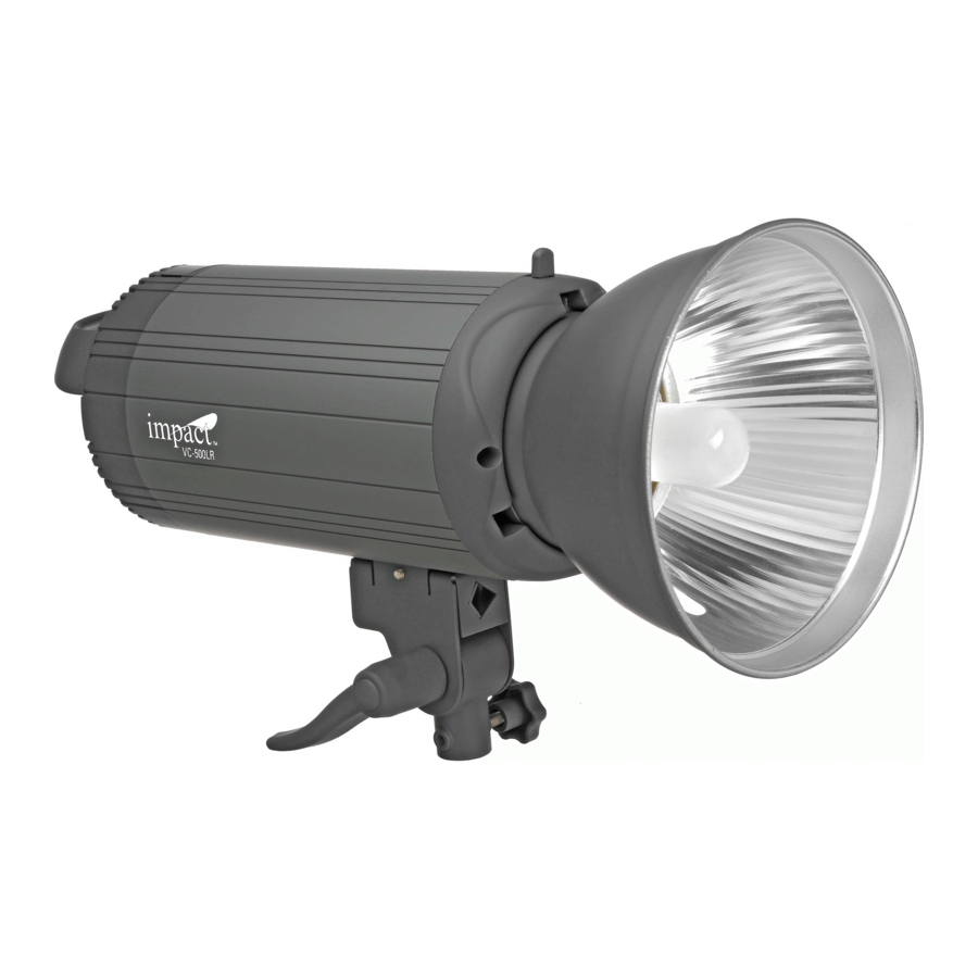
Summary of Contents for impact VC-500LR
- Page 1 VC-500LR Monolight VC-500LR Monolight INSTRUCTIONS INSTRUCTIONS...
-
Page 2: Warranty
We will not approve any artwork which has been a Warranty Congratulations on your purchase of the Impact VC-500LR Monolight. We feel that it will contribute much to your photographic skill and enjoyment. This light incorporates numerous advanced features, and was designed to provide many years of trouble-free service. - Page 3 EDIT OR REVISE ARTWORK prove any artwork which has been altered by the vendor Contents of carton Carefully remove the monolight from the box. You should have the following: Mount on a stand without re ector...
- Page 5 T – Umbrella Holder Power Supply Before plugging the power cord into the wall socket, make certain that the power switch is set to the OFF (“O” position). Note: The VC-500LR monolight is designed to work on 220V~240V 50Hz AC current. Power Switch Turn the power switch to the ON (“—“)
-
Page 6: Flash Settings
Flash Settings Flash Output The ash power output is variable over a ve Setting Power f/stop range (six f/stops) from full power to 1/32 power in 1/10 f/stop increments. The power is Full Power displayed on the LCD screen in decimal form. 1/2 Power The smaller top number represents the 1/4 Power... - Page 7 Modeling Lamp Settings Lamp Saving Technology The VC-500LR has built-in soft-start circuitry to ensure longer modeling lamp life. When the modelling lamp is turned on it will light up at a minimum brightness and slowly reach full brightness after a few seconds. This technology will allow the user to make fewer replacement lamp purchases over time.
- Page 8 The modeling light and ash icons will Modeling light and ash power are return, as will the words “MODEL” and controlled simultaneously. ”FLASH.“ The VC-500LR will retain your Audio beep is ON. settings after you power the unit off. Both increasing and decreasing the power settings generates heat inside the unit.
-
Page 9: Triggering The Flash
(more on that later). Sync Connection The sync jack on the VC-500LR may be used for direct connection to a camera set to ‘X’ synchronization. A radio slave receiver may also be plugged into this socket. - Page 10 Photocell Settings To Set the Photocell By repeatedly pressing the SLAVE MODEL button you can cycle through choices to FLASH set the photocell to trigger the ash after one, two or three ashes are FLASH detected. Or you can set the photocell READY to OFF.
-
Page 11: Audible Beep Settings
Audible Beep Settings A beep will sound once, when the ash is recycled and ready to flash. You can MODEL turn this audible beeper on and off by pressing the AUDIO button on the back FLASH panel. The musical notes symbol will FLASH display if the beeper is on, and will not READY... - Page 12 Firmly press the umbrella shaft through the holder. The locking knob is located on the side. Do not overtighten to avoid damaging the shaft of the umbrella. The re ector supplied with the VC-500LR features a slot through which you can feed the umbrella shaft. Softboxes Use of a heavy accessory such as a large softbox can make the ash unstable.
-
Page 13: Changing The Flash Tube
Changing the Flash Tube Discharge the Flash Unit The charge in the flash unit must be discharged before removing the flash tube. Make sure the flash unit is on. Push the TEST button on the rear panel of the flash. The unit will flash, discharging the power. -
Page 14: Changing The Fuse
Changing the Fuse A 6A fuse is mounted in the rear panel and protects the circuitry of the flash unit. Turn off the unit and disconnect the power supply before changing the fuse. Never replace with a fuse of a different type or rating. A spare 6A fuse is tted within the fuse holder. Use a small screwdriver to release the fuse cover. -
Page 15: Protection Features
Protection Features The VC-500LR is equipped with advanced overheating and overcharge warning and protection circuits to prevent damage to the internal electronics. Overheating Protection After a long shooting session at high output, the recycling time of the ash will increase automatically until the ash cools down to a safe level, and then will start working normally again. -
Page 16: Error Codes
Error Codes In the event of a malfunction, the LCD screen will display a blinking error code. The WARNING icon will also blink. In addition, errors codes E2 and E3 have a beep warning. Following is a short description of the three error codes and the necessary action to take. MODEL FLASH WARN... - Page 17 Safety Notes...
- Page 18 DO NOT EDIT OR REVISE We will not approve any artwork which has been a Contents of carton Carefully remove the monoligh WARD PROOFS bhphotovideo.com PROVAL E FINAL UCTION Mount on a stand N PRODUCTION without re ector OR APPROVAL ROOFS...
- Page 19 This d was designed to provide ese operating instructions Impact provides a limited warranty that this product is free from defects in materials and his equipment. Impact’s responsibility with respect to this limited warranty shall be limited solely to repair or replacement, at its option, of any product which fails during normal consumer use.
- Page 20 To see all of our lighting equipment, please visit our website. impact www.impactstudiolighting.com...
Need help?
Do you have a question about the VC-500LR and is the answer not in the manual?
Questions and answers