Table of Contents
Advertisement
Quick Links
Advertisement
Table of Contents

Subscribe to Our Youtube Channel
Related Manuals for Chipsee CS12102F170P-C111


Summary of Contents for Chipsee CS12102F170P-C111
- Page 1 PPC-A9-170-C User Manual Release 2.0 www.chipsee.com...
- Page 2 Chipsee Products Naming Rules CS12102F170P-C111 Chipsee Product Abbreviations www.chipsee.com...
- Page 3 Horizontal Resolution Means 800 Pixel Means 1024 Pixel Means 1280 Pixel Means 1440 Pixel Means 1920 Pixel Vertical Resolution Means 480 Pixel Means 600 Pixel Means 768 Pixel Means 800 Pixel Means 900 Pixel Means 1024 Pixel Means 1080 Pixel...
-
Page 4: Hardware Features
Means Embedded PC or Panel PC Means Embedded PC without Case Means Panel PC with Case Means Touch Type Means Resistive Touch Means Capacitive Touch Means LCD Brightness Means Common Brightness Means High Brightness PCB Version Baseboard PCB Version Number... - Page 5 1 Channel 1000M LAN 3.5mm Audio In/Out Connector, 2W Speaker Audio Internal Buzzer RS232 4 Channels RS485 Optional Optional WiFi/BT On-Board WIFI/BT HDMI 1 Channel SATA II 1 Channel 4G/LTE Optional Power Input 15~36V DC Current @ 15V 2000 mA max...
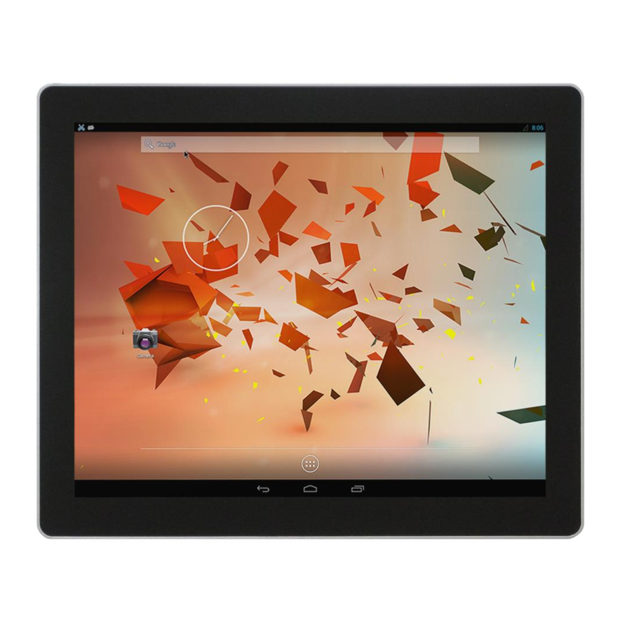
- Page 6 CS12102F170P- C111 Figure 1: Front View (Android) www.chipsee.com...
-
Page 7: Power Input Connector
Figure 2: Back View Power Input Connector The product CS12102F170P-C111 uses a wide-range power input 15~36V. The total power consumption is normally about 20W. The Power Input Connector is 3 Pin 3.81mm Screw Terminal Connector as Figure 3 shows. - Page 8 A detailed description of the power input connector pins is provided in Table 1. Figure 3: Power Input Connector Table 1 Power Input Pin Definition: Pin Number Definition Description Connect to DC Power Positive Pin 1 Positive Input Terminal...
- Page 9 Pin 3 is connected to Ground. This method can eliminate the problem totally. You can test it by touching the GND of CS12102F170P-C111 with one hand, while the other hand operates on the capacitive touch screen. In this case, the user’s body acts as the Power System Ground.
-
Page 10: Usb Host Connector
500mA. Figure 5: USB HOST Connector USB OTG Connector The product CS12102F170P-C111 has one USB OTG connector, shown in Figure 6, that works as a slave by default. It can be used to establish a connection with the host PC. -
Page 11: Lan Connector
Figure 6: USB OTG Connector LAN Connector The product CS12102F170P-C111 has one channel 1000Mbit Ethernet Connector, as Figure 7 shows. Figure 7: LAN Connector Audio Connector There is one Audio Input (“Line-in”) and one Audio Output (“Line-out”), as Figure 8 shows. As well as an internal 2W speaker. -
Page 12: Hdmi Connector
The TF card slot doesn’t come with a TF card by default. WiFi+BT The product CS12102F170P-C111 has one WiFi+BT. It uses Realtech RTL8723 which integrates WiFi and BT. There is a connector on the backside case that is used to connect the external WiFi/BT Antenna, as Figure 9 shows. -
Page 13: Boot Switch
The product CS12102F170P-C111 has one HDMI connector as shown in Figure 10. The HDMI output resolution can be configured by software. Figure 10: HDMI Connector Boot Switch The product CS12102F170P-C111 has a boot switch, shown in Figure 11, used to change the boot sequence. For more details on the boot switch configuration, please refer to Table 2. -
Page 14: Expansion Connector
Table 2 Boot Config Select: Mode TF Card eMMC Download Expansion Connector T h e p r o d u c t C S 1 2 1 0 2 F 1 7 0 P - C 1 1 1... -
Page 15: Dimensions And Mounting
Dimensions The dimensions of CS12102F170P-C111 are 392*330*62mm. Mounting Method This product CS12102F170P-C111 can be mounted by VESA mounting method (100x100cm or 75x75cm), as Figure 13 shows. Please make sure the display is not exposed to high pressure when mounting into an enclosure. -
Page 16: How To Get Support
Figure 13: Mounting Method How to Get Support Please feel free to contact us with any questions, queries or suggestions. If your question is about technical support or troubleshooting for one of our products, we kindly ask you to first check our documentation for a possible solution. - Page 17 If you cannot find the solution you are looking for then please write to contact@chipsee.com providing all possible details. www.chipsee.com...
Need help?
Do you have a question about the CS12102F170P-C111 and is the answer not in the manual?
Questions and answers