
Related Manuals for Rohde & Schwarz R&S TS-PCA3


Summary of Contents for Rohde & Schwarz R&S TS-PCA3
- Page 1 ® R&S TS-PCA3 Test System Versatile Platform ® R&S CompactTSVP User Manual (;ÂW8<) 1152390812 Version 19...
- Page 2 ® This manual describes the following R&S TSVP models: ● ® R&S TS-PCA3 (1152.2518.02) © 2021 Rohde & Schwarz GmbH & Co. KG Mühldorfstr. 15, 81671 München, Germany Phone: +49 89 41 29 - 0 Email: info@rohde-schwarz.com Internet: www.rohde-schwarz.com Subject to change – data without tolerance limits is not binding. R&S ®...
- Page 3 Safety Instructions Instrucciones de seguridad Sicherheitshinweise Consignes de sécurité Risk of injury and instrument damage The instrument must be used in an appropriate manner to prevent personal injury or instrument damage. ● Do not open the instrument casing. ● Read and observe the "Basic Safety Instructions" delivered as printed brochure with the instrument.
- Page 4 Gefahr von Verletzungen und Schäden am Gerät Betreiben Sie das Gerät immer ordnungsgemäß, um elektrischen Schlag, Brand, Verletzungen von Personen oder Geräteschäden zu verhindern. ● Öffnen Sie das Gerätegehäuse nicht. ● Lesen und beachten Sie die "Grundlegenden Sicherheitshinweise", die als gedruckte Broschüre dem Gerät beiliegen. ●...
-
Page 5: Table Of Contents
® Contents R&S TS-PCA3 Contents 1 User Information..................9 Foreword........................9 Related Documentation....................9 Purpose of the User Manual..................9 Explanation of Symbols..................... 10 2 Safety....................12 General.........................12 Safety Instructions......................13 3 Description................... 14 Usage........................... 14 3.1.1 General......................... 14 3.1.2 Explanation of Terms.....................14 3.1.3 System Information....................... - Page 6 ® Contents R&S TS-PCA3 3.3.11 Cooling.......................... 32 3.3.12 Option R&S TS-PK04....................32 System Module R&S TS-PSYS1.................33 3.4.1 General......................... 33 3.4.2 Characteristics......................33 3.4.3 Circuit Diagram of the R&S TS-PSYS1.................33 3.4.4 Structure of the R&S TS-PSYS1...................34 3.4.5 Functional Description of the R&S TS-PSYS1..............36 3.4.5.1 Control...........................36 3.4.5.2...
- Page 7 ® Contents R&S TS-PCA3 4.4.3 Connections at the Front....................47 Cabling......................... 47 4.5.1 Concept.........................47 4.5.2 Analog Bus........................49 4.5.3 PXI Trigger Bus......................49 4.5.4 Internal Cabling of Short cPCI Modules................ 49 4.5.5 External Cabling......................50 4.5.6 Opening the Case......................51 5 Operation....................53 General.........................53 Powering the Unit ON and OFF..................53 Self-Test........................
- Page 8 ® Contents R&S TS-PCA3 8.1.5 Fan Connectors X90, X91, X92, X93................68 8.1.6 Expansion Connector X80.................... 68 8.1.7 Jumper Field......................... 69 8.1.8 IPMB0........................... 69 Analog Bus Backplane....................69 8.2.1 Position of Interfaces.....................69 8.2.2 Analog Bus Connectors X1 ... X16................70 8.2.3 Analog Bus Connector X21...................70 8.2.4 Analog Bus Connector X22...................71...
- Page 9 ® Contents R&S TS-PCA3 A Appendix....................84 R&S TS-PCA3 Backplane Versions................84 A.1.1 Effects of the R&S TS-PCA3 backplane redesign............84 A.1.2 Effects of the TS-PCA3 backplane redesign V4.0............84 A.1.2.1 Reason..........................84 A.1.2.2 Steps taken........................85 A.1.2.3 Effects........................... 85 A.1.3 Effects of the versions on individual modules............... 86 A.1.3.1 Can be used in slots 5 to 14 without any restrictions............
- Page 10 ® Contents R&S TS-PCA3 User Manual 1152.3908.12 ─ 19...
-
Page 11: User Information
® User Information R&S TS-PCA3 Purpose of the User Manual 1 User Information 1.1 Foreword We congratulate you on your purchase of a ROHDE & SCHWARZ Test System Versa- tile Platform R&S TS-PCA3. We would emphasize that only attendance at one of our regular inhouse training semi- nars can ensure your successful operation of the Test System Versatile Platform in the long term. -
Page 12: Explanation Of Symbols
® User Information R&S TS-PCA3 Explanation of Symbols As well as the operating instructions and the health and safety instructions which apply at the site where the system is used, the applicable technical standards and regula- tions for safe and proper working must be complied with. The operating instructions must be available at or near the R&S TS-PCA3 at all times. - Page 13 ® User Information R&S TS-PCA3 Explanation of Symbols Highlights important details to which special attention must be paid and that make work easier. User Manual 1152.3908.12 ─ 19...
-
Page 14: Safety
® Safety R&S TS-PCA3 General 2 Safety 2.1 General The Test System Versatile Platform must be operated in accordance with the safety regulations which apply in the owner's country. Safety risks created by an application that is based on the Test System Versatile Plat- form must be eliminated by suitable additional arrangements (e.g. -
Page 15: Safety Instructions
® Safety R&S TS-PCA3 Safety Instructions 2.2 Safety Instructions ELECTROCUTION HAZARD! Before opening the case, the Test System Versatile Platform must be powered off and isolated from the power supply! The Test System Versatile Platform may only be opened by skilled person! Also the rear side modules may only be exchanged by skilled person. -
Page 16: Description
® Description R&S TS-PCA3 Usage 3 Description 3.1 Usage 3.1.1 General The Produktionstestplattform R&S TS-PCA3 is a standardized modular platform for the program-controlled testing of modules and terminals in the factory or laboratory. With its flexible configuration and the use of worldwide standards, it can be perfectly adapted to suit the needs of the user. -
Page 17: System Information
® Description R&S TS-PCA3 Usage PXI (PCI eXtensions for Instrumentation) is a standard defined by National Instruments which expands the CompactPCI, using its mechanical specifications and the connec- tion with the system controller. The PXI standard is fully compatible and also defines a number of additional signals which are useful for measuring applications, such as the PXI Triggerbus. - Page 18 ® Description R&S TS-PCA3 Usage Figure 3-1: Configuration of the R&S TS-PCA3 Starting with backplane version V4.x, some changes have been made to details to avoid incompatibilities with some third-party modules. The effects on the configurability of modules are described in Chapter 7.2, "Configuration Instructions", on page 57.
-
Page 19: Views
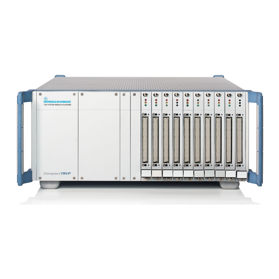
® Description R&S TS-PCA3 Views Other Characteristics Optional: Front mounted adapter interface on the R&S TS-PCA3 that uses spring contacts to facilitate rapid and high-pole contacting with the test devices (see Figure 3-4 System serviceability is monitored by a built-in self-test capability and system monitor (operating voltages, temperature) 3.2 Views Figure 3-2... -
Page 20: Construction
® Description R&S TS-PCA3 Construction Figure 3-4: Adapter Interface 3.3 Construction 3.3.1 Case The R&S TS-PCA3 uses the standard ROHDE & SCHWARZ case of the “Design 2000”. Figure 3-5: BW 2000 Case User Manual 1152.3908.12 ─ 19... - Page 21 ® Description R&S TS-PCA3 Construction Table 3-3: Features of the BW 2000 Case HF-immune case to Rohde & Schwarz “Design 2000” Dimensions: 19", height 4U, 430 mm deep Use as desktop unit or rack-mounted case Mounted in 19" rack using the telescopic slide set or on support rails Side case handles that remain on the unit when mounted in the rack.
-
Page 22: Slot Layout
® Description R&S TS-PCA3 Construction 3.3.2 Slot Layout 3.3.2.1 Plan View Figure 3-6: Plan View (Example) User Manual 1152.3908.12 ─ 19... -
Page 23: Side View
® Description R&S TS-PCA3 Construction 3.3.2.2 Side View Figure 3-7: Side View 3.3.3 Backplanes The R&S TS-PCA3 contains the following backplanes: ● cPCI backplane with PICMG Power Interface and Rear I/O support ● Analog bus backplane ● Power backplane with PICMG Power Interface (optional) Figure 3-8shows the backplanes with the bus systems. - Page 24 ® Description R&S TS-PCA3 Construction ● 72 HP ● 32 bit ● 33 MHz ● = 5 V The backplane fulfils the Hot-Swap capability according to Standard PICMG 2.1 Rev. 2.0 for the exchange of measuring and control cards during operation. The 32 bit area conforms to PICMG 2.0 Rev.
- Page 25 ® Description R&S TS-PCA3 Construction Table 3-4: CAN Bus Number Lines (VDC) CAN_H: P20/C1 CAN_L: P20/D1 In the old design V1.0 - V3.0, the CAN bus is bussed directly, guided via PXI local bus lines LBL10 and LBL11. In the most unfavorable case, this resulted in conflicts with other PXI modules that were using the lines in a different way.
- Page 26 ® Description R&S TS-PCA3 Construction signal sources. This can be used to provide a primary voltage to generate local supply voltages (DC/DC converter), etc. Table 3-5: External Additional Signals Number / Slot (ADC) Lines (VDC) Input for ext. signals: J20: AUX1 B20, E19 J20: AUX2 A20, D19 +5-V and +12-V lines from the P47 connector are routed on the screw bolts above slot 4.
-
Page 27: Analog Bus Backplane
® Description R&S TS-PCA3 Construction Figure 3-12: Connecting the current rail to AUX signals 3.3.3.2 Analog Bus Backplane To simplify cabling, the R&S TS-PCA3 contains an analog bus with 8 signals. The ana- log bus backplane is located in the front above the cPCI backplane. A special layout meets the need for high crosstalk damping and low capacitance of the signal lines to GND. - Page 28 ® Description R&S TS-PCA3 Construction The analog bus can be used flexibly with the ROHDE & SCHWARZ- specific plug-in modules. 8 equivalent lines are basically available (ABa1, ABa2, ABb1, ABb2, ABc1, ABc2, ABd1, ABd2). External instruments are usually connected to the R&S TS-PCA3 with a rear I/O connection.
-
Page 29: Power Backplane
® Description R&S TS-PCA3 Construction 3.3.3.3 Power Backplane The use of a second cPCI PSU in slots A1, A2 requires the optional Power Backplane (conforms to standard PICMG 2.0). From the Power Backplane, a cable with three con- nectors leads to a 24-pin ATX connector on the cPCI backplane. The three connectors are as follows (see also Chapter 8, "Interface Description",... -
Page 30: Geographical Addressing Of The Slots With Ga0
® Description R&S TS-PCA3 Construction The optional power backplane is supplied with AC voltage parallel to the cPCI back- plane. The PE conductor must be bonded to the case with a grounding cable. The GND signal of the analog bus backplane is connected by a cable and screw termi- nal to the GND on the cPCI backplane. -
Page 31: Can Bus
® Description R&S TS-PCA3 Construction Slot Code 0001 0010 0011 0100 0101 0110 0111 1000 1001 1010 1011 1100 1101 1110 1111 Note: 0: Pin connected to GND via resistor 1: Pin open 3.3.6 CAN Bus For controlling of some R&S modules, the CAN bus is used in TS-PCA3 and TS- PWA3. -
Page 32: Configurations With Several Frames Or Option R&S Ts-Pxb2
® Description R&S TS-PCA3 Construction Example: CAN0::0::5::15 Board Number: 0 Controller Number: 0 Device Number: 5 (Device 1, Rear-I/O) Slot Number: 15 The following table shows the jumper configuration for the bus terminations CAN1 (System) und CAN2 (User). Table 3-6: CAN Bus Termination Modul CAN-Bus open... -
Page 33: Switching The Psu
® Description R&S TS-PCA3 Construction Table 3-7: Device Addressing TS-PWA3 J1 (GA4) J2 (GA5) Device not set not set not set not set The optional R&S TS-PXB2 backplane extension also uses the CAN bus. For the mod- ules plugged there (only R&S TS-PIO3B or R&S TS-PTR permitted), GA4 and GA5 can also be configured via jumpers. -
Page 34: Line Connection And Power Switch
® Description R&S TS-PCA3 Construction 3.3.10 Line Connection and Power Switch The line inlet and power switch are at the back of the CompactTSVP (see Figure 3-3). 3.3.11 Cooling The R&S TS-PCA3 features a powerful cooling concept. The slots at the front (optional in the Rear I/O area) are cooled by a vertical flow of air. The four fans are located above the slots and are connected by inline contact connec- tors to the backplane. - Page 35 ® Description R&S TS-PCA3 System Module R&S TS-PSYS1 With installed option R&S TS-PK04, the switch modules R&S TS-PMB and TS-PSM2 cannot be operated in slot 16. 3.4 System Module R&S TS-PSYS1 3.4.1 General The R&S TS-PSYS1 is in the Rear I/O slot 15 of the R&S TS-PCA3. System functions such as voltage and temperature monitoring, switchable trigger sig- nals and optocoupler interface are used to integrate the CompactTSVP and Pow- erTSVP in a complete system.
- Page 36 ® Description R&S TS-PCA3 System Module R&S TS-PSYS1 Figure 3-18: Circuit Diagram of the R&S TS-PSYS1 3.4.4 Structure of the R&S TS-PSYS1 The R&S TS-PSYS1 is the size of a standard cPCI-RTM (Rear Transmission Module) and is mounted in slot 15 at the rear of the TSVP chassis. Connectors X1 and X20 are used to make the connections to the Rear I/O side of the cPCI backplane in the R&S TS-PCA3.
- Page 37 ® Description R&S TS-PCA3 System Module R&S TS-PSYS1 Figure 3-19: Connectors and Jumpers on the R&S TS-PSYS1 1152.4004.02 User Manual 1152.3908.12 ─ 19...
- Page 38 ® Description R&S TS-PCA3 System Module R&S TS-PSYS1 Figure 3-20: Jumper R&S TS-PSYS1 1157.9910.10 Table 3-10: Connectors on the R&S TS-PSYS1 Symbol cPCI Rear I/O (P1) cPCI Rear I/O (P2) Front Connector Jumper field Rear I/O signals 3.4.5 Functional Description of the R&S TS-PSYS1 (see also Figure 3-18)
- Page 39 ® Description R&S TS-PCA3 System Module R&S TS-PSYS1 ● 8 x enable of PXI trigger signals to the outside (e.g. PowerTSVP) ● 4 x optocoupler outputs (for PLC or handling systems) ● 4 x optocoupler inputs (for PLC or handling systems) ●...
- Page 40 ® Description R&S TS-PCA3 System Module R&S TS-PSYS1 portional analog voltage is also output at connector X30 for monitoring purposes (TEMP_OUT). Geographical Addressing Each slot is assigned its own digital slot code (GA code). This code is used internally to directly address the µC.
- Page 41 ® Description R&S TS-PCA3 Permitted Module Configuration In addition, with the jumpers on X40, the lines can be brought to the front-module R&S TS-PMB in the slot 15, see Chapter 8, "Interface Description", on page 58. The User CAN Controller can be operated via the RSCAN SW module. 3.4.6 Driver Software The local microcontroller is triggered by the CAN1 bus and the R&S-specific protocol.
- Page 42 ® Description R&S TS-PCA3 Permitted Module Configuration Figure 3-21: Module Configuration TS-PCA3 (Backplane Version 2.1 and 3.x) User Manual 1152.3908.12 ─ 19...
- Page 43 ® Description R&S TS-PCA3 Permitted Module Configuration Figure 3-22: Module Configuration TS-PCA3 The effects of the R&S TS-PCA3 backplane redesign V4.0 are described in Chap- ter A.1, "R&S TS-PCA3 Backplane Versions", on page 84. User Manual 1152.3908.12 ─ 19...
- Page 44 ® Commissioning R&S TS-PCA3 Setting Up 4 Commissioning 4.1 Safety Instructions When commissioning the Test System Versatile Platform R&S TS-PCA3 the safety instructions in Chapter 2, "Safety", on page 12 must be followed. 4.2 Setting Up 4.2.1 Requirements for Repeatable Measurements The ambient conditions listed below are recommended for the installation site of a Test System Versatile Platform with R&S TS-PCA3: ●...
- Page 45 ® Commissioning R&S TS-PCA3 Setting Up Note: Do not unscrew the rear four feet as this will loosen the body of the case! 4. Affix the self-adhesive plastic slide rails. 5. Place the unit into the rack on prepared aluminum rails. 6.
- Page 46 ® Commissioning R&S TS-PCA3 Installation 4.3 Installation 4.3.1 Safety Instructions Risk of electrostatic discharge (ESD) Electrostatic discharge (ESD) can cause damage to the electronic components of the instrument and the device under test (DUT). ESD is most likely to occur when you con- nect or disconnect a DUT or test fixture to the instrument's test ports.
- Page 47 ® Commissioning R&S TS-PCA3 Installation ● Run down and power off the R&S TS-PCA3. ● Select a suitable slot (see Chapter 4.3.2, "Compatibility", on page 44). ● Remove the appropriate front panel by slackening off the screws. Damaged backplane due to bent pins Bent pins may result in permanent damage to the backplane.
- Page 48 ® Commissioning R&S TS-PCA3 Connections 4.4 Connections 4.4.1 Line Inlet The R&S TS-PCA3 requires a supply within the range of 110 VAC / 60 Hz or 230 VAC / 50 Hz. Fuse protection for the line inlet must not exceed a rating of 16 A. The PSU used in the R&S TS-PCA3 has automatic voltage selection between 100 and 240 Volt AC (see Section 9, Technical Data).
- Page 49 ® Commissioning R&S TS-PCA3 Cabling 4.4.3 Connections at the Front Figure 4-2: Front Connections 1 = Slot (16) The Produktionstestplattform R&S TS-PCA3 has no connections in its basic configura- tion. The existing slots can be fitted with system and user-specific plug-in modules and connections.
- Page 50 ® Commissioning R&S TS-PCA3 Cabling ● External cabling: Cabling outside the case. Figure 4-3: Inner and Internal Cabling Variants 1 = Cabling of short cPCI modules to the adapter interface 2 = Cabling of short cPCI modules to the analog bus 3 = Analog bus 4 = Cabling of short cPCI modules to rear connectors 5 = Cabling analog bus to rear connectors...
- Page 51 ® Commissioning R&S TS-PCA3 Cabling ● System-specific connectors (e.g. D-sub) can be installed at the rear, from where signals are connected to the analog bus or the adapter interface. HF signals can also be carried in this way because there is ample space for suitable connectors. 4.5.2 Analog Bus The analog bus is available at all slots of the R&S TS-PCA3 with its own backplane.
- Page 52 ® Commissioning R&S TS-PCA3 Cabling Figure 4-4: Adaption of a Short PXI Module to the Adapter Interface (Example) 4.5.5 External Cabling External cabling is used to connect measuring and stimuli devices as well as the UUT to the R&S TS-PCA3. Implementing the following concept should ensure the clarity of external cabling design: ●...
- Page 53 ® Commissioning R&S TS-PCA3 Cabling 4.5.6 Opening the Case ELECTROCUTION HAZARD! Before opening the case, the R&S TS-PCA3 must be powered off and isolated from the power supply! The case of the Test System Versatile Platform R&S TS-PCA3 should only be opened by qualified engineers! The ESD (electrostatic discharge) regulations must be complied with when opening the case of the R&S TS-PCA3.
- Page 54 ® Commissioning R&S TS-PCA3 Cabling The R&S TS-PCA3 is now accessible from all sides. The case is closed in reverse order of opening. User Manual 1152.3908.12 ─ 19...
- Page 55 ® Operation R&S TS-PCA3 Instrument Soft Panels 5 Operation 5.1 General The R&S TS-PCA3 does not have any controls - all operation is performed by the soft- ware. Please refer to the appropriate documentation for details of software operation. 5.2 Powering the Unit ON and OFF The R&S TS-PCA3 is powered on and off with the power switch at the rear.
- Page 56 ® Maintenance R&S TS-PCA3 Cleaning 6 Maintenance 6.1 Important User Information The Test System Versatile Platform R&S TS-PCA3 is maintenance free. 6.2 Cleaning Elctrocution Hazard! The R&S TS-PCA3 must powered down before starting with cleaning the device. The following equipment and materials are recommended for cleaning the Test System Versatile Platform R&S TS-PCA3: ●...
- Page 57 ® Maintenance R&S TS-PCA3 Fuse Replacement 6.3 Fuse Replacement The power supply to the R&S TS-PCA3 is protected by fuses. These are located in the built-in plug at the rear of the R&S TS-PCA3. Figure 6-1: R&S TS-PCA3 Rear View 1 = Built-in plug with fuses (2 x IEC 127-T6.3H/250V) A blown fuse is replaced as follows: 1.
- Page 58 ® Plug-In Modules R&S TS-PCA3 General 7 Plug-In Modules 7.1 General The R&S TS-PCA3 is suitable for a wide range of plug-in modules based on the Com- pactPCI and PXI standards. The concept also meets the particular demands made on a modern production test platform.
- Page 59 ® Plug-In Modules R&S TS-PCA3 Configuration Instructions Round cable insert C42334-Z61-C16 96-way connector block, type R V42254-B1240-R960 (WireWrap pins) Other suppliers include Harting (shells and connectors), Erni and Panduit (connectors only). With adapters, remember that the count sequence at connectors P1 and P20 on the back of the cPCI backplane is the mirror image of the front.
- Page 60 ® Interface Description R&S TS-PCA3 c-PCI-Backplane 8 Interface Description 8.1 c-PCI-Backplane 8.1.1 Position of Interfaces Figure 8-1: cPCI Backplane (Front View) Figure 8-2: Connectors P1 and P20 Front (Mating Side) User Manual 1152.3908.12 ─ 19...
- Page 61 ® Interface Description R&S TS-PCA3 c-PCI-Backplane Figure 8-3: cPCI Backplane (Rear View) Figure 8-4: Connectors P1 and P20 Rear (Mating Side) Note: The count sequence is the mirror image of the front. 8.1.2 cPCI Connectors 8.1.2.1 General The following tables for the P20 connectors give two signal names for some signals. The right hand column indicates the R&S signal assignment.
- Page 62 ® Interface Description R&S TS-PCA3 c-PCI-Backplane 8.1.2.2 Slot 1 (System) BPIO = Backpanel I/O compatible with 32 bit cPCI CPU's Figure 8-5: Backplane version 4.0 8.1.2.3 Slot 3 and 4 (cPCI peripheral) NP = not populated, BP(I/O) = Backpanel I/O User Manual 1152.3908.12 ─...
- Page 63 ® Interface Description R&S TS-PCA3 c-PCI-Backplane Figure 8-6: Assignment Slot 3 and 4 * Backplane V2.x and 3.x: = BPIO * Backplane starting with = SWCAN_H_I and SWCAN_L_I (pins C1 and D1) act like BP(I/O) when V4.0: turned off; The CAN bus is turned on with CAN_EN_I via pull-up. CAN_EN_I is normally on GND or remains open.
- Page 64 ® Interface Description R&S TS-PCA3 c-PCI-Backplane Figure 8-7: Assignment Slot 5 ... 14 (Backplane Version 2.0 to 3.X) * Change starting with Backplane Version 2.1: ±12 V and +5 V on front removed, isolated User Manual 1152.3908.12 ─ 19...
- Page 65 ® Interface Description R&S TS-PCA3 c-PCI-Backplane Figure 8-8: Assignment Slot 5 ... 14 (Backplane Version 4.X) 8.1.2.5 Slot 15 (PXI peripheral / Rear I/O for TS-PSYS) NC = not connected, NP = not populated, BPIO = Backpanel I/O All signals are output at the back. REQ7#, GNT7# and CLK7 additionally routed to P1 and used by TS-PSYS1. AD21 is used by TS-PSYS1 as IDSEL.
- Page 66 ® Interface Description R&S TS-PCA3 c-PCI-Backplane Figure 8-9: Assignment Slot 15 (Backplane Version 2.0 to 3.X) * Change starting with Backplane Version 2.1: ±12 V and +5 V on front removed, isolated User Manual 1152.3908.12 ─ 19...
- Page 67 ® Interface Description R&S TS-PCA3 c-PCI-Backplane Figure 8-10: Assignment Slot 15 (Backplane Version 4.X) 8.1.2.6 Slot 16 (CAN) NC = not connected, NP = not populated, BPIO = Backpanel I/O User Manual 1152.3908.12 ─ 19...
- Page 68 ® Interface Description R&S TS-PCA3 c-PCI-Backplane Figure 8-11: Assignment Slot 16 8.1.3 Connector X0 (P47) Figure 8-12: Connector X0 (P47) Table 8-1: Assignment X0 (P47) Signal Name Description V1 Output 5-12 V1 and V2 Return 13-18 V2 Output V3 Return V3 Output V4 Output Signal Return...
- Page 69 ® Interface Description R&S TS-PCA3 c-PCI-Backplane Signal Name Description Reserved Reserved Enable Reserved Not connected V1SENSE V1 Remote Sense Reserved Not connected V2SENSE V2 Remote Sense S RTN Sense Return V1SHARE V1 Current Share V3SENSE V3 Remote Sense Reserved DEG# Degrade Signal INH# Inhibit...
- Page 70 ® Interface Description R&S TS-PCA3 c-PCI-Backplane Signal Signal FAL- V1 Current Share PW-OK PRST- GND Sense +5 V +5 V PS-ON +3.3 V -12 V +3.3 V +3.3 V 8.1.5 Fan Connectors X90, X91, X92, X93 Table 8-3: Assignment of X90 ... X93 Signal FANCTRL +12 V...
- Page 71 ® Interface Description R&S TS-PCA3 Analog Bus Backplane 8.1.7 Jumper Field Table 8-5: Jumper Field Assignment PS-ON TERM_CAN_H TERM_CAN_L 8.1.8 IPMB0 Table 8-6: IPMBO Assignment Signal IPMB_SCL IPMB_SDA IPMB_PWR SMB RSV 8.2 Analog Bus Backplane 8.2.1 Position of Interfaces Figure 8-13: Analog Bus Backplane (Front View) Figure 8-14: Analog Bus Backplane (Rear View) User Manual 1152.3908.12 ─...
- Page 72 ® Interface Description R&S TS-PCA3 Analog Bus Backplane 8.2.2 Analog Bus Connectors X1 ... X16 Figure 8-15: Connectors X1 ... X16 (Mating Side) Table 8-7: Assignment of X1 ... X16 IL1_x IL2_x ABa1 ABc1 ABb1 ABb2 ABc2 ABa2 ABd1 ABd2 Note: IL1_x = IL1 of the slot 8.2.3 Analog Bus Connector X21 Figure 8-16: Connector X21 (Mating Side)
- Page 73 ® Interface Description R&S TS-PCA3 Analog Bus Backplane 8.2.4 Analog Bus Connector X22 Figure 8-17: Connector X22 (Mating Side) Table 8-9: Assignment of X22 Signal Signal IL1_5 IL2_5 IL1_6 IL2_6 IL1_7 IL2_7 IL1_8 IL2_8 IL1_9 IL2_9 IL1_10 IL2_10 IL1_11 IL2_11 IL1_12 IL2_12 IL1_13...
- Page 74 ® Interface Description R&S TS-PCA3 Power Backplane (Option) 8.3 Power Backplane (Option) 8.3.1 Position of Interfaces Figure 8-18: Power Backplane 8.3.2 Power Backplane Utility Connector X13 Table 8-10: Assignment of X13 Signal Signal PRST- FAL- DEG- +3.3 V Sense +3.3 V GND Sense (3.3V) +5V Sense GND Sense (5V)
- Page 75 ® Interface Description R&S TS-PCA3 Power Backplane (Option) Signal Signal PW-OK +5 V +5 V PS-ON +3.3 V -12 V +3.3 V +3.3 V 8.3.4 Power Backplane Connector X16 Table 8-12: Assignment of X16 Signal V1 Current Share V2 Current Share V3 Current Share 8.3.5 Connector X1 (P47) Figure 8-19: Connector X1 (P47)
- Page 76 ® Interface Description R&S TS-PCA3 Power Backplane (Option) Signal Name Description V4 Output Signal Return Reserved Reserved V4 Return Reserved Reserved Reserved Enable Reserved Not connected V1SENSE V1 Remote Sense Reserved Not connected V2SENSE V2 Remote Sense S RTN Sense Return V1SHARE V1 Current Share V3SENSE...
- Page 77 ® Interface Description R&S TS-PCA3 Interfaces of the R&S TS-PSYS1 8.4 Interfaces of the R&S TS-PSYS1 8.4.1 R&S TS-PSYS1 Connector X1 Figure 8-20: R&S TS-PSYS1 Connector X1 (Mating Side) Figure 8-21: R&S TS-PSYS1 Assignment X1 User Manual 1152.3908.12 ─ 19...
- Page 78 ® Interface Description R&S TS-PCA3 Interfaces of the R&S TS-PSYS1 8.4.2 R&S TS-PSYS1 Connector X20 Figure 8-22: R&S TS-PSYS1 Connector X20 (Mating Side) NC = not connected, NP = not populated Figure 8-23: R&S TS-PSYS1 Assignment X20 8.4.3 R&S TS-PSYS1 Connector X30 To connect a PowerTSVP to a CompactTSVP only the cable TS-PK02 1166.4160.02 is allowed to be used for the TS-PSYS2 connector X30.
- Page 79 ® Interface Description R&S TS-PCA3 Interfaces of the R&S TS-PSYS1 Table 8-14: Assignment of X30 Signal Signal Signal AUX1 CLK10_IN TRIG0 AUX2 CLK10_OUT TRIG1 AUX3 Reserved TRIG2 AUX4 TRIG3 AUX5 +4.5 V TRIG4 AUX6 +11.5 V TRIG5 TEMP_OUT TRIG6 OUT1_COM OUT1_NO TRIG7 OUT2_COM...
- Page 80 ® Interface Description R&S TS-PCA3 External Analog Interface 8.4.5 R&S TS-PSYS1 Jumper JP2 Figure 8-26: Signals at the R&S TS-PSYS1 Jumper JP2 8.4.6 R&S TS-PSYS1 Jumper JP6 and JP7 Figure 8-27: R&S TS-PSYS1 Jumper JP6 and JP7 8.4.7 R&S TS-PSYS1 Jumper JP8 Figure 8-28: Signal at the R&S TS-PSYS1 Jumper JP8 8.5 External Analog Interface 8.5.1 Analog Bus Connector X2...
- Page 81 ® Interface Description R&S TS-PCA3 External Analog Interface Shock Hazard The production test platforms R&S CompactTSVP and R&S PowerTSVP are designed for operating voltages up to 125 V. When working with high voltages, this voltage can apply to the analog bus connector X2. Therefore, the cable TS-PK01 must be always connected on both sides with the test systems R&S CompactTSVP and R&S Pow- erTSVP.
- Page 82 ® Interface Description R&S TS-PCA3 Backplane Extension R&S TS-PXB2 (Option) 8.6 Backplane Extension R&S TS-PXB2 (Option) 8.6.1 Jumpers X10 : GA5 : "0" if plugged X11 : GA4 : "0" if plugged X12 : +5 V available at the rear I/O slot A4 / CAN available if plugged 8.6.2 Rear panel slot A4 / CAN Type: 9-pin socket.
- Page 83 ® Interface Description R&S TS-PCA3 Backplane Extension R&S TS-PXB2 (Option) Signal A2_P7.IO4 A2_P7.IO6 A2_P5.IO1 A2_P5.IO3 A2_P5.IO5 A2_P5.IO7 A2_P6.IO1 A2_P6.IO3 A2_P6.IO5 A2_P6.IO7 A2_P7.IO1 A2_P7.IO3 A2_P7.IO5 A2_P7.IO7 8.6.4 Rear Panel X1 of Slot A1 Type: 25-pin socket Signal A1_P5.IO0 A1_P5.IO2 A1_P5.IO4 A1_P5.IO6 A1_P6.IO0 A1_P6.IO2 A1_P6.IO4...
- Page 84 ® Interface Description R&S TS-PCA3 Backplane Extension R&S TS-PXB2 (Option) Signal A1_P7.IO0 A1_P7.IO2 A1_P7.IO4 A1_P7.IO6 14-19 not wired A1_P5.IO1 A1_P5.IO3 A1_P5.IO5 A1_P5.IO7 A1_P6.IO1 A1_P6.IO3 A1_P6.IO5 A1_P6.IO7 A1_P7.IO1 A1_P7.IO3 A1_P7.IO5 A1_P7.IO7 32-37 not wired User Manual 1152.3908.12 ─ 19...
- Page 85 ® Technical Data R&S TS-PCA3 9 Technical Data Technical data for the Test System Versatile Platform R&S TS-PCA3 is specified in the corresponding data sheets. If there are discrepancies between the information in this operating manual and the values of the data sheet, the values of the data sheet take precedence.
- Page 86 ® Appendix R&S TS-PCA3 R&S TS-PCA3 Backplane Versions Annex A Appendix A.1 R&S TS-PCA3 Backplane Versions A.1.1 Effects of the R&S TS-PCA3 backplane redesign V1.x Basic version; has some local bus connections, bussed 10-MHz clock. V2.x Improved 10-MHz clocking (single driver), local bus connections isolated; R&S TS-PSC0 can be used.
- Page 87 ® Appendix R&S TS-PCA3 R&S TS-PCA3 Backplane Versions Since the CompactTSVP explicitly does not the PXI local bus and third-party modules are only permitted to enable the outputs of the PXI local bus if support is provided, the free pins were used in the old backplane versions for supply voltages (+5 V or ±12 V) of intelligent rear/IO modules.
- Page 88 ® Appendix R&S TS-PCA3 R&S TS-PCA3 Backplane Versions ● Slot 5 to 14 All PXI modules can operate in slots 5 to 14 without any limitations. All TSVP-CPCI modules can also be used with no restrictions. There are some restrictions for CAN modules TS-PMB and TS-PSM1 (see description of modules).
- Page 89 ® Appendix R&S TS-PCA3 R&S TS-PCA3 Backplane Versions A.1.3.2 Version-dependent effects R&S TS-PDC Can only be fitted to rear slots of modules designed for the use of a R&S TS-PDC. The old R&S TS-PDC V1.0 (serial No.100001 to 100192) must be brought up to the level of V1.1 manually to work with the new backplane V4.x by rewiring to V1.1 state, since the +5-V power supply on the back of the backplane was moved to another...
- Page 90 ® Appendix R&S TS-PCA3 R&S TS-PCA3 Backplane Versions R&S TS-PSC3 (=CP304) can be used in all backplane versions; must only be connected to slot 1 in front. The RIO module associated with CP304 must only be con- nected to slot 1 in the rear. R&S TS-PSC4 (=CP306) can be used starting with V3.0;...
- Page 91 ® Appendix R&S TS-PCA3 R&S TS-PCA3 Backplane Versions Rear I/O and customer-specific adjustments: Backplane versions up to 3.x have power supply voltages +5 V and ±12 V on the rear of the PXI bus (connector X2 or X20) on slots 3 through 14 in the area of the local bus, which introduce the danger of conflicts/damage to PXI modules.
Need help?
Do you have a question about the R&S TS-PCA3 and is the answer not in the manual?
Questions and answers