Sign In
Upload
Download
Table of Contents
Contents
Add to my manuals
Delete from my manuals
Share
URL of this page:
HTML Link:
Bookmark this page
Add
Manual will be automatically added to "My Manuals"
Print this page
×
Bookmark added
×
Added to my manuals
Manuals
Brands
Rohde & Schwarz Manuals
Test Equipment
MXO 4 Series
Getting started
Rohde & Schwarz MXO 4 Series Getting Started
Hide thumbs
Also See for MXO 4 Series
:
User manual
(925 pages)
,
Getting started
(44 pages)
1
2
3
4
5
6
7
8
9
10
11
12
13
14
15
16
17
18
19
20
21
22
23
24
25
26
27
28
29
30
31
32
33
34
35
36
37
38
39
40
Table Of Contents
41
page
of
41
Go
/
41
Contents
Table of Contents
Bookmarks
Table of Contents
Safety and Regulatory Information
Safety Instructions
Labels on the Product
Ce Declaration of Conformity
Documentation Overview
Manuals and Instrument Help
Calibration Certificate
Release Notes, Open Source Acknowledgment
Preparing for Use
Lifting and Carrying
Unpacking and Checking
Setting up the Product
Connecting to Power
Switching on or off
Connecting External Devices
Connecting USB Devices
Connecting an External Monitor
Instrument Tour
Front View
Input Connectors
Other Connectors on the Front Panel
Side View
Rear View
Keys and Controls
Trigger Controls
Horizontal Controls
Vertical Controls
Analysis Keys
Getting Information and Help
Displaying Help
Using Help
Contacting Customer Support
Advertisement
Quick Links
Download this manual
®
R&S
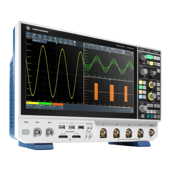
MXO 4 Series
Oscilloscope
Getting Started
(=SÃD2)
1335532002
Version 03
Table of
Contents
Previous
Page
Next
Page
1
2
3
4
5
Advertisement
Table of Contents
Need help?
Do you have a question about the MXO 4 Series and is the answer not in the manual?
Ask a question
Questions and answers
Related Manuals for Rohde & Schwarz MXO 4 Series
Test Equipment Rohde & Schwarz MXO 4 Series User Manual
(925 pages)
Test Equipment Rohde & Schwarz MXO4-BNDL Getting Started
(44 pages)
Test Equipment Rohde & Schwarz MXO44-242 Getting Started
(41 pages)
Test Equipment Rohde & Schwarz R&S MXO 5 Series Getting Started
(38 pages)
Test Equipment Rohde & Schwarz MXO 54 Getting Started
(44 pages)
Test Equipment Rohde & Schwarz MXO 5C Series Getting Started
(30 pages)
Test Equipment Rohde & Schwarz MXO44 Getting Started
(44 pages)
Test Equipment Rohde & Schwarz MXO 58 Getting Started
(44 pages)
Test Equipment Rohde & Schwarz CMW500 User Manual
Wideband radio communication tester (323 pages)
Test Equipment Rohde & Schwarz R&S RTB2004 User Manual
Digital oscilloscope (509 pages)
Test Equipment Rohde & Schwarz CTS60 Operating Manual
Digital radio tester for dect (224 pages)
Test Equipment Rohde & Schwarz R&S RTM3000 User Manual
(854 pages)
Test Equipment Rohde & Schwarz RTP044B Getting Started
High-performance oscilloscope (79 pages)
Test Equipment Rohde & Schwarz R&S RT-ZISO User Manual
Optical isolated probing system (51 pages)
Test Equipment Rohde & Schwarz CMU 300 Operating Manual
Universal radio communication tester (418 pages)
Test Equipment Rohde & Schwarz CMU200 Service Manual
Universal radio communication tester (216 pages)
This manual is also suitable for:
Mxo44-242
Mxo44-243
Mxo44-245
Mxo44-2410
Mxo44-2415
1335.5050p05
...
Show all
1335.5050p02
1335.5050p15
1335.5050k04
Mxo 4
Table of Contents
Print
Rename the bookmark
Delete bookmark?
Delete from my manuals?
Login
Sign In
OR
Sign in with Facebook
Sign in with Google
Upload manual
Upload from disk
Upload from URL


Need help?
Do you have a question about the MXO 4 Series and is the answer not in the manual?
Questions and answers