Table of Contents
Advertisement
Quick Links
Advertisement
Table of Contents

Related Manuals for Rohde & Schwarz TS-PSM1


Summary of Contents for Rohde & Schwarz TS-PSM1
- Page 1 ® R&S TS-PSM1 Power Switch Module User Manual (;[4Ò<) 1143.0468.12 ─ 07...
- Page 2 Subject to change – Data without tolerance limits is not binding. ® R&S is a registered trademark of Rohde & Schwarz GmbH & Co. KG. Trade names are trademarks of their owners. ® The following abbreviations are used throughout this manual: R&S TS-PSM1 is abbreviated as R&S TS-PSM1.
- Page 3 Basic Safety Instructions Always read through and comply with the following safety instructions! All plants and locations of the Rohde & Schwarz group of companies make every effort to keep the safety standards of our products up to date and to offer our customers the highest possible degree of safety. Our products and the auxiliary equipment they require are designed, built and tested in accordance with the safety standards that apply in each case.
- Page 4 Basic Safety Instructions Symbol Meaning Symbol Meaning Caution ! Hot surface Alternating current (AC) Protective conductor terminal Direct/alternating current (DC/AC) To identify any terminal which is intended for connection to an external conductor for protection against electric shock in case of a fault, or the terminal of a protective earth Earth (Ground) Class II Equipment...
- Page 5 Basic Safety Instructions Operating states and operating positions The product may be operated only under the operating conditions and in the positions specified by the manufacturer, without the product's ventilation being obstructed. If the manufacturer's specifications are not observed, this can result in electric shock, fire and/or serious personal injury or death. Applicable local or national safety regulations and rules for the prevention of accidents must be observed in all work performed.
- Page 6 Basic Safety Instructions 6. The product may be operated only from TN/TT supply networks fuse-protected with max. 16 A (higher fuse only after consulting with the Rohde & Schwarz group of companies). 7. Do not insert the plug into sockets that are dusty or dirty. Insert the plug firmly and all the way into the socket provided for this purpose.
- Page 7 Basic Safety Instructions 2. Before you move or transport the product, read and observe the section titled "Transport". 3. As with all industrially manufactured goods, the use of substances that induce an allergic reaction (allergens) such as nickel cannot be generally excluded. If you develop an allergic reaction (such as a skin rash, frequent sneezing, red eyes or respiratory difficulties) when using a Rohde &...
- Page 8 Basic Safety Instructions 2. Adjustments, replacement of parts, maintenance and repair may be performed only by electrical experts authorized by Rohde & Schwarz. Only original parts may be used for replacing parts relevant to safety (e.g. power switches, power transformers, fuses). A safety test must always be performed after parts relevant to safety have been replaced (visual inspection, protective conductor test, insulation resistance measurement, leakage current measurement, functional test).
- Page 9 Instrucciones de seguridad elementales 3. If you use the product in a vehicle, it is the sole responsibility of the driver to drive the vehicle safely and properly. The manufacturer assumes no responsibility for accidents or collisions. Never use the product in a moving vehicle if doing so could distract the driver of the vehicle.
- Page 10 Instrucciones de seguridad elementales Además queda en la responsabilidad del usuario utilizar el producto en la forma debida. Este producto está destinado exclusivamente al uso en la industria y el laboratorio o, si ha sido expresamente autorizado, para aplicaciones de campo y de ninguna manera deberá ser utilizado de modo que alguna persona/cosa pueda sufrir daño.
- Page 11 Instrucciones de seguridad elementales Símbolo Significado Símbolo Significado Conexión a tierra El aparato está protegido en su totalidad por un aislamiento doble (reforzado) Conexión a masa Distintivo de la UE para baterías y acumuladores Más información en la sección "Eliminación/protección del medio ambiente", punto 1.
- Page 12 Instrucciones de seguridad elementales Estados operativos y posiciones de funcionamiento El producto solamente debe ser utilizado según lo indicado por el fabricante respecto a los estados operativos y posiciones de funcionamiento sin que se obstruya la ventilación. Si no se siguen las indicaciones del fabricante, pueden producirse choques eléctricos, incendios y/o lesiones graves con posible consecuencia de muerte.
- Page 13 Instrucciones de seguridad elementales integran productos sin interruptor en bastidores o instalaciones, se deberá colocar el interruptor en el nivel de la instalación. 5. No utilice nunca el producto si está dañado el cable de conexión a red. Compruebe regularmente el correcto estado de los cables de conexión a red.
- Page 14 Instrucciones de seguridad elementales 17. No utilice el producto en condiciones en las que pueda producirse o ya se hayan producido condensaciones sobre el producto o en el interior de éste, como p. ej. al desplazarlo de un lugar frío a otro caliente.
- Page 15 Instrucciones de seguridad elementales pueden causar perturbaciones radioeléctricas en entornos residenciales debido a posibles perturbaciones guiadas o radiadas. En este caso, se le podrá solicitar al operador que tome las medidas adecuadas para eliminar estas perturbaciones. Aparato de clase B: Aparato adecuado para su uso en entornos residenciales, así...
- Page 16 Instrucciones de seguridad elementales 8. En caso de devolver baterías de litio a las filiales de Rohde & Schwarz, debe cumplirse las normativas sobre los modos de transporte (IATA-DGR, código IMDG, ADR, RID). Transporte 1. El producto puede tener un peso elevado. Por eso es necesario desplazarlo o transportarlo con precaución y, si es necesario, usando un sistema de elevación adecuado (p.
- Page 17 Customer Support Technical support – where and when you need it For quick, expert help with any Rohde & Schwarz equipment, contact one of our Customer Support Centers. A team of highly qualified engineers provides telephone support and will work with you to find a solution to your query on any aspect of the operation, programming or applications of Rohde &...
-
Page 18: Table Of Contents
® Contents R&S TS-PSM1 Contents 1 Usage...................... 5 2 View......................6 3 Block Diagram..................7 4 Layout..................... 9 5 Function Description................12 6 Commissioning..................14 7 Software....................15 8 Self-Test....................18 9 Interface description................19 10 Specifications..................26 User Manual 1143.0468.12 ─ 07... - Page 19 ® Contents R&S TS-PSM1 User Manual 1143.0468.12 ─ 07...
-
Page 20: Usage
An adapter frame can also be used if necessary. The control of the module is performed via the CAN bus. The high power lines are taken to the rear of the R&S TS-PSM1 via connection terminals and a 12-pin plug con- nector. -
Page 21: View
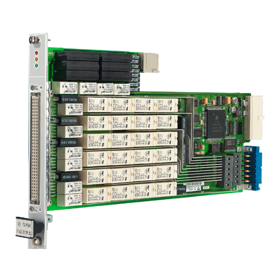
® View R&S TS-PSM1 2 View Figure 2-1 shows a view of the R&S TS-PSM1. Figure 2-1: View of the R&S TS-PSM1 User Manual 1143.0468.12 ─ 07... -
Page 22: Block Diagram
Block Diagram R&S TS-PSM1 3 Block Diagram Figure 3-1 shows the block diagram of the R&S TS-PSM1. A simplified view of the functional block can be seen in Figure 3-2. Figure 3-1: Block Diagram R&S TS-PSM1 User Manual 1143.0468.12 ─ 07... - Page 23 ® Block Diagram R&S TS-PSM1 Figure 3-2: Functional Block Diagram R&S TS-PSM1 User Manual 1143.0468.12 ─ 07...
-
Page 24: Layout
4 Layout 4.1 Mechanical Layout The R&S TS-PSM1 is designed as a long plug-in board for front mounting in the TSVP chassis. The mounting depth is 300 mm, and the front panel is 4U in height. Connector X20 is used to make the connections with the cPCI backplane / control backplane of the TSVP. - Page 25 Table 4-2: Display elements on the R&S TS-PSM1 Beschreibung Fault condition: (red) Lights up when a fault is detected on the R&S TS-PSM1 in the power-on test after the supply voltage is switched on. Communication: (yellow) Lights up briefly when the R&S TS-PSM1 is accessed via the interface.
- Page 26 ® Layout R&S TS-PSM1 R&S TS-PK04 Figure 4-3: R&S TS-PK04 Installation in R&S TS-PCA3 (cTSVP) Table 4-3: Connectors at Cable Set R&S TS-PK04 X3.A1 - - X1.7 CH01 COM X3.1 - - X2.A6 CH09 COM X3.A2 - - X1.2 CH02 COM X3.2 - - X2.A5...
-
Page 27: Function Description
7) 5.1 Signal Concept The special design of the R&S TS-PSM1 guarantees the ideal guiding of supply and load paths through the test system. Both “Force” channels with high currents and “Sense“ channels of voltage/current sources are guided across the R&S TS-PSM1 to the components on test. - Page 28 5.4 Compact Design The space-saving design of the R&S TS-PSM1 (1 slot) with voltage/ current monitoring and self-test on the analog bus allows the creation of very powerful and compact mea- surement and load systems with up to 12 modules in the CompactTSVP and 16 mod- ules in the PowerTSVP.
-
Page 29: Commissioning
The R&S TS-PSM1 plug-in module is correctly located when a distinct 'stop' can be felt ● Tighten the top and bottom screws on the front panel of the R&S TS-PSM1 plug-in module 6.1 Initializing the Plug-In Module Once the system has been powered up, the R&S TS-PSM1 is initialized. Signals GA0 ... -
Page 30: Software
7 Software 7.1 Driver Software A LabWindows CVI driver is provided for the R&S TS-PSM1 . This driver satisfies the IVI Switch specification. The driver is part of the ROHDE & SCHWARZ GTSL software. All the functions of the driver are described fully in the on-line help and in the LabWind- ows CVI Function Panel. - Page 31 R&S TS-PSM1 Program Example Figure 7-1: Softpanel R&S TS-PSM1 7.3 R&S TS-PSM1 Program Example Simple connection between ABa1 and ABb1 with TS-PSM1 in Slot 16 The coding rules of a GTSL software like allocating and locking the resource, or error handling are not considered in this example.
- Page 32 ® Software R&S TS-PSM1 R&S TS-PSM1 Program Example Creates a new IVI instrument driver and optionally sets the initial state of the session attributes. "CAN0::0::1::16": CAN board 0, Bus Controller 0, Frame 1, Slot 16 s_status = rspsm1_InitWithOptions ("CAN0::0::1::16", VI_TRUE, VI_TRUE, "", &...
-
Page 33: Self-Test
The power-on test runs at the same time as the LED test. The red LED lights up if a fault is found on the module. This is just a test of the firmware of the R&S TS-PSM1. 8.3 TSVP Self-Test The TSVP self-test runs an in-depth test on the module and generates a detailed log. -
Page 34: Interface Description
® Interface description R&S TS-PSM1 Terminal X2 9 Interface description 9.1 Connector X1 Figure 9-1: Connector X1 (mating side) Table 9-1: X1 Pinning Assignment Signal Signal LPBA CH1 COM CH2 COM CH6 COM CH3 COM CH4 COM LPBB LPBD CH5 COM... - Page 35 ® Interface description R&S TS-PSM1 Connector X10 9.3 Terminal X3 Figure 9-3: Terminal X3 9.4 Connector X10 Figure 9-4: Connector X10 (mating side) Table 9-2: X10 Pinning Assignment (Signals in bold print are High Power) CH1_NO CH1_NO CH1_NO CH1_NO CH1_NO...
- Page 36 ® Interface description R&S TS-PSM1 Connector X10 CH9_COM CH10_COM CH11_COM CH3_NO CH3_NO CH3_NO CH3_NO CH3_NO CH3_NO CH3_NO CH3_NO CH3_NO CH4_NO CH4_NO CH4_NO CH4_NO CH4_NO CH4_NO CH4_NO CH4_NO CH4_NO CH12_NO CH13_NO CH14_NO CH12_COM CH13_COM CH14_COM CH5_NO CH5_NO CH5_NO CH5_NO CH5_NO CH5_NO...
- Page 37 ® Interface description R&S TS-PSM1 Connector X20 9.5 Connector X20 F E D C B A Z Figure 9-5: Connector X20 (mating side) NC = not connected, NP = not populated 22 GND 21 GND PXI_LBR3 PXI_LBR2 PXI_LBR1 PXI_LBR0 20 GND...
- Page 38 ® Interface description R&S TS-PSM1 Connector X30 9.6 Connector X30 Figure 9-7: Connector X30 (mating side) Table 9-3: X30 Pinning Schedule ABc1 ABa1 ABb1 ABc2 ABb2 ABa2 ABd2 ABd1 IL1_x = IL1 of the slot User Manual 1143.0468.12 ─ 07...
- Page 39 ® Interface description R&S TS-PSM1 R&S TS-PK04 9.7 R&S TS-PK04 9.7.1 Connector X3 Figure 9-8: Connector X3 - Rear Side R&S TS-PCA3 or R&S TS-PWA3 Table 9-4: Pinning Assignment X3 Signal Signal CH1_COM CH9_COM CH2_COM CH10_COM CH3_COM CH11_COM CH4_COM CH12_COM...
- Page 40 ® Interface description R&S TS-PSM1 R&S TS-PK04 9.7.2 Connector X4 Figure 9-9: Connector X4 - Rear Side R&S TS-PCA3 or R&S TS-PWA3 Table 9-5: Pinning AssignmentrX4 Signal Signal CH5_COM CH13_COM CH6_COM CH14_COM CH7_COM CH15_COM CH8_COM CH16_COM LPBC IL1_COM LPBD User Manual 1143.0468.12 ─ 07...
-
Page 41: Specifications
R&S TS-PSM1 10 Specifications The technical data of the Power Switch Module R&S TS-PSM1 are shown in the corre- sponding data sheets. In the event of any discrepancies between date in this user manual and technical data in the data sheet, the data sheet takes precedence.
Need help?
Do you have a question about the TS-PSM1 and is the answer not in the manual?
Questions and answers