
Subscribe to Our Youtube Channel
Related Manuals for Rohde & Schwarz RTP044B


Summary of Contents for Rohde & Schwarz RTP044B
- Page 1 ® R&S High-Performance Oscilloscope Getting Started (B3ÎÜ2) 1803647802 Version 01...
- Page 2 ® This manual describes the following R&S RTP models with firmware version 5.15 and higher: ● R&S ® RTP044B (1803.7000K04) ● R&S ® RTP064B (1803.7000K06) ● R&S ® RTP084B (1803.7000K08) ● R&S ® RTP134B (1803.7000K13) ● R&S ® RTP164B (1803.7000K16) ©...
-
Page 3: Table Of Contents
® Contents R&S Contents 1 Safety and regulatory information........5 1.1 Safety instructions................5 1.2 Labels on the product.................11 1.3 Warning messages in the documentation........12 1.4 Where to find key documents on Rohde & Schwarz....... 12 1.5 Korea certification class A..............13 2 Key features................. - Page 4 ® Contents R&S 5.3 Keys and controls................33 6 Operating the instrument............41 6.1 Means of manual interaction............. 41 6.2 Touchscreen display................42 6.3 Applications..................49 6.4 Working with waveforms..............50 6.5 Rohde & Schwarz SmartGrid............. 53 6.6 Toolbar....................54 6.7 Displaying results................63 6.8 Using dialogs..................
-
Page 5: Safety And Regulatory Information
® Safety and regulatory information R&S Safety instructions Safety and regulatory information The product documentation helps you to use the product safely and efficiently. Follow the instructions provided here and in the Chapter 1.1, "Safety instructions", on page 5. Intended use The R&S RTP oscilloscope is designed for measurements on circuits that are only indirectly connected to the mains or not connected at all. - Page 6 ® Safety and regulatory information R&S Safety instructions Using the product requires specialists or specially trained personnel. These users also need sound knowledge of at least one of the languages in which the user interfaces and the product documentation are available. Never open the casing of the product.
- Page 7 ® Safety and regulatory information R&S Safety instructions Setting up the product Always place the product on a stable, flat and level surface with the bottom of the product facing down. If the product is designed for different positions, secure the product so that it cannot fall over.
- Page 8 ® Safety and regulatory information R&S Safety instructions ● Only use intact cables and route them carefully so that they cannot be dam- aged. Check the power cables regularly to ensure that they are undamaged. Also ensure that nobody can trip over loose cables. ●...
- Page 9 ® Safety and regulatory information R&S Safety instructions tweezers or pliers to avoid injuries. When transporting the accessories, always use the box supplied with the probe. ● Prevent the probe from receiving mechanical shock. Avoid putting excessive strain on the probe cable or exposing it to sharp bends. Touching a broken cable during measurements can cause injuries.
- Page 10 ® Safety and regulatory information R&S Safety instructions ● The following effects can cause burns and fire or damage to the measurement site: – Eddy current loss can cause heating of the sensor head. – Dielectric heating can cause heating of cord insulation and other materials. Measurement categories IEC 61010-2-030 defines measurement categories that rate instruments on their ability to resist short transient overvoltages that occur in addition to the working...
-
Page 11: Labels On The Product
® Safety and regulatory information R&S Labels on the product Cleaning the product Use a dry, lint-free cloth to clean the product. When cleaning, keep in mind that the casing is not waterproof. Do not use liquid cleaning agents. Meaning of safety labels Safety labels on the product warn against potential hazards. -
Page 12: Warning Messages In The Documentation
® Safety and regulatory information R&S Where to find key documents on Rohde & Schwarz Warning messages in the documentation A warning message points out a risk or danger that you need to be aware of. The signal word indicates the severity of the safety hazard and how likely it will occur if you do not follow the safety precautions. -
Page 13: Korea Certification Class A
® Safety and regulatory information R&S Korea certification class A Korea certification class A 이 기기는 업무용(A급) 전자파 적합기기로서 판매자 또는 사용자는 이 점을 주의하 시기 바라며, 가정외의 지역에서 사용하는 것을 목적으로 합니다. Getting Started 1803.6478.02 ─ 01... -
Page 14: Key Features
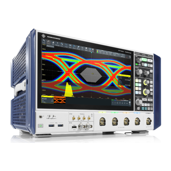
® Key features R&S Key features The R&S RTP high-performance oscilloscopes combine superior signal integrity with fastest acquisition rate. It combines multiple instrument capabilities for time- correlated debugging in one box. Outstanding key features are: Real-time signal integrity ● Superior frontend performance ●... -
Page 15: Documentation Overview
® Documentation overview R&S Manuals and instrument help Documentation overview This section provides an overview of the R&S RTP user documentation. Manuals and instrument help You find the manuals on the product page at: www.rohde-schwarz.com/manual/rtp Getting started manual Introduces the R&S RTP and describes how to set up and start working with the instrument, and describes basic operations. - Page 16 ® Documentation overview R&S Manuals and instrument help – eMMC Compliance Tests Procedures – PCIe Compliance Tests Procedures – DDR3 Compliance Tests Procedures – DDR4 Compliance Tests Procedures – HDMI Tests Procedures – ScopeSuite Automation ● The following test fixture manuals are available: –...
-
Page 17: Data Sheet And Brochure
® Documentation overview R&S Application notes, application cards, videos Data sheet and brochure The data sheet contains the technical specifications of the R&S RTP. It also lists the options with their order numbers and optional accessories. The brochure pro- vides an overview of the instrument and deals with the specific characteristics. www.rohde-schwarz.com/brochure-datasheet/rtp Release notes, open source acknowledgment The release notes list new features, improvements and known issues of the cur-... -
Page 18: Preparing For Use
® Preparing for use R&S Choosing the operating site Preparing for use Here, you can find basic information about setting up the instrument for the first time or when changing the operating site. Lifting and carrying See: "Lifting and carrying the instrument" on page 6. -
Page 19: Setting Up The Product
® Preparing for use R&S Setting up the product Electromagnetic compatibility classes The electromagnetic compatibility (EMC) class indicates where you can operate the product. The EMC class of the product is given in the data sheet. ● Class B equipment is suitable for use in: –... - Page 20 ® Preparing for use R&S Setting up the product 3. CAUTION! A stack of products can fall over and cause injury. Never stack more than two products. Otherwise, mount them in a rack. Stack as follows: ● All products must have the same dimensions (width and length). ●...
-
Page 21: Considerations For Test Setup
® Preparing for use R&S Considerations for test setup Design and implement an efficient ventilation concept for the rack. To mount the R&S RTP in a rack 1. Use an adapter kit that fits the dimensions of the R&S RTP to prepare the instrument for rack mounting. -
Page 22: Connecting To Power
® Preparing for use R&S Connecting to power Signal input and output levels Information on signal levels is provided in the data sheet. Keep the signal levels within the specified ranges to avoid damage to the product and connected devi- ces. -
Page 23: Switching On Or Off
® Preparing for use R&S Switching on or off 2. Plug the AC power cable into a power outlet with ground contact. The required ratings are listed next to the AC power connector and in the data sheet. Switching on or off The instrument is switched on or off with the power switch and the [Power] key. -
Page 24: Connecting External Devices
® Preparing for use R&S Connecting external devices All current settings are saved, and the software shuts down. The [Power] key turns orange. The standby power supplies only the power switch circuits. "Exit" icon in the "Menu" shuts down only the firmware application. To shut down the instrument completely, use the [Power] key. - Page 25 ® Preparing for use R&S Connecting external devices When a USB device is disconnected from the R&S RTP, Windows immediately detects the change in hardware configuration and deactivates the corresponding driver. The properties of external USB devices are configured in the operating system, not in the instrument's firmware.
- Page 26 ® Preparing for use R&S Connecting external devices 3. You can configure the displays directly in the instrument's setup. Open "Menu" > "Settings" > "Display". 4. Select the "Monitors" tab. 5. Select how to display the screen. Select "Extend" to arrange dialogs and result boxes on different displays.
-
Page 27: Instrument Tour
® Instrument tour R&S Front panel Instrument tour This chapter describes the front and rear panels of the instrument including all function keys and connectors. Front panel This section provides an overview of the R&S RTP front panel and explains the various connectors and the option slots at the front. - Page 28 ® Instrument tour R&S Front panel 6 = External trigger input 7 = Analysis keys 8 = Input channels 9 = Two option slots for R&S RTP-B1 (MSO) or R&S RTP-B1E (for R&S RT-ZVC) , R&S RTP- B6 (waveform generator), R&S RTP-B7 (pulse source) 10 = USB connectors 11 = Connectors for probe compensation and grounding 12 = [Power] key...
- Page 29 ® Instrument tour R&S Front panel Square wave signal for probe compensation, 1 kHz and 1 V Ground connector for probes. 5.1.2 Option slots Three options R&S RTP-B1/B6/B7 can be installed in one R&S RTP - two at the front panel, and one at the rear panel. Each option can be installed only once, and the slot assignment depends on the available options.
-
Page 30: Rear Panel
® Instrument tour R&S Rear panel The module has four connectors. ● Out, : 2.92 mm connectors (K type) for pulse signal output ● Ref, : 2.92 mm connectors (K type) for reference signal output Rear panel This section explains the rear panel of the R&S RTP, including the various con- nectors and the option slot. - Page 31 ® Instrument tour R&S Rear panel 8 = GPIB connector 9 = Exchangeable solid state disk (SSD, option R&S RTP-B19) 10 = Aux Out connector 11 = External trigger output 12 = Ref In, Ref Out: reference input and output of the OCXO reference signal 13 = Option slot 14 = Digital data interface (DDI, optional) AC power supply connector and main power switch...
- Page 32 ® Instrument tour R&S Rear panel GBIP Connector with GBIP interface. For detailed specifications, refer to the data sheet. Aux Out Output of the internal calibration signal, if the signal is configured to external des- tination. Trigger Out The BNC connector for external trigger output is used to provide the internal trig- ger signal of the oscilloscope to trigger other instruments for synchronized mea- surements.
-
Page 33: Keys And Controls
® Instrument tour R&S Keys and controls Keys and controls For an overview of the front panel keys, see Figure 5-1. 5.3.1 Power key The [Power] key is located on the lower left corner of the front panel. It starts up and shuts down the instrument's software. - Page 34 ® Instrument tour R&S Keys and controls [Auto Norm] Toggles the trigger mode between "Auto" and "Normal". The current setting is shown on the trigger label. Auto The instrument triggers repeatedly after a time interval if the trigger conditions are not fulfilled. Norm The instrument acquires a waveform only if a trigger occurs.
- Page 35 ® Instrument tour R&S Keys and controls [Position] The rotary knob changes the horizontal position of the waveform or the position of the reference point on the screen. To set the value to zero, press the knob. The current value is shown in the input box in the upper right corner of the screen. You can select if the knob changes the position or the reference point in "Menu"...
- Page 36 ® Instrument tour R&S Keys and controls The effect of the keypress depends on state of the channel: ● If channel is off: turns on the channel and selects it. ● If the channel is on and in focus (selected): opens the corresponding channel dialog.
- Page 37 ® Instrument tour R&S Keys and controls ● Position indicates the vertical location in divisions. ● Offset moves the vertical center of the selected channel to the offset value. If the selected waveform is a math or reference waveform, serial bus, or logic channel, the knob changes its vertical position.
- Page 38 ® Instrument tour R&S Keys and controls [Peak] Opens the "Peak List" dialog, where you can enable the peak list generation and configure the display of the peak list [User] Opens the "Frontpanel" settings dialog, where you can configure the function of the camera key.
- Page 39 ® Instrument tour R&S Keys and controls Press the [Intensity] key and turn the [Multiuse] knob. Press the [Intensity] key again to toggle between the three settings. The controlled parameter and its value are shown in the input box in the upper right corner of the screen. [Cursor] Starts a cursor measurement: displays vertical and horizontal cursor lines in the active diagram, and the results of the cursor measurement.
- Page 40 ® Instrument tour R&S Keys and controls [Preset] Resets the instrument to a default state. All measurements, mask tests, zoom, and most individual settings are deleted, and all channels except for channel 1 are disabled. You can define preset configurations and save them to a file. The [Preset] key can be configured to set either factory defaults or a user-defined pre- set configuration.
-
Page 41: Operating The Instrument
® Operating the instrument R&S Means of manual interaction Operating the instrument There are three ways to operate the R&S RTP. Manual operation Use the touchscreen, keys and rotary knobs, or an optional mouse and/or key- board. The principles of manual operation are explained in this section. Remote control Create programs to automatize repeating settings, tests, and measurements. -
Page 42: Touchscreen Display
® Operating the instrument R&S Touchscreen display Using the touchscreen is the direct interaction way. Use your finger to place waveforms on the screen, mark areas for zoom and histograms, set parame- ters in dialog boxes, enter data, and much more. The control elements and actions on the screen are based on common concepts, and you will easily become familiar with the user interface. - Page 43 ® Operating the instrument R&S Touchscreen display Figure 6-1: Display information 1 = Diagram 2 = Grid 3 = Trigger position 4 = Reference point (distance from trigger position to reference point = horizontal position) 5 = Trigger, horizontal and acquisition label 6 = Notifications 7 = Zoom area 8 = Zoom diagram...
- Page 44 ® Operating the instrument R&S Touchscreen display By default, the diagram name contains the diagram number and the short names of the waveforms shown inside. To change the diagram name, touch and hold the tab name. The on-screen keyboard opens to enter the new name. Names must be unique.
- Page 45 ® Operating the instrument R&S Touchscreen display Figure 6-3: Horizontal label on the toolbar 1 = Time scale 2 = Horizontal position Figure 6-4: Acquisition label on the toolbar 1 = Sample rate 2 = Record length 3 = Decimation 4 = Number of acquired waveforms Reference point The reference point marks the rescaling center.
- Page 46 ® Operating the instrument R&S Touchscreen display As for waveform diagrams, you can change the name of the zoom diagram. A zoom in a zoom and coupled zooms are also possible. All zooming possibilities are described in detail in the user manual, chapter "Zoom".
- Page 47 ® Operating the instrument R&S Touchscreen display Histogram and histogram area A histogram shows the frequency of occurrence of voltage or time values in a bar chart directly in the diagram. The rectangular histogram area indicates the part of the waveform that is considered in the histogram. The vertical histogram counts the voltage values, and the horizontal histogram counts time values.
- Page 48 ® Operating the instrument R&S Touchscreen display = Toolbar = Tab in a dialog box = Dialog box = Result table (docked) = Signal bar = Menu Not shown = Input box Toolbar (1) The icons on the toolbar provide quick and easy access to the most important functionality.
-
Page 49: Applications
® Operating the instrument R&S Applications Input box The input box appears if you adjust a value using one of the rotary knobs, or if you drag an element on the screen, for example, a cursor line. The input box shows the current value of the modified parameter. -
Page 50: Working With Waveforms
® Operating the instrument R&S Working with waveforms Working with waveforms The R&S RTP can create and display many waveform types. The most importand are: ● Channel waveforms: Up to three waveforms per input channel can be shown. For a four-channel instrument, 12 channel waveforms are available. - Page 51 ® Operating the instrument R&S Working with waveforms Show the details of waveforms. ● XY-waveforms: Four XY-waveforms can be created. Each XY-waveform is built from the volt- age values of two source waveforms. ● Digital waveforms: The Mixed Signal Option R&S RTP-B1 provides 16 digital channels grouped in two logic probes (pods) with 8 channels each.
- Page 52 ® Operating the instrument R&S Working with waveforms The vertical [Position] and the [Scale] knobs are illuminated in the color of the selected waveform. Figure 6-1, C1 is the selected waveform: The frame of the diagram and the signal icon are highlighted. ●...
-
Page 53: Rohde & Schwarz Smartgrid
® Operating the instrument R&S Rohde & Schwarz SmartGrid To switch off a waveform ► Do one of the following: ● To switch off a signal preview, tap the "Close" icon in the upper right corner of the minimized signal view. ●... -
Page 54: Toolbar
® Operating the instrument R&S Toolbar To arrange a waveform using the SmartGrid You can arrange waveforms in one of the existing diagrams, or in a new diagram. 1. Drag the signal icon to the diagram area, and move it around. The Rohde &... - Page 55 ® Operating the instrument R&S Toolbar By default, the toolbar shows the most frequently used functions. You can config- ure the content of the toolbar, see Chapter 6.6.2, "Configuring the toolbar", on page 56. 6.6.1 Using the toolbar Using the toolbar is easy and straightforward. Some of the toolbar functions are one-click actions.
- Page 56 ® Operating the instrument R&S Toolbar 4. To define the analyzed area, do one of the following: ● Tap the required diagram. ● Drag a rectangle on the diagram. 6.6.2 Configuring the toolbar You can configure the content of the toolbar so that only the required functions are displayed.
- Page 57 ® Operating the instrument R&S Toolbar A detailed description of the toolbar functions is given in Chapter 6.6.3, "Toolbar functions", on page 57. 6.6.3 Toolbar functions This section describes all toolbar functions in detail. One-click actions Interactive actions Undo Zoom Redo Search Help...
- Page 58 ® Operating the instrument R&S Toolbar One-click actions Interactive actions Find Level Save Waveform Force Trigger Zone trigger Demo Spectrogram (option R&S RTP-K37) You can configure the content of the toolbar, see Chapter 6.6.2, "Configuring toolbar", on page 56. The following list describes at first the default toolbar functions and then the addi- tional functions.
- Page 59 ® Operating the instrument R&S Toolbar Image Saves a screenshot of the current display using the settings defined in "Menu" >"Save/Recall" > "Save" tab > "Screenshot". Report Creates a report of the current measurement settings and results using the settings defined in "Menu" > "Save/Recall" > "Save" tab > "Report". Clear Deletes all measurement results including long term measurement and sta- tistics, all waveforms, and the history.
- Page 60 ® Operating the instrument R&S Toolbar Standard zoom ← Zoom Displays a magnified section of the diagram in an additional zoom diagram. It is a display zoom, instrument settings are not changed. Tap the icon and drag a rectangle on the diagram to mark the zoom area. An additional zoom diagram appears.
- Page 61 ® Operating the instrument R&S Toolbar Tap the diagram where you want to set the cursors, or draw a rectangle in the dia- gram to position the cursor lines. The resulting cursor lines measure the selected waveform, and the results are shown. Mask Test Starts the on-screen mask definition and the testing against the defined mask.
- Page 62 ® Operating the instrument R&S Toolbar Transforms a waveform to the frequency spectrum by fast Fourier trans- form (FFT). The FFT trace is shown in a new diagram. Tap the icon and adjust the settings in the overlay menu. Select the source of the spectrum in the overlay menu.
-
Page 63: Displaying Results
® Operating the instrument R&S Displaying results Tap the icon. Select the source in the sidebar, or tap diagram with the waveform to be transformed. The diagrams are created from the selected waveform. Delete Removes waveforms, measurements, zoom, histograms, mask segments and other elements from the display. - Page 64 ® Operating the instrument R&S Displaying results To arrange the results on the display 1. If the results are listed in a docked table, touch and hold a result line and drag The results are now shown in a floating result box. Note: Once you undock the measurement results, you cannot move the result box back to the docked position.
-
Page 65: Using Dialogs
® Operating the instrument R&S Using dialogs 2. In the overlay menu, tap "Advanced Setup". The corresponding dialog opens. To adjust the font size of results 1. Open the "Menu" > "Settings" > "Appearance" dialog. 2. Select the "Dialogs" tab. 3. -
Page 66: Entering Data
® Operating the instrument R&S Entering data Minimizes the dialog box to a small box that only contains the last selected func- tion. Closes the dialog box. To minimize a dialog If you want to change only one setting during analysis, and you need to change it often, you can display a small box that only contains the required setting. - Page 67 ® Operating the instrument R&S Entering data 2. Press the knob: ● [Scale]: toggles the increment. ● [Position]: sets to zero. ● [Level]: sets the trigger level to 50% of the signal. 3. The input box also has settings: ● Tap the "Steps" icon to toggle the increment. ●...
-
Page 68: Instrument Information And Notifications
® Operating the instrument R&S Instrument information and notifications To toggle between small steps and large steps, tap the "Steps" icon. ● To get the value that was used before the keypad opened, tap "Cur". ● To enter a user-defined value, tap the numbers and complete the entry by tapping the unit button. -
Page 69: Getting Help
® Operating the instrument R&S Getting help ► To see the instrument information, tap the Rohde & Schwarz logo. Notifications are status messages, information on mismatching settings and simi- lar information. They are displayed for a few seconds and saved. The color of the dot before the text indicates the severity: gray for information, orange for warnings, and red for errors. - Page 70 ® Operating the instrument R&S Getting help ● Tooltips give a short description of the parameter. ● The context help provides functional description on a setting, and the corre- sponding remote command. ● The general help opens the help window with a table of contents, where you can browse and search for information.
- Page 71 ® Operating the instrument R&S Getting help ● "Contents" - contains a table of help contents ● "Index" - contains index entries to search for help topics ● "Search" - provides text search The Help toolbar provides some buttons: ● To browse the topics in the order of the table of contents: up arrow = previous topic, down arrow = next topic ●...
- Page 72 ® Operating the instrument R&S Getting help "trigger qualification". A search for trigger qualification finds all topics that contain the words trigger and qualification. ● Use "Match whole word" and "Match case" to refine the search. ● Use operators AND, OR, and NOT. To close the Help window ►...
-
Page 73: Setting Up The Instrument
® Setting up the instrument R&S Performing a self-alignment Setting up the instrument Basic setup procedures for the instrument are the following: ● Performing a self-alignment................73 ● Setting the display language................74 Performing a self-alignment The self-alignment aligns the data from several input channels vertically and hori- zontally to synchronize the timebases, amplitudes and positions. -
Page 74: Setting The Display Language
® Setting up the instrument R&S Setting the display language Setting the display language You can change the language in which the dialog boxes, result boxes and other screen information is displayed. A reboot of the instrument is not necessary. 1. -
Page 75: Contacting Customer Support
® Contacting customer support R&S Contacting customer support Technical support – where and when you need it For quick, expert help with any Rohde & Schwarz product, contact our customer support center. A team of highly qualified engineers provides support and works with you to find a solution to your query on any aspect of the operation, program- ming or applications of Rohde &... -
Page 76: Index
® Index R&S Index Digital waveforms ........50 Display Acquisition Overview ..........42 Single, multiple ........33 Display elements ........47 Start and stop ........33 Diagram ..........42 Active waveform ........51 Signal bar ..........42 Aligning DisplayPort ........25, 31 Input channels ........ - Page 77 ® Index R&S R&S RTP-B1E (for R&S RT-ZVC) ..29 R&S RTP-B6 (waveform and function Keyboard generator) ........... 29 On-screen ........... 66 Usage ..........41 Keyboard, connecting ......25 Position ............36 Keypad ............ 66 Horizontal ..........35 Vertical ..........36 Power Connector ........... 31 Connector ...........
- Page 78 ® Index R&S Searching Search ..........60 In help ..........71 Show tooltips ........58 Select Single ..........59 Waveform ..........52 Undo ........... 58 Selected waveform ........51 Zone trigger ........62 Self-alignment ......... 73 Zoom ...........60 Service manual ........16 Tooltips ............
- Page 79 ® Index R&S Switch off ..........53 Switch on ..........52 Web interface .......... 41 XY-waveforms ......... 50 Zone key ..........34 Zone trigger ........34, 62 Zoom Area ............ 45 Diagram ..........45 Key ............35 Quick access ........60 Waveforms .......... 50 Getting Started 1803.6478.02 ─...
Need help?
Do you have a question about the RTP044B and is the answer not in the manual?
Questions and answers