
Subscribe to Our Youtube Channel
Related Manuals for Miranda NV9640


Summary of Contents for Miranda NV9640
- Page 1 NV9640 Control Panel User’s Guide Miranda Technologies Inc. 3499 Douglas B. Floreani Montreal, Quebec Canada H4S 2C6...
- Page 2 The information and intellectual property contained herein is confidential between Miranda and the client and remains the exclusive property of Miranda. If you find any problems in the documentation, please report them to us in writing. Miranda does not warrant that this document is error-free.
- Page 3 Contact Miranda for details on the software license agreement and product warranty. Technical Support Contact Information Miranda has made every effort to ensure that the equipment you receive is in perfect working order and that the equipment fits your needs. In the event that problems arise that you cannot resolve, or...
- Page 4 ‘Page VFD only’ option added. Restriction on Hazardous Substances (RoHS) Miranda is in compliance with EU Directive RoHS 2002/95/EC governing the restricted use of cer- tain hazardous substances and materials in products and in our manufacturing processes. Miranda has a substantial program in place for RoHS compliance that includes significant invest- ment in our manufacturing process, and a migration of Miranda product electronic components and structural materials to RoHS compliance.
- Page 5 The fuse symbol indicates that the fuse referenced in the text must be replaced with one having the ratings indicated. The presence of this symbol in or on Miranda equipment means that it has been designed, tested and certified as complying with applicable Underwriter’s Laboratory (USA) regulations and rec- ommendations.
- Page 6 General Warnings A warning indicates a possible hazard to personnel which may cause injury or death. Observe the following general warnings when using or working on this equipment: • Heed all warnings on the unit and in the operating instructions. •...
- Page 7 NV9640 Panel Configuration Page ........
- Page 8 Table of Contents Selection Buttons ............. 35 Selection Button Behavior .
- Page 9 The GPIO Section of the NV9640 Page ........
- Page 10 NV9640 Specifications ........
- Page 11 1. Preface Chapter 1 is an introduction to the NV9640 User’s Guide. It presents the following topics: • Chapter Structure • The PDF Document • Terms, Conventions and Abbreviations Chapter Structure The following chapters provide detailed information regarding the NV9640 Control Panel: •...
- Page 12 • Press the SRC 12 button ... The following terms and abbreviations are used throughout this guide: • The term “control panel” refers to the NV9640 control panel and to NV96xx control panels, in general. • “High tally” means that a button is brightly illuminated.
- Page 13 4 optically isolated relay outputs and 8 optically isolated inputs: Power Ethernet GPIO (tally) Serial (RS-232) Figure 2-2. NV9640 Rear 1 An equivalent NV9640V — a GUI that is called a “virtual panel”— is available. It emulates the NV9640. NV9640 Control Panel • User’s Guide...
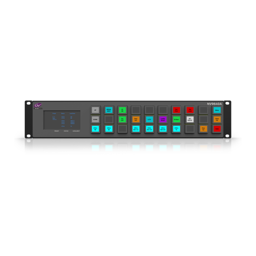
- Page 14 Panel Organization Function Buttons The NV9640 has an array of 30 LCD buttons. Each has 3 lines of text (up to 8 characters per line). The buttons can display one of seven colors dynamically: nominally red, green, blue, purple, amber, yellow, or grey. We say a button is “dark” when its LCD is turned off.
- Page 15 In the illustration above, ‘VTR 1’ was selected. Operators might need to scroll to see or select a level. In MD mode, the ‘Level/Dest’ column presents all the MD destinations defined in the NV9640 configuration. (Actual destinations are defined in the NV9000 configuration.) Operators might...
- Page 16 An ‘L’ indicates that a device has been locked. A ‘P’ indicates that a device has been protected. NV9640 operators may lock, protect or release destinations. It is important for operators to know that other operators may lock, protect, or release sources and destinations.
- Page 17 • Salvo mode — pressing a Salvo button (and then the ‘Take’ button) executes a salvo. (The dura- tion of a salvo is indeterminate.) • Menu mode — pressing a Menu button places the NV9640 in “menu” mode. In menu mode, the LCD button array becomes a menu that changes as needed during menu operation.
- Page 18 • Device selection using indexes or suffixes. The NV9640 provides the following additional features: • The NV9640 supports multiple-level breakaways in X-Y mode. This lets you route multiple sources to the same destination on different levels. • The panel supports gang or dub switching in multi-destination mode.
- Page 19 Depending on your order, the NV9640 items that can ship include: • One or more NV9640 control panels. • One or two power supplies for each NV9640, with straps that secure the AC power cords to the power supplies. • Optional WC0053 breakout cable.
- Page 20 NV9000 configuration software. You may use the Panel IP Configuration Utility if you want to your NV9640 to have a static IP address or to use DHCP. The panel, as it comes from the factory, defaults to DHCP.
- Page 21 You can now prepare an NV9640 configuration in NV9000-SE Utilities and upload the configura- tion to the NV9640. You need the panel ID to create a NV9640 configuration. When you upload the configuration, the panel ID you entered in NV9000-SE Utilities designates the actual panel to which the upload will occur.
- Page 22 3. Installation Testing Testing As shown above in step 3, a panel test function is available when the NV9640 is disconnected from the system controller. Run the test to determine the health of your NV9640. See Setup Mode page 71 for detail. Press the ‘Software Versions’ button to review the versions of installed software and firmware.
- Page 23 The NV9640, in addition, has an 8×42 alphanumeric display that presents the status of operations as they occur. An NV9640 panel should be configured with at least one ‘Page Up’ button and at least one ‘Page Down’ button with which the operator can scroll the display.
- Page 24 Choose “NV9640” from the ‘Type’ field. In the ID field, enter the panel ID you assigned to the panel while it was in setup mode. Give a name to the panel in the name field and select a user.
- Page 25 Global Navigation on page 40. Return to the ‘Control Panels’ page to view your new entry. To edit an NV9640 configuration, either double-click its list entry or select the entry with a check in the checkbox and then click ‘Edit Selected Control Panels’:...
- Page 26 Page Table GPIO Definitions Figure 4-1. NV9640 Configuration Page (Default) Similar pages exist for NV9640 suffix templates and for global navigation templates. See Global Navigation on page 40. After you configure buttons, and button pages, the appearance of the panel buttons will have changed.
- Page 27 In this section, configurers may specify the behavioral characteristics of the panel. Configuration Tasks The person configuring an NV9640 panel will want to consider how best to use the hierarchical nature of the button tree to support the devices and routers in the router control system at hand. The task is non-trivial.
- Page 28 In particular, the operator, having navigated down a subtree, must have some way to navigate back up the subtree. There are several ways to ensure this. Two are listed here: • Place a “Back” button on each subpage. The “back” button causes the NV9640 to redisplay the previous page.
- Page 29 Your configuration should have at least one ‘Page Up’ and ‘Page Down’ button if you wish to do this. A double-click is required. It is assumed that the configuration loaded in the NV9640 and available to operators will have the same ‘Page Up’ and ‘Page Down’ buttons.
- Page 30 4. Configuration Panel Options XY Data Automatic If a machine control (i.e., data) level is involved in a route, the system Routing Mode makes the route on the control level even if the control port is in use on the source or destination device. It breaks the previous control connection and then makes a new control connection for the route in progress.
- Page 31 Check ‘Enable Destination Lock’ so that any ‘Destination Lock’ button on the panel will func- tion. • Enable Destination Protect. Check ‘Enable Destination Protect’ so that any ‘Destination Protect’ button on the panel will function. NV9640 Control Panel • User’s Guide...
- Page 32 A ‘Src/Dst’ button connects a source to a destination. When this box is checked (as it is in the default NV9640 configuration) the button performs an immediate take. When the box is clear, the button sets up the take and the operator must press a ‘Take’ button to complete the take.
- Page 33 The set of devices in a category can change over time (as the configuration database changes); the NV9640 device list changes also. The number and names of categories can also change over time and the NV9640 will track those changes too.
- Page 34 4. Configuration Button Definitions Button Specification The button definitions section has several controls: The controls vary according to the button type. Button Type A pull-down menu where you may select a button type. Button Caption Three text boxes in which you can enter three lines of button text up to 8 charac- ters each.
- Page 35 Note that different subsets of these button types are available when you are defining a global suffix template or a global navigation template. See Global Navigation on page 40. These are the button types available for NV9640 configurations: Type Description Back The ‘Back’...
- Page 36 4. Configuration Button Definitions Type Description Clear Preset Erases preset entries, while leaving the panel in the same mode. We recommend you use this button because it is a “safety” feature. The clear preset button has the side effect of switching off ‘Save Preset’ mode. Default State Returns the panel to its most recent power-up state.
- Page 37 Menu This button puts the NV9640 panel in menu mode and displays a menu on the LCD buttons that provides access to a variety of panel options. The button is required if you want the user to have access to the menu.
- Page 38 4. Configuration Button Definitions Type Description Page Up Scrolls a list up. Lists include categories, source devices, and destination devices. Scrolling is necessary when the list exceeds the number of buttons available for the the list. “Page Up’ also scrolls through multi-destination devices in multi-destination mode and through levels in X-Y mode.
- Page 39 “source is master” and “destination is master,” and the button, if present, is high-tally by default. The ‘Source is Master’ button is also used to initiate “broadcast” control routes. See Broadcast Routes on page 67. NV9640 Control Panel • User’s Guide...
- Page 40 A source/destination button selects both a source and a destination at one time. Destination Source/destination buttons can be configured to perform immediate takes. (It is a NV9640 panel option.) If they are not so configured, the operator must also press a ‘Take’ button to effect a take. Take In X-Y mode, a take button switches the preset source device to the selected desti- nation device on selected levels.
- Page 41 This option creates a new page in the button tree. During operation, the navigation button you are creating will cause the NV9640 to display, or jump to, that page. The name of the page and the button caption are what you type in the three lines for the button caption. You can change the name of the page in the button page list.
- Page 42 The fill occurs in left-to-right, top-down, order: During operation, the navigation button will cause the NV9640 to display the first of the auto- fill pages. The operator uses the back and forward buttons to scroll through the list.
- Page 43 Be aware when deleting pages from the tree that the deletion does not remove any navigation buttons from any button page. NV9640 Control Panel • User’s Guide...
- Page 44 4. Configuration Button Page List This is a sample of a button page list: It represents this tree structure: 1 Default 2 Router Sources 6 Router Dests 9 UTILITY 3 Prod Sources 5 TOC Sources 7 Prod Dests 8 TOC Dests 10 Random Sources You can change the name of a page by double-clicking the page’s name field and editing its text.
- Page 45 It has two sections: inputs and outputs. By clicking on one of the input or output buttons, you can configure the input or output. (The NV9640 has no actual tally buttons. These buttons represent the DB25 connector at the rear. The buttons are present in the configuration page to allow you to configure the tally interface.) If you are interested in configuring the tally interface, read Chapter 6, GPIO, on page 75.
- Page 46 4. Configuration Selection Buttons Selection Button Behavior XY Mode When the panel is in XY mode, a set of selection buttons presents a set of virtual levels. The levels displayed on the buttons correspond to the levels in the level set of a selected destination device. If a selection button is dark and blank, the level does not exist in the level set.
- Page 47 You can create many different forms of “single-destination” mode. This mode need not have just one destination. 1. The term display index means something quite different on certain other panels such as the NV9641. NV9640 Control Panel • User’s Guide...
- Page 48 4. Configuration Multi-Destination Configuration The simplest form presents a group of “quick source” buttons. This illustration shows 25 quick source buttons, coupled with a few navigation buttons for (1) selecting a destination and (2) other functions: Misc. buttons ‘Quick Source’ buttons to other pages If you configure a default destination in the panel options, all the quick sources could be taken to a (single) default destination with no need for destination selection.
- Page 49 They will subsequently appear in the display of the panel when it is oper- ating in MD mode. You can edit the set of MD destinations later, adding or removing entries as you wish. NV9640 Control Panel • User’s Guide...
- Page 50 A suffix template is a single page only. The buttons allowed in a suffix template are a small subset of the buttons supported by NV9640 configurations. Navigate templates support all functions except ‘Global Navigate’. That is because templates cannot be nested.
- Page 51 When you check the option, an additional ‘Suffix Page’ field appears. Choose one of the suffix templates in the drop-down list. The suffix page appears in the panel configuration’s button page list: Suffix page NV9640 Control Panel • User’s Guide...
- Page 52 4. Configuration Global Navigation The suffix page is a copy of the suffix template. It is not the template or a link to the template. Category buttons in the panel configuration that reference a suffix template do have links to their templates.
- Page 53 ‘Push changes to panel configs’. When you do, the configuration software adjusts all NV9640 panel configurations to use the modified suffix template. This might override changes you have made to the copy of the suffix page in some panel configuration.
- Page 54 4. Configuration Global Navigation If you make a change to a suffix template and it is in use by one or more panel configurations, you will want to click ‘Push changes to panel configs’. You can see the panel configurations in the list under ‘Panel References’: List of panel configuration pages that use this suffix template...
- Page 55 If you want to update the global navigation page in only some of your panels, create an alternate version of your navigate template and change the panel configurations to use one or the other as desired. NV9640 Control Panel • User’s Guide...
- Page 56 4. Configuration Global Navigation Rev 1.1 • 18 Aug 10...
- Page 57 This chapter is intended specifically for the NV9640 panel operator. Summary As an NV9640 operator, you will be confronted initially with a relatively small panel — 30 buttons of various colors and a small alphanumeric display. Because the NV9640 is a “hierarchical” control panel, you can view, at any one time, one button “page”...
- Page 58 It can be combined with X-Y mode or multi-destination mode. Secondary modes are: • Setup mode — where the NV9640 is freshly powered up, but disconnected from the network. In this mode, the configurer can preset the NV9640’s panel ID and perform a few diagnostic tasks.
- Page 59 ‘Status’ column of the display. The middle line identifies the preset source and should be identical to the matching entry in the ‘Preset’ column of the display. If there is no ‘Take’ pending, the preset NV9640 Control Panel • User’s Guide...
- Page 60 5. Operation Summary fields will be blank, both in the display and on the buttons. The bottom row of text shows a level for the current destination and should be identical to the matching entry in the ‘Level/Dest’ column of the display.
- Page 61 Lists The NV9640 can produce lists of devices, categories, and salvos automatically — on the buttons. Lists of categories and salvos are generated statically — during configuration. Lists of sources and destinations can be generated dynamically —...
- Page 62 5. Operation Operating Concepts Breakaway Routes can be all-level in which case they are taken on all levels defined for the destination. The acceptable sources for a route have the same levels as, or some configured mapping to, the levels of the destination.
- Page 63 CAM and the cameras in the category might be named CAM1, CAM2, and so NV9640 category buttons can represent either a source category or a destination category (but not both). When you pressing category buttons to begin device selection, one of two things occurs: •...
- Page 64 Device List When you press a category button, the NV9640 displays the first of perhaps several pages of device buttons. You can scroll the pages using back and forward buttons. If you press ‘Back’ while on the first page of the list, the NV9640 returns to the page containing the category button.
- Page 65 The default button text is “Clear Preset” but the button can have any legend. Default State This button returns the NV9640 to its most recent power-up state. You may consider this button an emergency button or a “soft reset” button.
- Page 66 5. Operation Operating Concepts Destination This button selects a destination. A destination button can occur on any page, but destination buttons often appear in destination lists. Destination lists can occur either (1) in automatically configured, but static, pages or (2) as a result of pressing a destination category button, in which case, the destinations buttons are generated dynamically.
- Page 67 When you select a source, the source applies to all selected (high-tally) destinations. If hold is still on when you press ‘Take’, the selected destinations remain selected and the display reflects the selected destinations. The buttons for the selected destinations remain high-tally. NV9640 Control Panel • User’s Guide...
- Page 68 5. Operation Operating Concepts Without hold enabled, the panel has no destinations selected after an MD take and the buttons for the selected destinations go low-tally. When hold is active, all selected MD destinations get the source you selected most recently (in case you change your mind and selected another source).
- Page 69 The default button text is “Level Map” but the button can have any legend. Menu The button puts the NV9640 panel in menu mode and places a small menu on the LCD buttons, that provides access to a variety of panel options.
- Page 70 5. Operation Operating Concepts The panel requires that category/suffix device selection be performed using the names in the system name set. However, it displays the device you selected using the active name set. We recommend that you switch to the system name set prior to category/suffix device selection and return to your preferred name set afterward.
- Page 71 To recover the previous source, press ‘Previous Source’. When you do, the ‘Take’ button goes high-tally. Then press ‘Take’ to recover the source. The default button text is “Previous Source” but the button can have any legend. NV9640 Control Panel • User’s Guide...
- Page 72 5. Operation Operating Concepts Quick Source A quick source button selects a source and performs an immediate take. Quick source and source buttons are similar, except that the quick source performs a take. Be aware of which buttons are quick sources so you do not perform an accidental take. Normally, the button text is the source’s mnemonic, but the configurer can assign any text to the button.
- Page 73 Normally, the button text is the source device’s mnemonic, but the configurer can assign any text to the button. Preset Release on page 61 and Destination on page 56. NV9640 Control Panel • User’s Guide...
- Page 74 5. Operation Operating Concepts Source/Destination A source/destination button selects both a source and a destination and optionally performs an immediate take. The take is an all-level take. A configuration option governs source/destination buttons. When the option is enabled, source/des- tination buttons perform an immediate take, without requiring the operator to press a take button. When the option is disabled, the button merely selects the source and destination (on all levels).
- Page 75 Release To remove a lock or protect. Some control panels can lock or protect both sources and destinations. However, The NV9640 pro- vides locks and protects for destinations only. A forced release is when the lock or protect is removed by someone other than the owner. A forced release can be performed: •...
- Page 76 5. Operation Operating Concepts XY Mode 1 If required, enter X-Y mode. (Use the XY/MD button.) 2 If required, select a destination. 3 Optionally choose levels. 4 Select a source and press ‘Take’. 5 Select a quick source. The take is automatic. Single-Destination Panel (This scenario assumes that a destination was pre-selected during configuration.) 1 Select a source and press ‘Take’.
- Page 77 Automatic Data Routing A take involving a machine control level occurs naturally on all selected levels, including the machine control level, regardless of whether an affected machine control port is in use. The system NV9640 Control Panel • User’s Guide...
- Page 78 5. Operation Operating Concepts breaks any existing control connections involved with the source and destination and makes a new control connection for the source and destination. This data routing option applies in both operating modes. Manual Data Routing If a control port for the source or destination is “in use,” a take involving a machine control level occurs on all levels except the machine control level.
- Page 79 The NV9640’s display tells you the name of the salvo and instructs you to press the take button to execute the salvo. If you wish to cancel the salvo before it executes, press the salvo button again.
- Page 80 O5 O5 • • • The 3 buttons on the left tell you the current versions of the software in the NV9640. Generally, this is of no relevance unless you are in a diagnostic situation. Press ‘Exit’ on the right to return to the menu.
- Page 81 89 for a color chart. Setup Mode Setup mode occurs when the NV9640 is disconnected from its network and is freshly powered up. In setup mode, you can set or change the panel ID, determine software versions, and perform a test of the panel’s buttons.
- Page 82 5. Operation Setup Mode In this illustration, the panel ID was already set to 6412. The “Acquire IP Address” is a status mes- sage during initialization. Until you connect the panel to its network, the status message will remain the same. Press the ‘Menu’...
- Page 83 When you connect the panel to its network, the panel leaves its setup state and begins to initialize in its normal operational state. After a short time, the panel will have initialized to its configured state and will display its default button page. NV9640 Control Panel • User’s Guide...
- Page 84 5. Operation Setup Mode Rev 1.1 • 18 Aug 10...
- Page 85 The tally interface includes 8 optically isolated inputs and 4 solid-state relay outputs (also optically isolated). Tally devices you connect to inputs can trigger events — through the NV9640 — in the router control system. The router control system can trigger events that — through the relays in the NV9640 —...
- Page 86 Optional Grounding Figure 6-3. GPI Output When a condition (defined for the relay) occurs, the router control system notifies the NV9640 which then opens or closes the relay. The relay switches the customer’s circuit on or off. (It does not power the circuit. Customers must provide their own power.) GPIO Configuration Concepts These are the I/O characteristics of the NV9640’s tally interface:...
- Page 87 Click on a button under ‘Outputs’ to configure one of the 4 tally outputs. Click on a button under ‘Inputs’ to configure one of the 8 tally inputs. There are no actual GPIO buttons on the NV9640 control panel. Configuring Outputs Clicking an output button (one of 4) displays a “Relay Rule”...
- Page 88 The actual logic takes place in the router control system, based on the state of the NV9640 inputs and other system-wide events. The router control system sends signals to the NV9640 instructing it to open or close its relays.
- Page 89 Its 8 inputs can be switched on or off by your external devices. When an input transitions on or off, the NV9640 can respond with one of 4 actions, such as executing a salvo. (It is the system that actu- ally executes the salvo.)
- Page 90 6. GPIO Configuring Inputs Rev 1.1 • 18 Aug 10...
- Page 91 7. Technical Details Chapter 7 provides electrical and mechanical specifications for the NV9640. It discusses these top- ics: • Power Specifications • NV9640 Specifications • Environmental Specifications • Defaults • Drawings Power Specifications Table 7-1 provides power specifications for the NV9640 control panels.
- Page 92 DC Output Figure 7-1. The power output has Molex 4-pin plug. See Power Cord Retention on page 90. NV9640 Specifications Table 7-3 provides specifications for the NV9640. Table 7-3. NV9640 Physical Specifications Specification Detail Dimensions Height: 3.47″ (88.1 mm), fits EIA 2 RU (3.5″ or 88.9 mm), Width: 19.0″...
- Page 93 Buttons: high-tally is maximum brightness; low-tally is low brightness. Configuration Page The initial button page for a new NV9640 configuration has one sub-page (“Breakaway”), a ‘Take’ button, ‘Page Up’ and ‘Page Down’ buttons, and two other buttons. The “breakaway” button is a navigation button that displays a page of selection buttons.
- Page 94 7. Technical Details Drawings The tally inputs and outputs are all initially undefined. DHCP The panel is set up to respond to DHCP from the factory. It is possible to assign the panel a fixed IP address using the Panel IP Configuration Utility. Drawings The drawings on the following pages identify features and provide overall and critical dimensions.
- Page 95 7. Technical Details Drawings Figure 7-2. Front and Top Views of the NV9640 NV9640 Control Panel • User’s Guide...
- Page 96 7. Technical Details Drawings Figure 7-3. Rear and Top Views of the NV9640 Rev 1.1 • 18 Aug 10...
- Page 97 8 of the time code router. GPIO General Purpose Input and Output. A generic term for the NV9640’s tally interface. The tally inter- face is called the “GPI Interface” at the rear of the NV9640.
- Page 98 8. Misc. Topics Glossary The system administrator may create a single “super user” personal identification number (PIN) that functions as a passcode. A PIN is 4–6 digits in length. The PIN allows certain operators to per- form functions such as (1) forced release on a control panel that is configured for normal release or (2) changing the ID of a control panel.
- Page 99 “amber.” This amber is not the same as for the LCD buttons: it is pale and almost yellow. The buttons are 24.5mm × 23.5mm with the LCD portion about 20mm × 16.5mm. The button leg- end appears in a 64×32 pixel matrix. NV9640 Control Panel • User’s Guide...
- Page 100 8. Misc. Topics Power Cord Retention Power Cord Retention Use the supplied retention strap to keep the AC power cord firmly connected to the power supply. Follow these steps to use the strap: 1 Firmly insert the AC power cord into the power supply. Examine the last figure in this section to see how the strap should be applied.
- Page 101 These are the NV9640 components: PS0001 12V power supply, 4-pin Molex connector, with cord, and cord retention strap. NV9640 NV9000 control panel. 30 button, 2RU, XY/MD, hierarchical. WC0053 Optional breakout cable for the tally interface NV9640 Control Panel • User’s Guide...
- Page 102 8. Misc. Topics Ordering Information Rev 1.1 • 18 Aug 10...
- Page 103 Broadcast (button) ....25, 54, 64, 67 source is master ....22, 29, 64, 67 NV9640 Control Panel • User’s Guide...
- Page 104 Button tree ....... .4 NV9640 ......13 Button types .
- Page 105 ....... . .33 NV9640 ......81–82 save preset .
- Page 106 Global navigation ......40 Installation, NV9640 ......9 Global navigation templates .
- Page 107 ......iii NV9640 ..... . . 2, 9–10, 13, 91 Misc.
- Page 108 Power specifications NV9640 ......81 power supply ......81 Power supply .
- Page 109 NV9640 ....83 NV9640 ......81–82 power supply .
- Page 110 WC0053 ......7, 10, 91 Website, Miranda ......iii Undefined (button) .
Need help?
Do you have a question about the NV9640 and is the answer not in the manual?
Questions and answers