Table of Contents

Subscribe to Our Youtube Channel
Related Manuals for Miranda RCP-BR


Summary of Contents for Miranda RCP-BR
- Page 1 RCP-BR Panel Guide to Installation and Operation M885-9900-104 November 2011 Miranda Technologies Inc. 3499 Douglas-B.-Floreani St-Laurent, Québec, Canada H4S 1Y6 Tel. 514-333-1772 Fax. 514-333-9828 www.miranda.com © 2011 Miranda Technologies Inc.
- Page 2 Copyright © 2011 Miranda Technologies Ltd. All rights are reserved and, under the copyright laws, this manual may not be reproduced in any form, in whole or in part, without the prior written consent of Miranda Technologies Ltd. Windows®95, Windows®98, Windows®2000, Windows®NT and...
- Page 3 RCP-BR: Guide to Installation and Operation Compliance Information Electromagnetic Compatibility This equipment has been tested for verification of compliance with FCC Part 15, Subpart B requirements for Class A digital devices. NOTE: This equipment has been tested and found to comply with the limits for a Class A digital device, pursuant to part 15 of the FCC Rules.
- Page 4 RCP-BR: Guide to Installation and Operation How to contact us: For technical assistance, please contact the Miranda technical support centre nearest you. Americas Asia Telephone: Telephone: +1-800-224-7882 +852-2539-6987 e-mail: e-mail: techsupp@miranda.com asiatech@miranda.com Europe, Middle East, Africa, UK China Telephone: Telephone:...
-
Page 5: Table Of Contents
3.2.1 Shutting down from the System Panel screen .... 16 3.2.2 Shutting down from small Control Window Dialog ..17 Starting up an already shut-down RCP-BR unit ....... 17 Panel basics ................18 3.4.1 Panel Lock button ............19 3.4.2 Channel Select ............ - Page 6 RCP-BR: Guide to Installation and Operation 3.7.1 Filter ................34 Modifying media in a keyer ............36 3.8.1 Adjusting media position ..........36 3.8.2 Adjusting the media cropping ........37 3.8.3 Adjusting the media clip, gain and transparency ..38 Audio ..................
- Page 7 RCP-BR: Guide to Installation and Operation 5.1.2 Mounting with 30 degree brackets ......69 5.1.3 With 60 degree Desk-Mounting kit, RCP-BR-DM-KIT. 70 5.1.4 With Rack-Mounting kit, RCP-BR-RM-KIT ....71 Ventilation ................. 72 Power requirements ..............72 RCP-BR rear connections ............73 5.4.1...
-
Page 9: Rcp-Br Panel
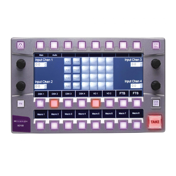
RCP-BR: Guide to Installation and Operation 1 RCP-BR Panel Introduction The highly graphical, touch screen Branding Panel provides highly informative and easy control of Miranda’s channel branding processors, including the Intuition-XG, the Imagestore 750, and the Densite LGK-3901 / DSK-3901 and Imagestore-Modular products. Features... -
Page 10: Setting Up Of The Rcp-Br Panel
These will be explained in this section. Connecting up the panel Please refer to Figure 2-1 for a picture of the rear of the RCP-BR panel. For normal usage an Ethernet cable must be inserted with a connection to the network that the devices to be controlled are on. -
Page 11: Network Configuration
RCP-BR: Guide to Installation and Operation Network configuration The RCP-BR panel comes pre-configured to use DHCP to automatically configure its networking. If a different network configuration is required for the unit then the panel’s Control Window provides the facilities for changing the settings. - Page 12 RCP-BR: Guide to Installation and Operation This will display the dialogue as shown in Error! Reference source not found.. On the touchscreen press the Network button. Figure 2-3 Control window dialogue This will display the network settings as shown in Figure 2-4.
-
Page 13: Station Configuration
RCP-BR: Guide to Installation and Operation Station configuration Before starting to use the RCP-BR panel the station configuration for the unit must be setup. The station configuration defines the devices which the panel should control. These devices could be any of the following: Imagestore 300 •... - Page 14 RCP-BR: Guide to Installation and Operation Please note that increasing the number of channels and devices can slow down RCP-BR operation. The number of devices is limited to 30 and Miranda recommends a maximum of 20 channels. Please contact support@miranda.com you need to create more devices.
-
Page 15: Setting Up The Station Configuration
The station configuration is set up from the RCP-BR’s web interface. Open your preferred web browser and type in the IP address or the hostname of the RCP-BR into the location bar. This will display the login page for the RCP-BR panel as shown in Figure 2-5. - Page 16 RCP-BR: Guide to Installation and Operation Figure 2-6 Web interface home page Selecting the “Station setup” option from the Setup menu will display the page shown in Figure 2-7. Page 8 Miranda Technologies Inc.
- Page 17 Figure 2-7 Station setup page The first operation to carry out is the definition of the devices that will be controlled by the RCP-BR panel. These devices are added in the device area which is on the left of the page.
- Page 18 See Figure 2-9. The device toolbar also contains buttons to edit the properties of existing devices and to delete devices. Note: When configuring an RCP-BR to control “Intuition-XG” units, please select the device type of “Intuition”. Page 10...
- Page 19 RCP-BR: Guide to Installation and Operation On this page the device name and other properties can be defined. Having made the changes to define the device select the ‘Save’ option. This will close the page and return to the main station setup page. You will now see the new device appear in the device area of the page.
- Page 20 RCP-BR: Guide to Installation and Operation Having defined all the devices that are to be controlled by the RCP-BR panel it is then necessary to setup the channels. Devices can then be assigned to appropriate channels. Firstly a new channel should be created by clicking on the ‘Add channel’ option in the channel toolbar as shown in Figure 2-10.
- Page 21 RCP-BR: Guide to Installation and Operation By default, a new channel is created with one “Imagestore” column and one “Intuition” column (columns IS1 and INT1 respectively). Devices from the device area of the page can then be assigned to the new channel: Select the device from the list •...
- Page 22 Figure 2-13 Typical setup of station configuration Having completed the setup of the station configuration, select the Save option in the channel toolbar. This will save the station configuration to the RCP-BR panel. The RCP-BR panel should now be ready for use.
-
Page 23: Using The Rcp-Br Panel
Then insert the DC power supply connector into the unit Then apply AC mains to the power supply unit. The LCD on the RCP-BR panel should initially be off; the LEDs on the bar at the bottom of the unit should gradually change colour from left-to-right to indicate the progress of the unit’s initialisation. -
Page 24: Shutting Down From The System Panel Screen
LEDs going out. The unit must not be turned off until all the LEDs have gone out. To power down the unit the mains supply to the RCP-BR panel power connector must be removed. Do not pull the power connector out of the back of the unit until the shut down process has completed and the mains has been removed from the power connector. -
Page 25: Shutting Down From Small Control Window Dialog
Figure 3-2 System Dialog Starting up an already shut-down RCP-BR unit A RCP-BR that has been shut down, will require the power to be temporarily removed and re-applied by disconnecting the AC mains from the RCP-BR’s power supply unit for 10 seconds and re-applying. -
Page 26: Panel Basics
RCP-BR: Guide to Installation and Operation Panel basics The RCP-BR panel provides three input mechanisms for controlling the selected devices. These are: Physical buttons. These are arranged in three rows with some dedicated buttons and the remainder which change their functionality during operation. -
Page 27: Panel Lock Button
3.4.2 Channel Select When the RCP-BR panel starts up or when the channel select button is pressed the channel selection panel is displayed. This panel allows the operator to select a channel or to gang channels together. This functionality is discussed in detail in section 3.4. -
Page 28: Selecting A Channel
RCP-BR: Guide to Installation and Operation Selecting a channel On start-up or when the CH SEL button is pressed the channel select panel will be displayed. An example of the panel is shown in figure 3-4. Figure 3-4 Channel selection panel The buttons showing Default, Sports and News are groups of channels. - Page 29 The importance of the master channel is that the RCP-BR panel only displays the status of this channel. Indication such as which media is loaded into a channel or which keyers are cut up is based on tallies coming back from this device.
-
Page 30: User Channels
RCP-BR: Guide to Installation and Operation 3.5.2 User channels It is possible for the user to select a subset of ‘user’ channels in the channel selector which are to be controlled by the operator. To do this press the user button as shown in figure 3-6. - Page 31 RCP-BR: Guide to Installation and Operation have been selected the OK button is pressed and the user channel selection panel will be shown with these new channels. Miranda Technologies Inc. Page 23...
-
Page 32: The Main Panel
This channel selector shows all the channels assigned to the ‘user’ channel and will also show any channels which have been selected during the operation of the RCP-BR panel which are not in the ‘user’ selected channels. Page 24... - Page 33 RCP-BR: Guide to Installation and Operation There is also a Hold button to enable channel ganging to be carried out without having to revert to the channel selector panel again. Main panel Figure 3-9 The assignment of keyers shown in this panel will change depending on the configuration of the panel.
-
Page 34: Cutting A Keyer Up Or Down
3.6.1 Cutting a keyer up or down The RCP-BR panel utilises an arm and take mechanism for cutting keyers up or down. This means that multiple events can be triggered simultaneously. To arm a keyer press the keyer button on the middle button bar. The current arm state for the keyer is indicated in the LCD region directly above the keyer button. -
Page 35: Setting Fade Rates
RCP-BR: Guide to Installation and Operation The current state of the keyer is indicated by the button. If the button is lit red then the keyer is currently cut up. Once the keyer is armed, to carry out the armed action, press the ‘Take’ button which will be flashing red to indicate that an item is armed. -
Page 36: Cutting A Voice-Over Up Or Down
3.6.3 Cutting a voice-over up or down The RCP-BR panel utilises an arm and take mechanism for cutting up or down voice-overs. To arm a voice-over press one of the VO buttons on the middle button bar. The current arm state for the keyer is indicated in the LCD region directly above the voice-over button, see figure 3-12. -
Page 37: Macros
3.6.4 Macros The RCP-BR panel utilises an arm and take mechanism for initiating the action of a macro. To arm a macro press one of the macro buttons on the bottom button bar. The current arm state for the macro is indicated in the LCD region directly above the macro button, see figure 3-13. -
Page 38: Fade To Black / Silence
RCP-BR: Guide to Installation and Operation 3.6.5 Fade to black / silence Pressing the Fade button to the right of the macro buttons will display the following panel. Figure 3-14 Fade to black / silence panel From this panel all keyers can be faded to black and/or all voice-overs to silence. -
Page 39: Loading Media Into A Keyer
RCP-BR: Guide to Installation and Operation Loading media into a keyer To load media into a keyer the media browser panel must be displayed. To do this press on either the icon showing the media in the keyer or the DSK arm status label below. - Page 40 RCP-BR: Guide to Installation and Operation Indicator to show that this media is loaded into the keyer Indicator showing which keyer the media selector is working on Figure 3-16 Media Browser panel For most keyers there are three types of media which can be loaded. These are images, animations and scenes.
- Page 41 RCP-BR: Guide to Installation and Operation With any of these exceptions only the allowed options will be accessible in the media browser. To select an item from the media browser to load into the keyer just press on the icon on the touchscreen. The background for the icon will initially turn amber to indicate that the media is loading and then turn green to indicate that the media is loaded into the keyer.
-
Page 42: Filter
RCP-BR: Guide to Installation and Operation 3.7.1 Filter On devices with a lot of media it is possible to enter a search string so that only the media containing this string shall be displayed in the browser. To enter the string press the button above the label marked ‘Filter’. - Page 43 RCP-BR: Guide to Installation and Operation When a search string is active, it is shown at the bottom of the media browser panel as shown in figure 3-19. Current filter string shown here. Figure 3-19 Media panel showing filter string Once a filter string has been entered this will be retained if the media browser changes to browse media of another type.
-
Page 44: Modifying Media In A Keyer
RCP-BR: Guide to Installation and Operation Modifying media in a keyer The following modifications can be made to media in a keyer: Position. Cropping. Clip, gain and transparency. To modify the media select the button above the ‘Setup’ label in the media browser panel. -
Page 45: Adjusting The Media Cropping
The cropping of the media can be adjusted using all of the rotary controls on the RCP-BR panel. As the cropping is adjusted using these controls, the extent of the cropping on the media will be shown in the preview screen in the middle of the panel. -
Page 46: Adjusting The Media Clip, Gain And Transparency
RCP-BR: Guide to Installation and Operation button will also save any changes made to the media position or clip, gain and transparency. 3.8.3 Adjusting the media clip, gain and transparency To adjust the clip, gain and transparency of the media press the button above the CGT label in either the Setup or Crop panels. -
Page 47: Audio
RCP-BR: Guide to Installation and Operation Audio The Audio panel is displayed when the ‘Audio’ button is pressed or the audio meters are pressed on the touchscreen in the main panel. This Audio button will only be available if the device in the channel is an Imagestore. The audio panel is shown in figure 3-23. - Page 48 RCP-BR: Guide to Installation and Operation To adjust the audio input settings press the button above the Input label. This will display the audio input panel as shown in figure 3-24. Figure 3-24 Audio input setup The rotaries are used to adjust the audio input levels for each of the four input channels.
-
Page 49: Voice-Overs
RCP-BR: Guide to Installation and Operation Voice-overs The current voice-over status is shown in the main panel as shown in figure 3-25. Figure 3-25 Voice-over status indications on main panel The voice-over graph shows a representation of the preset and duck levels currently configured for each voice-over. -
Page 50: Easyplay Media Browsing
The voice-over input shuffle can be adjusted using the voice-over shuffle control. 3.9.1 Easyplay media browsing If the RCP-BR panel is connected to an Imagestore 750 or LGK-3901 device running software version 3.1.3 or later, then the option to browse for audio media is also available. - Page 51 RCP-BR: Guide to Installation and Operation If Easyplay is configured to be available on both Program and Preview outputs then the “Play Preview” and “Load Preview Only” options are available. These allow media to be loaded and played only on the Preview output of the controlled Imagestore 750 / LGK-3901 device, without affecting the Program output.
-
Page 52: 3.10 The System Panel
Figure 3-28 System panel If the System label is lit red, it indicates that one of the devices configured on the RCP-BR panel is alarmed. To find out which device is alarmed press the ‘Alarms’ button within the System panel. - Page 53 Access the Windows task manager. View the web interface connected to the RCP-BR panel. Restart or shutdown the RCP-BR. Please note that these can be carried out directly from the System panel. To close the control window press any area of the touchscreen outside the control window.
-
Page 54: 3.11 Alarms
RCP-BR: Guide to Installation and Operation 3.11 Alarms Pressing the ‘Alarms’ button in the System panel will display the Alarms panel. Figure 3-31 Alarms panel The panel shows the device alarms for the Imagestore, LGK or DSK device for the current channel. If multiple channels are ganged, then the alarms for the master channel are shown (see section on Channel ganging for more details). -
Page 55: The Web Interface
To access the web interface start-up a web browser on a computer that has network access to the RCP-BR panel. Type in the IP address or the hostname of the RCP-BR panel into the location bar of the browser. This will display the login page for the RCP-BR panel as shown in figure 4-1. - Page 56 RCP-BR: Guide to Installation and Operation Figure 4-2 Web interface home page The web interface home page shows the information about the RCP-BR panel: The current software version. • The serial number if one is defined. • The date that the software was last updated.
-
Page 57: Maintenance
RCP-BR: Guide to Installation and Operation Maintenance The maintenance option in the web interface allows for the following actions: Update software • Show update history • Licenses • Install panels • System restart • System shutdown • Figure 4-3 The web interface maintenance options To display the drop down list of options move the mouse to point to the ‘Maintenance’... -
Page 58: Update
This will initiate the update of the RCP-BR panel. It is important to note that once the update button is pressed there will be a long delay whilst the process of updating the RCP-BR panel is carried out. At the end of the update process the RCP-BR panel will automatically restart. -
Page 59: Update History
If any of the ‘Release notes’ buttons are pressed then a window showing the appropriate release notes for the RCP-BR will be displayed. If the ‘Log’ button is pressed then the log for installation process associated with the release is shown. -
Page 60: Licenses
RCP-BR: Guide to Installation and Operation 4.1.3 Licenses This page displays the licenses that are currently installed on the RCP-BR unit. Please contact customer support with the Customer Id displayed on this page if you require additional licenses. Figure 4-6 Licenses Page 52 Miranda Technologies Inc. -
Page 61: Install Panels
RCP-BR panel. These panels will not automatically replace the panels on the RCP-BR panel as these have the ability to be modified by the user. To update to the latest panels installed on the RCP-BR panels select the option ‘Install panels’. -
Page 62: System Restart
RCP-BR: Guide to Installation and Operation 4.1.5 System restart It is possible to restart the RCP-BR panel from the web interface. To restart the unit select ‘System Restart’ from the drop down list. Figure 4-8 RCP-BR panel restart To restart the unit press the ‘Restart’ button. -
Page 63: System Shutdown
RCP-BR: Guide to Installation and Operation 4.1.6 System shutdown To shutdown the RCP-BR panel from the web interface select the ‘System shutdown’ option from the maintenance drop down list. This will show the shutdown page of the web interface. Figure 4-9 RCP-BR panel shutdown To shutdown the RCP-BR panel press the ‘Shutdown’... -
Page 64: Diagnostics
RCP-BR: Guide to Installation and Operation Diagnostics The diagnostics section of the web interface allows for the following diagnostic operations to be carried out: Retrieve log files. Watch log. Show running processes. Download diagnostic zip file To select the diagnostic option point the mouse at the ‘Diagnostics’ box. This will show the drop down shown in figure 4-10. -
Page 65: Retrieve Log Files
Retrieve log files Selecting the ‘Retrieve log files’ option allows a selection of the log files on the unit to be selected for download. The log files on the RCP-BR panel are displayed in a list as shown in figure 4-11. - Page 66 RCP-BR: Guide to Installation and Operation To select the log files to download click in the box at the left side of the log file name. This will display a green tick in the box. Having selected all the log files which are required for download press the ‘Download’...
-
Page 67: Watch Log
Watch log Selecting the ‘Watch log’ option from the diagnostic list will show a live updating list of the log file from the RCP-BR panel as shown in figure 4-13. Figure 4-13 Watch log By default the Xpanel logs are shown, but the XMS logs can also be watched. -
Page 68: Running Processes
4.2.3 Running processes By selecting the running processes option from the diagnostics list a continuously updating display of the current processes on the RCP-BR panel is shown. Figure 4-14 Display of running processes on RCP-BR panel Page 60 Miranda Technologies Inc. -
Page 69: Setup
RCP-BR: Guide to Installation and Operation Setup The web interface Setup option allows the setup of the following features: Network • Hostname • Time • Mouse • Serial number • Station • To select the Setup option point the mouse at the ‘Setup’ box. This will drop down the Setup list as shown in figure 4-15. -
Page 70: Network Setup
‘DHCP’ or ‘Static’ radio buttons and then enter the IP Address, Subnet Mask and Default Gateway. Having carried out the appropriate changes press the ‘Apply’ button to update the network on the RCP-BR panel. It is not necessary to restart the RCP-BR panel for these settings to come into effect. -
Page 71: Set Hostname
RCP-BR: Guide to Installation and Operation 4.3.2 Set hostname Selecting the ‘Set hostname’ option from the setup list allows the hostname of the RCP-BR panel to be changed. Figure 4-17 Changing the RCP-BR hostname The new hostname can be typed into the text box and then the ‘Apply’ button is pressed. -
Page 72: Time Setup
Figure 4-18 Setup of time and date on the RCP-BR panel When the date, time and time zone values have been setup correctly, press the ‘Apply’ button. When this change is made the time and date on the RCP-BR panel will be updated without the requirement to restart the unit. -
Page 73: Mouse Setup
4.3.4 Mouse setup By default the mouse pointer on the RCP-BR panel is turned off. If it is required to display the mouse then this can be enabled in the ‘Mouse setup’ page. Figure 4-19 Mouse pointer show/hide on the RCP-BR panel The mouse pointer will be turned on or off as soon as the ‘Show’... -
Page 74: Serial Number
Figure 4-20 Display of the RCP-BR panel serial number 4.3.6 Station Station setup is an essential step in getting an RCP-BR panel configured for operation. As a result, this operation is covered earlier in section 2.3. Page 66 Miranda Technologies Inc. -
Page 75: Installation
RCP-BR unit. Mounting RCP-BR ships with both “ears” and “30 degree desk-mounting” brackets. Also available and sold separately: Rack-mount kit ( order code RCP-BR-RM-KIT, for 19” rack mounting ) • Desk-mount kit ( RCP-BR-DM-KIT, desk-mounting 60 degree brackets) • 5.1.1... - Page 76 RCP-BR: Guide to Installation and Operation Figure 5-5-2 Mounted with ears Page 68 Miranda Technologies Inc.
-
Page 77: Mounting With 30 Degree Brackets
RCP-BR: Guide to Installation and Operation 5.1.2 Mounting with 30 degree brackets Figure 5-5-3 Mounting with 30 degree bracket Figure 5-5-4 Mounted with 30 degree bracket Miranda Technologies Inc. Page 69... -
Page 78: With 60 Degree Desk-Mounting Kit, Rcp-Br-Dm-Kit
RCP-BR: Guide to Installation and Operation 5.1.3 With 60 degree Desk-Mounting kit, RCP-BR-DM-KIT The 60 degree Desk-Mounting Kit is sold separately - order RCP-BR-DM-KIT Figure 5-5-5 Mounting with 60 degree Desk-Mounting Kit - assembly Figure 5-5-6 Mounted with 60 degree Desk-Mounting kit Page 70 Miranda Technologies Inc. -
Page 79: With Rack-Mounting Kit, Rcp-Br-Rm-Kit
RCP-BR: Guide to Installation and Operation 5.1.4 With Rack-Mounting kit, RCP-BR-RM-KIT The Rack-Mounting Kit is sold separately – order code RCP-BR-RM-KIT Figure 5-5-7 Mounting with Rack-Mounting kit - assembly Figure 5-5-8 Rack-Mounted Miranda Technologies Inc. Page 71... -
Page 80: Ventilation
RCP-BR: Guide to Installation and Operation Ventilation The RCP-BR unit is forced-air cooled. Air is drawn into the unit through holes at the rear of the unit. Air is exhausted through holes both at the rear and along one side of the unit. -
Page 81: Rcp-Br Rear Connections
RCP-BR: Guide to Installation and Operation RCP-BR rear connections 5.4.1 Summary The RCP-BR rear connections are: Name Connector Description Metal earthing stud DC power 8-pin DIN DC power, 12V from supplied power adapter GPIO 15 way D-type This is not a VGA connector 4 opto-coupled GPI in/out* * For later implementation. -
Page 82: Dc Power Connector Pinout (8 Pin Din, Female)
RCP-BR: Guide to Installation and Operation 5.4.2 DC power connector pinout (8 pin DIN, female) The connector on the rear of the RCP-BR unit is: Pin Number Pin function +12V +12V +12V +12V Diagram of the DC power cable and cable connector of the power adapter... -
Page 83: Gpio Pinout (15-Way D-Type)
GPIO 2 GPIO 3 GPIO 4 5,6,7,8 Ground Return GPI +5V power, 500mA max, internally fused 10-15 Reserved Recommend use of Miranda NSH15M 15way terminal adapter with this connector. This is NOT a VGA connector Miranda Technologies Inc. Page 75... -
Page 84: Mechanical
RCP-BR: Guide to Installation and Operation Mechanical The RCP-BR unit is a ½ rack-width, 3RU 19” rack unit. It comes with rack mounting ears and 30 degree mounting brackets. Main unit dimensions: Height : 135mm approx. • Width : 220mm approx. ( excluding “ears” ) •... -
Page 85: Other
Other 5.7.1 RTC battery The RCP-BR contains a back-up cell battery (3V CR2032 or equivalent ) for the Real Time Clock and CMOS settings. Should this need replacing, contact Miranda Customer Support and dispose of depleted battery in accordance with local regulations.
Need help?
Do you have a question about the RCP-BR and is the answer not in the manual?
Questions and answers