
Subscribe to Our Youtube Channel
Related Manuals for Miranda iMC-Panel-200


Summary of Contents for Miranda iMC-Panel-200
- Page 1 MCS Panel Confi guration Editor Confi guration Tool for iMC Master Control Panels User’s Guide UG0066-01 7 Nov 2012...
- Page 2 The information and intellectual property contained herein is confidential between Miranda and the client and remains the exclusive property of Miranda. If you find any problems in the documentation, please report them to us in writing. Miranda does not warrant that this document is error-free.
- Page 3 Restriction on Hazardous Substances (RoHs) Miranda is in compliance with EU Directive RoHS 2002/95/EC governing the restricted use of certain hazardous substances and materials in products and in our manufacturing processes.
- Page 4 The fuse symbol indicates that the fuse referenced in the text must be replaced with one having the ratings indicated. The presence of this symbol in or on Miranda equipment means that it has been designed, tested and certified as complying with applicable Underwriter’s Labora- tory (USA) regulations and recommendations.
- Page 5 MCS Panel Configuration Editor User’s Guide General Cautions A caution indicates a possible hazard to equipment that could result in equipment damage. Observe the following cautions when operating or working on this equipment: • When installing this equipment, do not attach the power cord to building surfaces. •...
-
Page 7: Table Of Contents
Other Miranda Products ........ - Page 8 Touchscreen ........
- Page 9 MCS Panel Configuration Editor User’s Guide FECP Summary................. 56 FECP Buttons .
- Page 10 Table of Contents 4 Editor Basics ......... . 83 Editor Overview.
- Page 11 MCS Panel Configuration Editor User’s Guide PST Unselected Source Color ............. 118 ‘Automation Off’...
- Page 12 Table of Contents Audio Macros ................148 Live Levels .
- Page 13 MCS Panel Configuration Editor User’s Guide 8 Button Functions (for Imagestore 750s) ....181 Summary ..................181 Definable Button Functions .
- Page 14 Table of Contents...
-
Page 15: Preface
Preface Chapter 1 is an introduction to the MCS Panel Configuration Editor User’s Guide. Topics Chapter Structure ............... . . 1 The PDF Document . -
Page 16: The Pdf Document
(modified). FECP full-size enhanced control panel. iMC-Panel-300 full-size control panel, based on the FECP. iMC-Panel-200 compact control panel, based on the CECP. iMC-Panel-100 rack-mount control panel, based on the SCP. iMC-Panel-GUI software control panel, based on the CECP GUI. -
Page 17: Prerequisites
Xbuilder and Xstudio are creative software applications under XMedia. • Oxtel is a division of Miranda. Its name is used to identify certain ports of the Intuition XG hardware. The Oxtel protocol is used by the Imagestore 750 in the master control system. -
Page 18: Options
Then read carefully only the sections you need to read, one at a time. If you intend to use the Intuition XG component of master control, please obtain Intuition docu- mentation from Miranda. - Page 19 MCS Panel Configuration Editor User’s Guide If you incorporate Imagestore 750s in your system, please obtain the Imagestore 750 User Manual from Miranda. (The Master Control Reference Manual has a brief description of the Imag- estore 750 if you need a quick tutorial.)
- Page 20 Preface How to Use This Manual...
-
Page 21: Introduction
Imagestore 750. Master Control System Overview Miranda’s master control system — a multi-channel switcher — might include one or more MCEs or MCPMs in NV5100MC frames and one or more Imagestore 750s. The frames are 8RU assem- blies that have 16 I/O card slots that can operate in conjunction with other switchers, routers, an NV9000 router control system, and other products. -
Page 22: Nv9000 Router Control System
Introduction Introduction Transition processors (MCPMs, MCEs, and Imagestore 750s) and control panels communicate on an Ethernet LAN. When an operator presses control panel buttons (the ‘Transition’ button, for example), the control panel issues commands to a transition processor. The transition processor responds with status and (unless a problem exists) executes the command. -
Page 23: Control Panels
A software control panel. This panel also runs on a PC and has a graphical user interface. This GUI is a software emulation of the iMC-Panel-200. This GUI is designed to operate with (or without) a touch-sensitive screen. iMC-Panel-100 A 3RU rack-mounted panel with a separate rack-mountable touchscreen display. -
Page 24: Transition Processors
Introduction Introduction NV5100MC-FECP FECP, or “full-size” enhanced control panel. The FECP mounts on a desktop or work surface. All but 2 buttons have LCD legends and color- coding. NV5100MC-SCP SCP, or simple control panel. The SCP is a 3RU rack-mount unit. Although it has function buttons and audio control knobs, it has no touchscreen: the menu items are encoded in the button legends. -
Page 25: Other Miranda Products
Listed here are products that relate to master control. Tally Processor Miranda offers a third-party “tally processor”— a 1RU device that provides 32 optically isolated inputs and 32 relay outputs, also optically isolated. Through Miranda’s NVISION Ethernet protocol (NVEP), the tally processor can sense master control events such as main source selec- tions and transitions and trigger master control events. -
Page 26: Mcpm Overview
There is an ‘Int XG’ button and a ‘Preview Int XG’ button on the main menu of the iMC-Panel-100, iMC-Panel-200, CECP, CECP M1, iMC-Panel-300, FECP, iMC-Panel-GUI, and CECP GUI. Each causes a menu of Intuition XG key layers to be displayed. These control panels might also have ‘XG layer’... -
Page 27: Video Effects And Audio Overs
MCS Panel Configuration Editor User’s Guide Video Effects and Audio Overs Video effects include: keyer 1, logo A, squeezeback, keyer 2, keyer 3, logo B. The MCPM applies video effects, layered cumulatively, to the selected main source (preset or program) in the order listed above. A key is a video overlay. -
Page 28: Mcpm Types
Introduction Introduction MCPM Types There are 7 MCPM types: MCPM-SD MCPM-MK-SD (“Mixer/Keyer”) MCPM-SDHD MCPM-HD MCPM-MK-HD (“Mixer/Keyer”) MCPM-HD2 All MCPMs have common characteristics, such as audio meter outputs, GPIO, clean-feed outputs, and emergency bypass capability, but also have many differences. The mixer/keyers do not have squeezeback and have one logo inserter (logo B). The MCPM- SDHD provides enhanced squeezeback. -
Page 29: Mce Summary
MCS Panel Configuration Editor User’s Guide MCE Summary MCEs (master control engines) are the “next generation” of MCPMs — devices that perform master control switching and mixing. Not all features of the MCE product line are available yet. The MCE is an extendable product, occupying up to 3 card slots, with a full set of features. There are 4 modules in the MCE card set: •... -
Page 30: Machine Control
Introduction Introduction Figure 2-3 shows the front of one of 4 possible MCE assemblies and its associated backplanes: MCE AXM MCE PVW Program Out Bypass In Dolby E Metadata Preset Out Outputs 1–8 Preview Out, Clean-Feed Out, A & B A &... -
Page 31: Imagestore 750 Summary
(also called a “channel branding processor”) that can operate as a stand-alone unit with or without automation, or as part of Miranda’s iMC master control system. In the context of the combined master control system, it operates in conjunction with an NV9000 router control system that provides video and audio sources and one or more master control panels, such as the iMC-Panel-200, that provide commands. -
Page 32: Conceptual Model
Introduction Introduction Conceptual Model This diagram shows the Imagestore 750’s native conceptual model: (option) DVE 1 Video DVE2 DSK 1 DSK 2 DSK 3 DSK 4 Program Mixer Output (option) DVE 1 DVE2 DSK 1 DSK 2 DSK 3 DSK 4 Preview Video Output... -
Page 33: Nv9000'S Ip Address
MCS Panel Configuration Editor User’s Guide A certain version of the Imagestore 750 configuration software is required to support these features. That version is v1.4 at present. Note that in the master control system, the “PGM bus” is the name of an element in an MCE or MCPM. -
Page 34: Fill And Key
Because the iMC-Panel-200 and iMC-Panel-GUI have potentially 16 source buttons and the iMC- Panel-300 has potentially 24 source buttons, up to 24 NV9000 destinations may be reserved for the monitor wall. -
Page 35: Configuration Editor Overview
MCS Panel Configuration Editor User’s Guide In “PresStation mode, ” the preset row’s DSK, DVE, and voice-over buttons light when they are armed (for the next transition) and are dimmed when they are disarmed. In the “traditional mode, ” the DSK, DVE, and voice-over buttons light when the actively contribute to the preset video output and are dimmed when they do not contribute, regardless of whether they are armed. - Page 36 Introduction Introduction...
-
Page 37: Control Panels
............... . 24 iMC-Panel-200 Summary . -
Page 38: Panel Comparison
The iMC-Panel-100 was derived from the SCP and has an added display. The iMC-Panel-GUI was derived from the CECP GUI. The iMC-Panel-200 and the CECP share configuration pages in the configuration editor. The iMC-Panel-300 and the FECP share configuration pages in the configuration editor. -
Page 39: Imc-Panel-200 Summary
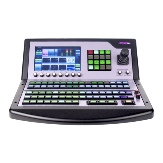
User’s Guide iMC-Panel-200 Summary The iMC-Panel-200 is a configurable master control panel, 19.7″ wide × 6.96″ high × 20.21″ deep. Rear connectors extend the depth 0.67″. The iMC-Panel-200 requires at least 2–3″ clear- ance at the rear for cables. The iMC-Panel-200 sits on a console or desktop. - Page 40 176. 3 Aux/user buttons The iMC-Panel-200 has 16 aux/user buttons. The functions of the buttons differ when the panel is controlling an MCE or MCPM or an Imagestore 750. This button row contains aux and aux delegate buttons when the panel is controlling an MCE and contains aux and customer-definable function buttons when the panel is controlling an Imagestore 750.
- Page 41 MCS Panel Configuration Editor User’s Guide For MCEs, the aux buttons consist of the same main sources that appear on the preset, pro- gram, and preview buses plus up to 6 “aux delegate” buttons. The different delegate buttons determine the function of the aux bus. The aux bus might or might not be related to the aux outputs of an MCE, depending on configuration.
-
Page 42: Imc-Panel-200 Buttons
(page 164, for Imagestore 750s). 11 System control buttons There are 3 buttons in the system control section of the iMC-Panel-200. Their functions differ when the panel is controlling an MCE or MCPM or an Imagestore 750. See Bottom Row Lay-... -
Page 43: Imc-Panel-200 Knobs
2 Pressing a selected button has no effect: the button remains selected. iMC-Panel-200 Knobs Turning a knob clockwise increases the associated value until the maximum value is reached. Turning the knob counter-clockwise decreases the associated value until the minimum value is reached. -
Page 44: Imagestore 750
The touchscreen provide scroll bars for list selection. iMC-Panel-200 Connectors At the rear of the iMC-Panel-200 are 2 power connectors, one Ethernet connector, a USB port, a fan, an aux port, a GPI/alarm connector, and an audio metering input: Fig. 3-2: iMC-Panel-200 (rear view) The USB port and the aux port are reserved for future development. -
Page 45: Gpi/Alarm
Major Alarm GPI Out 2 unused GPI In 2 – Refer to the GPI section in one of the two iMC-Panel-200 operator’s guides for connection infor- mation. Also see Panel GPI on page 193. Audio Metering Input The audio metering output of an MCE is a suitable source for this input. - Page 46 Control Panels Control Panels Figure 3-3 shows the location of the iMC-Panel-300’s touchscreen, function buttons, and controls: Fig. 3-3: Sections of the FECP (Shown Controlling an Imagestore 750) Sections of the iMC-Panel-300 Configurable buttons Preview/user buttons Touchscreen Aux/user buttons Joystick Program and preset “layer”...
-
Page 47: Imc-Panel-300 Buttons
MCS Panel Configuration Editor User’s Guide iMC-Panel-300 Buttons Panel buttons are large and appear in several colors (green, amber, red, blue, white, violet, and aqua) and 3 brightness levels: off, low-tally, and high-tally. They are dynamically re-legendable, displaying 3 lines of text, 8 characters per line. (The text might be blank.) In addition to these colors, a button can be dark (that is, off, or having no color). -
Page 48: Imagestore 750
Control Panels Control Panels • Select a video effect and alter its settings. • Manipulate audio. • Change transition rates. • Perform panel maintenance and updates. • View status and error messages. • View “live levels” (MCEs only). The touchscreen provides scroll bars for list selection. Imagestore 750 For Imagestore 750s, the touchscreen lets operators do the following: •... - Page 49 MCS Panel Configuration Editor User’s Guide Associated with the touchscreen are 8 rotary knobs for adjustment of parameters. Not all knobs are active all the time. When a knob is active, the touchscreen shows a colored indica- tor near the knob. 3 Joystick The use of the joystick differs when the panel is controlling an MCE or MCPM or an Imag- estore 750.
- Page 50 Control Panels Control Panels 6 Program and preset sources The iMC-Panel-300 has 24 program buttons and 24 preset buttons. The functions of the but- tons differ when the panel is controlling an MCE or MCPM or an Imagestore 750. For MCEs and MCPMs: The 24 program buttons includes up to 16 main source buttons (at the left) and up to 12 “layer”...
-
Page 51: Imc-Panel-300 Connectors
MCS Panel Configuration Editor User’s Guide For MCEs, the aux/user buttons consist of the same main sources that appear on the preset, program, and preview buses plus up to 6 “aux delegate” buttons. The different delegate but- tons determine the function of the aux bus. The aux bus might or might not be related to the aux outputs of an MCE, depending on configuration. -
Page 52: Ethernet
Control Panels Control Panels Ethernet The iMC-Panel-300 has one RJ-45 Ethernet port. The iMC-Panel-300 connects to the Ethernet switch of the master control network. It is on this network that the iMC-Panel-300 communicates with MCPMs and with the configura- tion software. You (or your system administrator) must provide a unique IP address for the iMC- Panel-300. -
Page 53: Imc-Panel-100 Summary
(19.0″ wide × 5.22″ high × 3.70″ deep) and (2) a customer-supplied monitor. This is a front view of the button panel: Miranda provides support for the Planar series of touchscreens. This is the Planar PT1945R: It has a removable stand and can be wall-mounted. Other VGA monitors can be used. If your choice of a monitor is not a touchscreen, an operator can use a mouse to select items on the screen. - Page 54 Control Panels Control Panels Figure 3-1 shows the location of the iMC-Panel-100’s touchscreen, function buttons, and controls. Display Button Panel Fig. 3-5: Sections of the iMC-Panel-100 (Shown Controlling an Imagestore 750) Top row buttons Aux/user buttons Bottom row buttons Menu area Preview/user buttons ‘Scroll/Set’...
- Page 55 MCS Panel Configuration Editor User’s Guide Following are brief descriptions of each section: 1 Top row buttons The 8 large buttons in this row are all customer-configurable buttons. However, the row is designed to accommodate channel selection buttons that have thumbnail images representing the channels.
-
Page 56: Imc-Panel-100 Buttons
Control Panels Control Panels The preset buttons include main source buttons and “layer” buttons. In fact, the preset bus and program bus have the same button functions. The function assigned to a program but- ton is also assigned to the preset button directly beneath it. Whatever main source, video effects, and voice-overs are selected on the preset bus form the preview output of the Imagestore 750 that is currently controlled by the panel. -
Page 57: Imc-Panel-100 Knobs
MCS Panel Configuration Editor User’s Guide Panel buttons are large and appear in several colors (green, amber, red, blue, white, violet, and aqua) and 3 brightness levels: off, low-tally, and high-tally. They are dynamically re-legendable, displaying 3 lines of text, 8 characters per line. (The text might be blank.) In addition to these colors, a button can be dark (that is, off, or having no color). -
Page 58: Imagestore 750
Control Panels Control Panels Imagestore 750 For Imagestore 750s, the touchscreen lets operators do the following: • Select a main source. • Select a downstream keyer (DSK) and alter its settings. • Select a DVE and alter its settings. • Arm or “fire”... -
Page 59: Power
The iMC-Panel-GUI is a software control panel that runs on a PC connected to the master control network. It emulates the functions of the iMC-Panel-200. Its menu section emulates the touchscreen menu of the iMC-Panel-200. The GUI can be oper- ated either with a mouse on any PC or by finger pressure on a touchscreen PC. - Page 60 Control Panels Control Panels Figure 3-7 identifies the sections of an iMC-Panel-GUI that is controlling an MCE: Menu Slider Configurable Buttons Audio Section Menu “Knobs” Sources Delegates Preview Preview Sources Layers Program Program Sources Layers Preset Preset Layers Sources Transition Control System Control Transition Button Fig.
-
Page 61: Gui Buttons
MCS Panel Configuration Editor User’s Guide Figure 3-8 identifies the sections of the iMC-Panel-GUI that is controlling an Imagestore 750: Menu Slider Configurable Buttons Menu “Knobs” Configurable Sources Buttons (up to Config- Configurable urable But- Buttons Program and Program Preset Layers and Pre- ()up to 7) Sources... -
Page 62: Knobs And Slider
Control Panels Control Panels This GUI’s “Transition” button is at the lower right and it is usually orange. It is red during a pre- roll transition. Knobs and Slider The GUI has knob “proxies” and a slider with which operators may change parameter values. The menu is associated with 8 knob proxies. - Page 63 MCS Panel Configuration Editor User’s Guide The preset buttons allows you to set up the state of the program output that will exist after the next transition. The preset bus, program bus, and preview bus all have the same button functions. (See Bank Select on page 144.)
-
Page 64: Other Features
Control Panels Control Panels 6 Transition control buttons The 8 buttons in this section are, by default, transition buttons, but they are also config- urable. The functions of these buttons differ when the panel is controlling an MCE or MCPM or an Imagestore 750. - Page 65 MCS Panel Configuration Editor User’s Guide Figure 3-1 shows the location of the CECP’s touchscreen, function buttons, and controls. Fig. 3-9: Sections of the CECP Sections of the CECP Program buttons Preset buttons Preview buttons Aux buttons LCD touchscreen Configurable buttons Joystick Touchscreen knobs Audio monitor knobs...
- Page 66 Control Panels Control Panels 2 Preset buttons The preset bus allows you to set up the state of the program output that will exist after the next transition. The preset bus the same button definitions as the program bus. 3 Preview buttons The preview bus allows a master control operator to experiment with main sources and video effects without interfering with on-air programming or with automation.
-
Page 67: Cecp Buttons
MCS Panel Configuration Editor User’s Guide 11 Transition control buttons The 8 buttons in this section are, by default, transition buttons, but they are also config- urable. 12 System control buttons There are 3 buttons in the system control section of the CECP. They are ‘Panel Lock’ , ‘Auto Off’ , and ‘Fade to Black’... -
Page 68: Cecp Knobs
Control Panels Control Panels CECP Knobs Turning a knob clockwise increases the associated value until the maximum value is reached. Turning the knob counter-clockwise decreases the associated value until the minimum value is reached. Turning the knob beyond its value limits has no effect. An indicator on the touchscreen illuminates just above any of the 8 touchscreen knobs when it is enabled. -
Page 69: Power
MCS Panel Configuration Editor User’s Guide Power There are 2 AC connectors, PS1 and PS2, for redundancy. You need not use both if you are not concerned with redundancy. Ethernet The CECP has one RJ-45 Ethernet port. The CECP connects to the Ethernet switch of the master control network. -
Page 70: Fecp Summary
Control Panels Control Panels FECP Summary The FECP is a configurable master control panel, 28.25″ wide × 6.96″ high × 20.14″ deep. It has only one mounting option: it sits on a console or desk top. Arrayed on the panel are 140 color-coded LCD buttons, a touchscreen menu (LCD) with 8 associ- ated control knobs, 2 white toggle buttons, 4 audio knobs (a.k.a. -
Page 71: Fecp Buttons
MCS Panel Configuration Editor User’s Guide Sections of the FECP Customer-programmable buttons Aux buttons Touchscreen menu Program, preset, and preview “layer” buttons Joystick Transition control buttons Audio monitor/meter control System control buttons Program audio control Transition button Program, preset, and preview sources At the rear of the panel are 2 power connections, an Ethernet port, a USB port, an aux port, and a GPI/alarm connector (DB25), and an audio metering input. -
Page 72: Fecp Knobs
Control Panels Control Panels Some buttons are toggles. Pressing a deselected toggle button will cause it to become selected. Pressing a selected toggle button will make it deselected. Some groups of buttons operate as a mutually exclusive set. Pressing a deselected button will cause it to become selected and all other buttons in the set to become deselected. - Page 73 MCS Panel Configuration Editor User’s Guide 2 Touchscreen menu Using the color LCD touchscreen, you can access all secondary system functions such as key setups, squeezeback presets and audio settings. Associated with the touchscreen are 8 rotary knobs for selection and adjustment of parameters. 3 Joystick The joystick allows fine visual adjustment of squeezeback images for the MCPM-SDHD and MCEs.
-
Page 74: Fecp Connectors
Control Panels Control Panels The preview bus is enabled (active) only when the FECP controls an MCE. 9 Transition control buttons The 12 transition control buttons include breakaway buttons, transition types, and transition rates, by default. (The actual rates are configured in the MCPM.) These buttons are config- urable. -
Page 75: Audio Metering Input
MCS Panel Configuration Editor User’s Guide Refer to the GPI section in the FECP Operator’s Guide for connection information. Also see Panel GPI on page 193. Audio Metering Input The ‘SD/HD Input’ connector (BNC) is the panel’s audio metering input. This input drives the panel’s “live levels”... -
Page 76: Gui Buttons
Control Panels Control Panels Figure 3-18 identifies the sections of the CECP GUI: Menu Slider Configurable Buttons Audio Section Menu “Knobs” Aux Dele- Sources gates Preview Preview Sources Layers Program Program Sources Layers Preset Preset Layers Sources Transition Control System Control Transition Button Fig. -
Page 77: Knobs And Slider
MCS Panel Configuration Editor User’s Guide Some groups of buttons operate as a mutually exclusive set. Pressing a deselected button will cause it to become selected and all other buttons in the set to become deselected. There are two types of mutually exclusive buttons: 1 Pressing a selected button makes it deselected. -
Page 78: Other Features
Control Panels Control Panels Some MCPMs do not support all video effects. Only MCEs support XG keyer layers. Whatever main source, video effects, audio overs, and XG keyer layers are selected on the program bus form the program output of the MCPM that is currently controlled by the GUI. (See Bank Select on page 144.) - Page 79 MCS Panel Configuration Editor User’s Guide Arrayed on the front of the panel are 48 color-coded LCD buttons, a touchscreen LCD with 4 associated control knobs, 27 white toggle buttons, and 5 audio knobs (a.k.a. rotary encoders). Each LCD button shows 2 lines of text, 4 characters per line. The LCD buttons are either “green, ” “amber, ”...
-
Page 80: Cfcp Buttons
Control Panels Control Panels At the rear of the panel are 2 power connections, 2 Ethernet ports, a ‘CP Aux’ connector (DB15) used for the optional TLA, and a GPI/alarm connector (DB25). Power Connectors Aux Connector (for TLA) Ground Lug Ethernet Connector GPI/Alarms Connectors Fig. - Page 81 MCS Panel Configuration Editor User’s Guide 1 Customer-programmable buttons The customer-programmable section includes 16 function buttons. Each may be pro- grammed to perform functions such as channel selection, GPIO, or transition control. Because the CFCP has fewer physical buttons than the FFCP, it has these extra functions: •...
-
Page 82: Cfcp Connectors
Control Panels Control Panels and fade-cut. There are 3 transition rates: slow, medium, and fast. (The actual rates are con- figured in the current MCPM or MCE.) 8 System control button. The system control button is ‘Panel Lock’ by default, but it can be configured for some other function. -
Page 83: Ffcp Summary
MCS Panel Configuration Editor User’s Guide FFCP Summary The FFCP is a console-mounted master control panel. It can simply rest on a desktop or flat surface, or it can be recessed into the desktop. It is 29″ wide and about 15″ deep. The FFCP does not support Imagestore 750 transition processors. -
Page 84: Ffcp Buttons
Control Panels Control Panels FFCP Buttons LCD buttons are large and appear in 3 colors (green, amber, and red) and 3 brightness levels: off, low-tally, and high-tally. They are dynamically re-legendable, displaying 2 lines of text, 4 charac- ters each. (The text might be blank.) LCD buttons allow you to choose sources, options, video effects, and audio overs. -
Page 85: Ffcp Connectors
MCS Panel Configuration Editor User’s Guide The audio level section includes 3 rotary knobs for adjusting the output level of the source selected on preset or program, and the over/main ratio for preset or program. 5 Program/preset buttons The program and preset “buses” include two rows of 16 buttons used for audio and video source selections and two rows of 8 “layer”... -
Page 86: Gpi/Alarm
Control Panels Control Panels GPI/Alarm The FFCP has a DB25 connector that supports GPI inputs, GPI outputs, and alarms: GPI In 1 GPI Out 1 – Minor Alarm unused Major Alarm GPI Out 2 unused GPI In 2 – Refer to the GPI section in the FFCP Operator’s Guide for connection information. See Panel GPI on page 193 for more information. -
Page 87: Gui Buttons
MCS Panel Configuration Editor User’s Guide Figure 3-18 identifies the sections of the PC GUI: Menu Menu Arrows Audio Section Customer- Programmable Buttons Program Program Layers Sources Preset Preset Layers Sources System Buttons Breakaway Control Transition Types Transition Rates Transition Button Fig. -
Page 88: Absence Of Knobs
Control Panels Control Panels The GUI has a central system of menu buttons. It is through the menu that you can adjust oper- ating parameters such as audio levels and keyer settings. If an MCPM configuration permits, the operator may not only select keyer settings, but modify them. The GUI’s “Transition”... -
Page 89: Aux/Preview Gui Summary
MCS Panel Configuration Editor User’s Guide 6 Transition buttons The transition buttons include 2 groups: transition type and transition rate, and a larger orange button that initiates transitions. There are 5 transition types. By default, they are cut, V-fade, cross-fade, cut-fade, and fade-cut. There are 3 transition rates. By default, they are slow, medium, and fast. -
Page 90: Gui Buttons
Control Panels Control Panels Figure 3-18 identifies the sections of the Aux/Preview GUI: Menu (partially disabled) Slider Configurable Buttons Audio Section (disabled) Menu “Knobs” Aux Dele- Sources gates Preview Preview Layers Sources Program bus (disabled) Preset bus (disabled) Bottom Row Buttons System Control Transition Button (disabled) -
Page 91: Knobs And Slider
MCS Panel Configuration Editor User’s Guide The Aux/Preview GUI’s preset bus and program bus are disabled. (Their buttons are dark gray). The audio section is also disabled. The menu of the Aux/Preview GUI has fewer buttons than the menu of the CECP GUI. The Aux/Preview GUI’s “Transition”... -
Page 92: Scp Summary
Control Panels Control Panels 8 Bottom row buttons The bottom row buttons are an additional set of configurable buttons like those at the top right. 9 System control buttons. By default, the system control buttons include 3 buttons: ‘Panel Lock’ , ‘Automation Off’ , and master ‘Fade to Black. - Page 93 MCS Panel Configuration Editor User’s Guide 2 Preset bus The preset bus allows you to set up the state of the program output that will exist after the next transition. The preset bus has the same button definitions as the program bus. Whatever main source, video effects, audio overs, and XG keyer layers are selected on the preset bus form the preset output of the MCPM that is currently controlled by the SCP.
-
Page 94: Scp Buttons
Control Panels Control Panels 8 Monitor knobs An MCPM has 2 audio monitor buses, A and B. The 2 monitor knobs allow you to increase or decrease the audio monitor levels. You can “dim” (attenuate) the monitor level using an audio menu. -
Page 95: Connectors
MCS Panel Configuration Editor User’s Guide Turning the knob counter-clockwise decreases the associated value until the minimum value is reached. After that, turning the knob counter-clockwise has no effect. The function assigned to a knob might be disabled. In that case, turning the knob does nothing. For instance, when a list contains 7 or fewer items, scrolling through the list is disabled, and the knob is also disabled. -
Page 96: Flip-Flop Mode
Control Panels Control Panels The configuration editor (and MasterDiag) can be used to search the master control network for MCPMs (including MCEs), control panels, and NV9000 systems. The search tool displays the IP addresses of devices it finds. The search tool is useful if you cannot remember an IP address. During operation, a panel can control up to 4 channels. -
Page 97: Editor Basics
Editor Basics Chapter 4 describes the menus and structure of the MCS Panel Configuration Editor and provides some orientation. Topics Editor Overview ................83 GUIs —... - Page 98 For certain panels (the iMC-Panel-100, iMC-Panel-200, iMC-Panel-GUI, and iMC-Panel-300) the configuration pages are divided into two sets, one set for when the panel is controlling an MCE or MCPM, and another set for when the panel is controlling an Imagestore750.
- Page 99 The configuration pages for MCEs and MCPMs are described in chapter 5 and the configura- tion pages for Imagestore 750s are described in chapter 7. Most panels (the CFCP, SCP, CECP, CECP M1, iMC-Panel-100, iMC-Panel-200, and iMC-Panel- GUI) allow “virtual button bank selection, ” and arbitrary ordering of video effect and over buttons.
-
Page 100: Guis - Special Treatment
Editor Basics Editor Basics Be aware that the panel list contains IP addresses by which the configuration editor attempts to communicate with the panels. The list can include entries for panels that do not exist or that have been taken out of service. When you launch the configuration editor for the first time, the list will be empty unless someone else populated it. -
Page 101: Guis
GUI’s configuration file, the GUI might not work. Please maintain a backup copy of these files. PC GUI The PC GUI is old software. Its default pathname is: C:\Program Files\Miranda\Master Control\bin\MasterGUI.exe MasterGUI.uicfg Its configuration file must be named iMC-Panel-GUI, CECP GUI, Aux/Preview GUI These three GUIs are newer software. -
Page 102: File Menu
These are the classes and the panel types for each class: Class Panel Types Simple Control Panel (SCP) iMC-Panel-100 Rack-Mount Control Panel iMC-Panel-100 iMC-Panel-200 Compact Enhanced Control Panel (CECP) iMC-Panel-200, CECP, CECP M1 iMC-Panel-300 Full Enhanced Control Panel (FECP) iMC-Panel-300, FECP iMC-Panel-GUI (CECP GUI) iMC-Panel-GUI, CECP GUI... -
Page 103: Open
If you choose ‘iMC-Panel-200 Compact Enhanced Control Panel (CECP)’ , a dialog with a drop- down menu appears so that you choose either a CECP (or an iMC-Panel-200) or a CECP M1: The CECP M1 is distinguished by having two metering inputs, no joystick, and no preview buttons. - Page 104 Editor Basics Editor Basics The command transfers the configuration data from the file to the control panel. Click ‘Yes’ to start the transfer. Click ‘No’ if you do not want to perform the transfer. After the transfer completes (it takes about a second) the configuration editor asks you whether you want the control panel to reset using the new configuration: Click ‘Yes’...
-
Page 105: Read Config From Panel
MCS Panel Configuration Editor User’s Guide Read Config from Panel Click ‘Read Config from Panel... ’ to read a configuration from a hardware control panel. A ‘Select config file name to save to’ dialog appears: This is a standard save dialog. You can browse to create a configuration file or to select a config- uration file. -
Page 106: Tools Menu
The configuration editor searches the master control network for hardware control panels (but not software control panels). It produces a report such as this: If you check the ‘Show All Devices’ box, the configuration editor produces a list of all Miranda devices on the master control network. - Page 107 MCS Panel Configuration Editor User’s Guide • Channels (MCPMs) The configuration editor searches the master control network for MCPMs and MCEs. It pro- duces a report such as this: The search method does not detect Imagestore 750s. • NV9000 systems The configuration editor searches the master control network for NV9000 system controllers.
-
Page 108: Get Panel Software Versions
Click ‘Get Panel Software Versions... ’ displays a list of software modules within the panel. The software differs depending on the panel type. This is a sample of a report for the iMC-Panel-200: This is a sample of a report for the SCP: Software and firmware that are out-of-date, but not critically so, are indicated by yellow highlighting. -
Page 109: Read Log From Panel
MCS Panel Configuration Editor User’s Guide Read Log from Panel Click ‘Read Log from Panel... ’ to read an event log file from a hardware control panel. A dialog appears in which you can choose the location in your file system in which to save the file: The GUI handles log files differently. - Page 110 You must browse to find the appropriate software or firmware to upload. iMC-Panel-100, iMC-Panel-200, iMC-Panel-300, CECP, CECP M1, FECP For these panels, the configuration editor allows you to update the entire panel using a single “.nvz” file. This is the ‘Update Panel Software’ dialog for a CECP, for example: Here also, the update dialogs shows the control panel’s IP address, making it evident which...
-
Page 111: Help Menu
MCS Panel Configuration Editor User’s Guide bar gives you some indication of progress, but do not consider the update finished until you get a successful completion message. (This dialog gives you an estimate of the time the update requires.) All Cases When an update completes successfully, the configuration software asks whether you want to restart the panel immediately. -
Page 112: Obtaining Technical Help
Editor Basics Editor Basics Obtaining Technical Help Click ‘Obtaining Technical Help... ’ to display the “Technical Support” window. Guidelines Following are general guidelines for making configuration changes. IP Addresses Hardware control panels are identified by their IP addresses. To add an IP address to the list area, right-click “Panels”... -
Page 113: Renaming Or Deleting
MCS Panel Configuration Editor User’s Guide The ‘Add Panel’ dialog appears: Click ‘Add Panel... ’ The name dialog appears: In this dialog, you give the panel a name for use in the list. The name is arbitrary but it is required. -
Page 114: Changing An Ip Address
Editor Basics Editor Basics Changing an IP Address To change an IP address in the list, right-click the address: The ‘Change’ dialog appears: Click the ‘Change’ command. The IP address dialog appears: Enter the IP address in the 4 octet fields and click ‘OK’ or click ‘Cancel’ if you do not want to change the address. -
Page 115: Operational Overview
In the dialog, name the file and click ‘OK’ . Browse if you need to select a folder for the file. The default configuration file folder is: C:\Program Files\Miranda\Master Control\config\ 4 Optionally, write the configuration to the panel or panels. -
Page 116: Modifying A Stored Configuration
Or, click ‘File > Open’ . In the “Open” dialog, select a folder and choose a configuration file. The default folder is: C:\Program Files\Miranda\Master Control\config\ Click ‘OK’ to read the file. 2 Go through the tabbed pages in the work area, making parameter changes as you require. -
Page 117: Operation (For Mces And Mcpms)
Operation (for MCEs and MCPMs) Chapter 5 provides information about using the tabbed configuration pages — for panels when they are controlling MCEs and MCPMs — in the configuration editor’s work area. Topics New Configurations ..............103 General . - Page 118 Aux Row Preview/User Row Monitor Wall The CFCP, SCP, CECP, CECP M1, CECP GUI, FECP, iMC-Panel-100, iMC-Panel-200, iMC-Panel-GUI, iMC-Panel-300, and Aux/Preview GUI allow “virtual button bank selection, ” and reordering of video effect and audio over buttons. These panels have a...
-
Page 119: General
User’s Guide The content of a configuration page varies for different panels. For instance, the layout of the “bottom row” of an iMC-Panel-300 is different from the “bottom row” of an iMC-Panel-200. Certain panels (iMC-Panel-100, iMC-Panel-200, iMC-Panel-GUI, and iMC-Panel-300) can control Imagestore 750s as well as MCEs and MCPMs. -
Page 120: Channel Selection List
The default channel is the one that is selected when the panel restarts. Note that, if your panel (e.g., a iMC-Panel-200) can control an Imagestore 750, there is a different ‘Channel Selection List’ page for Imagestore 750s. Keep in mind these points: 1 IP addresses for all of your channels, regardless of type, must be unique. -
Page 121: Automatic Gang Mode
MCS Panel Configuration Editor User’s Guide Automatic Gang Mode Each row also includes, at the right, a checkbox that indicates whether the channel is “ganged” with the default channel at startup. These check boxes control what is called automatic gang mode. -
Page 122: Channel Thumbnails
Operation (for MCEs and MCPMs) Operation (for MCEs and MCPMs) Channel Thumbnails Thumbnails are available only for the iMC-Panel-100. If you are editing an iMC-Panel-100 configuration, the ‘Channel Selection List’ page has an extra column—a ‘Bitmap’ column: Channel buttons in the top row of the display of an iMC-Panel-100 can show thumbnail images representing the channels. -
Page 123: User Button Layout
For the SCP, you create channel buttons as part of the menu system. For other panels, you assign channel buttons to configurable buttons. User Button Layout This is the ‘User Button Layout’ page: 1. Choose a 2. Choose button proxy a button type 3. Assign button details Fig. 5-3: User Button Layout Page (Sample, iMC-Panel-200) -
Page 124: Bottom Row Layout
3. Assign but- ton details Fig. 5-4: Bottom Row Layout Page (Sample, iMC-Panel-200) All panels have some number of configurable buttons at the front and left of the panel (or at the bottom and left, in the case of GUIs and the iMC-Panel-100). These are assigned transition control functions and system control functions by convention. -
Page 125: Logging Settings
MCS Panel Configuration Editor User’s Guide When you have chosen a button type, assign values to the button fields of the table row in the middle of the page. The button fields in the table row vary with the button type. In most cases, you can override the button’s default mnemonic. -
Page 126: Nv9000 Settings
All system activity. Debug Information about errors. (Use this option under Miranda direction.) The event log is kept within the panel. To examine the log, choose ‘Read Log from Panel... ’ from the ‘Tools’ menu. In the dialog that follows, save the log in your PC’s file system. The log is a text file that you can open in Windows NotePad or a similar program. -
Page 127: Advanced
Generally, a panel operator is presented with a 10-key pad on the touchscreen or menu area: CFCP, FFCP, PC GUI iMC-Panel-100, iMC-Panel-200, iMC-Panel-300, iMC-Panel-GUI, and others Any of the 10 keys can represent a router category. The operator presses one of the... - Page 128 This is an example of the ‘Advanced’ page (for the SCP, a legacy panel): This is the ‘Advanced’ page for the CECP, FECP, iMC-Panel-200, and iMC-Panel-300: Because these panels have a large LCD for menus, there is a control to set the LCD brightness.
- Page 129 MCS Panel Configuration Editor User’s Guide The Aux/Preview GUI, CECP GUI, iMC-Panel-GUI, and iMC-Panel-100 are similar but do not have an LCD field and do have a ‘Hide Mouse Cursor’ field. The mouse cursor is disabled by default for the iMC-Panel-100, but enabled by default for the GUIs.
- Page 130 Operation (for MCEs and MCPMs) Operation (for MCEs and MCPMs) The CECP M1 is like the CECP and the iMC-Panel-200, but has additional metering options: The CECP M1 has two metering inputs, A and B. In this page, you can specify whether switching to metering input A triggers GPI output 1 and whether metering input B GPI output 2.
-
Page 131: Enable Automatic Navigation To Menus
MCS Panel Configuration Editor User’s Guide Enable Automatic Navigation to Menus All panels except the SCP can be configured so that when the operator presses a video effect or XG keyer layer button on the preset bus or the program bus, the associated effect settings menu appears on the panel’s touchscreen. -
Page 132: Panel Lcd Brightness
Enter a value from 0 to 255 in the brightness field. A value of 255 results in full brightness. This of course applies only to the panels with LCDs: the iMC-Panel-100, iMC-Panel-200, iMC- Panel-300, CFCP, or FFCP. An operator can change the brightness value from 40 to 255. For the SCP and GUIs, the LCD brightness field is absent. -
Page 133: Automation Off' Button Color
MCS Panel Configuration Editor User’s Guide ‘Automation Off’ Button Color With this option, you can designate how the ‘Automation Off’ button functions. These are your choices: • ‘Normal’ (low-tally green when automation is on, high-tally red when automation is off ). •... -
Page 134: Menu Password
The configuration editor does not display this page for PC GUI or FFCP configurations. The ‘Button Assignments’ pages for panels controlling Imagestore 750s are different. This is the ‘Button Assignments’ page as it might appear for a iMC-Panel-200: Fig. 5-7: Button Assignments Page (Sample, iMC-Panel-200) Most panels allow a variable number of main source buttons, video effect buttons, and audio over buttons. -
Page 135: Main Source Button Qty
MCS Panel Configuration Editor User’s Guide Up to 6 video effects and 2 audio overs can be defined, subject to the number of main source buttons. The newer panels also allow up to 4 XG keyer layer buttons in addition to the other video effects and audio overs. -
Page 136: User Menu Lists
Operation (for MCEs and MCPMs) Operation (for MCEs and MCPMs) 1 Before changing the button definitions in the button table, choose the number of physical main sources you will be using in this configuration. 2 Double-click entries in the Bank B or the Bank A column and re-enter the values there so that the physical buttons get the virtual buttons of your choice when the operator selects the bank. - Page 137 MCS Panel Configuration Editor User’s Guide The page illustrated in Figure 5-8 is from the default SCP configuration that ships with the master control software. If you start with a new configuration, the menu list on this page will be empty: The SCP provides a hierarchical (tree-structured) menu system that is, for the most part, customer-definable.
-
Page 138: Menu Layouts
Operation (for MCEs and MCPMs) Operation (for MCEs and MCPMs) Menu Layouts This configuration page applies only to the SCP. The configuration editor does not display this page for other panel types. This is the ‘Menu Layouts” configuration page: 1. Choose a menu 2. -
Page 139: Aux Delegates
MCS Panel Configuration Editor User’s Guide Follow these guidelines to define a menu: 1 Choose a menu in the drop-down list at the top of the page. The entries in this list (besides “Top Level” which always exists) are the menus you entered on the ‘User Menu List’ configu- ration page. - Page 140 Operation (for MCEs and MCPMs) Operation (for MCEs and MCPMs) This configuration page assigns “delegate” buttons to the panel’s aux bus. A delegate button determines the function of the aux bus. The aux buttons are active (enabled) only when the panel controls an MCE. Depending on the number of main sources chosen for a CECP, CECP-GUI, iMC-Panel-100, iMC- Panel-200, iMC-Panel-GUI, or Aux/Preview GUI, there might be room for fewer than 6 delegate buttons.
-
Page 141: Audio Monitoring Layout
MCS Panel Configuration Editor User’s Guide Audio Monitoring Layout This configuration page applies only to the FECP and the iMC-Panel-300. The configuration editor does not display this page for configurations of other panel types. The ‘Audio Monitoring Layout’ page for panels controlling an Imagestore 750 are different. This is the ‘Audio Monitoring Layout’... - Page 142 Operation (for MCEs and MCPMs) Operation (for MCEs and MCPMs) The example above, shows the defaults. In this example, the first button is being configured to send program audio to monitor A. You can configure any of these buttons as ‘Not Assigned’ in which case the button has no func- tion and will remain dark.
-
Page 143: Audio Macros
MCS Panel Configuration Editor User’s Guide Audio Macros This configuration page does not apply to the FFCP, CFCP, PC GUI, or SCP. Audio macros apply only when the panel is controlling an MCE. This is the ‘Audio Macro’ configuration page: Fig. - Page 144 Operation (for MCEs and MCPMs) Operation (for MCEs and MCPMs) This particular sample shows a reverse diagonal mapping: Blank entries mean the (output) channel is not used. Click the ‘Initial Value’ button to populate the audio crosspoint with a diagonal mapping having unity gain.
-
Page 145: Button Functions (For Mces And Mcpms)
............. . 134 (See chapter 8 on page 181 for information about button types for use with Imagestore 750s.) Summary The MCS Panel Configuration Editor configures these control panels: iMC-Panel-300 iMC-Panel-200 iMC-Panel-GUI iMC-Panel-100 FECP CECP... - Page 146 Button Functions (for MCEs and MCPMs) Button Functions (for MCEs and MCPMs) Core Button Set for Panels Controlling MCEs and MCPMs CECP GUI, iMC-Panel- CECP, iMC- FECP, iMC- iMC-Panel- Aux/Pvw FFCP CFCP PC GUI Function Panel-200 Panel-300 User Bot. User Bot. User Bot.
-
Page 147: Scp
Mark With these additions, the SCP has a total of 71 button functions. Newer Panels These are additional buttons the CECP, CECP M1, CECP GUI, FECP, iMC-Panel-100, iMC-Panel-200, iMC-Panel-GUI, iMC-Panel-300, and Aux/Preview GUI provide: Aux Delegates (6) Machine Control (10) -
Page 148: Fecp And Imc-Panel-300
Off-Air Audio Monitoring Layout on page 127. Audio Macros For the CECP, CECP M1, CECP GUI, iMC-Panel-100, iMC-Panel-200, iMC-Panel-300, iMC-Panel-GUI, and Aux/Preview GUI, configurers may create up to 16 audio macros and assign them to buttons. See Audio Macros on page 129. -
Page 149: Channel
MCS Panel Configuration Editor User’s Guide Channel An MCPM or an MCE is called a channel. A typical panel configuration provides a set of channel selection buttons. A channel can be configured to invoke an NV9000 salvo when selected. Salvos assigned to channels are inhibited for ganged channels. There are 5 channels functions: •... -
Page 150: Gang Channels
Button Functions (for MCEs and MCPMs) Button Functions (for MCEs and MCPMs) This is an example: A panel configuration can have only one ‘No Channel’ button. Gang Channels A ‘Gang Channels’ button lets an operator couple two or more channels. It is a toggle that enables or disables ganged operation. -
Page 151: Salvo
MCS Panel Configuration Editor User’s Guide If the active channel is the default channel and automatic gang mode is in effect, pressing the ‘Channel Control’ button reselects the automatic channel gang. To configure a ‘Channel Control’ button: 1 Click a button proxy. 2 Choose ‘Channel Control’... -
Page 152: Gpi Output
Button Functions (for MCEs and MCPMs) Button Functions (for MCEs and MCPMs) MCPMs also have 2 GPI inputs and 2 GPI outputs. Combined, there are a total of 8 usable GPI ports. There are 5 GPI button types that can be present on a panel: Panel GPI input Displays status of one of the 2 inputs on the panel. -
Page 153: Gpi Input And Output
MCS Panel Configuration Editor User’s Guide 3 Select a GPI input number in the ‘GPI Number’ drop-down list. 4 Enter a button caption in the ‘Mnemonic’ field. 5 Choose either ‘Open is Selected’ or ‘Closed is Selected’ in the ‘Sense’ drop-down list. The word ‘Selected’... -
Page 154: System Control
Button Functions (for MCEs and MCPMs) Button Functions (for MCEs and MCPMs) This is an example: Refer to the Master Control Reference Manual or the MasterConfig User’s Guide for information about using MCPM GPI inputs and outputs. System Control There are several system control button types that can be present on a panel. System control functions include: Panel Lock Auto Off... -
Page 155: Transition Hold
Audio Lock An ‘Audio Lock’ button is a toggle that enables or disables the audio level knobs on the iMC- Panel-100, iMC-Panel-200, iMC-Panel-300, CECP, FECP, and SCP. (This feature is designed to prevent accidental changes to the audio levels.) To configure an ‘Audio Lock’ button: 1 Click a button proxy. -
Page 156: System Status
Button Functions (for MCEs and MCPMs) Button Functions (for MCEs and MCPMs) 3 Optionally, change the button caption in the ‘Mnemonic’ field. • This is an example: System Status System status buttons are available only on the SCP. (Other panels display status messages on the touchscreen.) The ‘System Status’... -
Page 157: Kaleido-X Layout
MCS Panel Configuration Editor User’s Guide Pressing a ‘System Status’ button has no effect. To configure a ‘System Status’ button: 1 Click a button proxy. 2 Choose ‘System Status’ in the button type list. 3 Optionally, change the button caption in the ‘Mnemonic’ field. This is an example: Kaleido-X Layout You can enable or disable Kaleido-X integration in the... -
Page 158: Flip-Flop
The MCPM architecture dictates that a control panel must have 16 main source buttons. The SCP, iMC-Panel-100, iMC-Panel-200, CECP, CECP M1, CECP GUI, and the CFCP have 16 “virtual” main source buttons and up to 16 physical main source buttons. A bank select button allows the operator to switch between two subsets of the virtual buttons. -
Page 159: Emergency Bypass Status
1 Click a button proxy. 2 Choose one of the 9 transition types in the button type list. For the SCP, iMC-Panel-100, iMC-Panel-200, iMC-Panel-300, CECP, CECP M1, and CECP GUI, you cannot change the ‘Mnemonic’ field because a transition button displays graphics, not text. -
Page 160: Transition Rate
Button Functions (for MCEs and MCPMs) Button Functions (for MCEs and MCPMs) The Aux/Preview GUI does not have transition type buttons. Transition Rate There are 3 ‘Transition Rate’ button types: 1 Slow. 2 Medium. 3 Fast. Transition rate buttons are mutually exclusive. To configure a ‘Transition Rate’... -
Page 161: Dolby E Backup Audio
MCS Panel Configuration Editor User’s Guide 1 Click a button proxy. 2 Choose either ‘Dim A’ or ‘Dim B’ , as you require, in the button type list. 3 Optionally, change the button caption in the ‘Mnemonic’ field. This is an example: Dolby E Backup Audio Most MCPMs support Dolby E decoding as an option. -
Page 162: Audio Macros
Button Functions (for MCEs and MCPMs) Button Functions (for MCEs and MCPMs) 1 Click a button proxy. 2 Choose either ‘Pgm FBA Control’ , ‘Pst FBA Control’ , or ‘Pvw FBA Control’ in the button type list. 3 Optionally, change the button caption in the ‘Mnemonic’ field. This is an example: These Dolby E functions are supported by MCPM software versions 4.5.0 and later. -
Page 163: Audio
MCS Panel Configuration Editor User’s Guide Audio These audio buttons apply only to the SCP. Other panels use the touchscreen and knobs (or GUI equivalents) to perform these audio functions. An MCPM has two audio monitor outputs, A and B, and a metering output. The SCP has menu buttons that affect those outputs. -
Page 164: Audio Level And Ratio
Button Functions (for MCEs and MCPMs) Button Functions (for MCEs and MCPMs) Audio Level and Ratio These buttons are available for the SCP only. Audio level (gain) and over-to-main ratio are miniature displays, not control buttons. Pressing them does nothing. There are 6 such buttons: From left to right, above, they are PGM Main Audio Level PGM Over Audio Ratio... -
Page 165: Dynamic Source Buttons
(or automation) can assign any of up to 4 over sources to an over button. Miranda’s master control system also supports router pre-select, where an operator (or automa- tion) can assign any of the router sources identified in a panel configuration to a main source button or to an over button. -
Page 166: Menu Buttons
Menu selection buttons for the iMC panels. Menu Selection Buttons (These buttons apply to the iMC-Panel-100, iMC-Panel-200, iMC-Panel-300, and iMC-Panel-GUI.) Menu selection buttons cause the menu associated with the button to appear on the panel’s screen. There are 19 buttons in the set of menu buttons:... -
Page 167: Menu Navigation Buttons For The Scp
SCP configuration. Machine Control Machine control buttons are available only on the CECP, CECP M1, CECP GUI, FECP, iMC-Panel- 100, iMC-Panel-200, iMC-Panel-300, iMC-Panel-GUI, and SCP. The FFCP and CFCP do not support machine control. There are 10 machine control button functions. -
Page 168: Xg Keyer Control
There is just one XG keyer control button. It is available only on the CECP, CECP M1, CECP GUI, FECP, iMC-Panel-100, iMC-Panel-200, iMC-Panel-300, and iMC-Panel-GUI. Its function is to remove an XG key from a transition immediately. (The XG key continues to play; it is just no longer visible.) -
Page 169: Aux Delegates
Normally aux delegate functions are placed on the aux bus. They can also be placed among the configurable buttons. Aux delegates apply to the CECP, CECP M1, CECP GUI, FECP, iMC-Panel-100, iMC-Panel-200, iMC- Panel-300, iMC-Panel-GUI, and the Aux/Preview GUI. In the Aux/Preview GUI, you can define up to 4 aux delegate buttons:... - Page 170 Button Functions (for MCEs and MCPMs) Button Functions (for MCEs and MCPMs)
-
Page 171: Operation (For Imagestore 750S)
(See chapter 5 on page 103 for information about configuring panels for use with MCEs and MCPMs.) The panels that support Imagestore 750s are the iMC-Panel-100, iMC-Panel-200, iMC-Panel-GUI, and the iMC-Panel-300. This chapter does not discuss other panel types. The iMC master control system includes the LGK-3901, DSK-3901, and ISM-3901. These are tran- sition processors that fit in a 3RU Densité... -
Page 172: New Configurations
(There might be more than one panel type in the class.) There are 4 panels that can control Imagestore 750s: the iMC-Panel-100, iMC-Panel-200, the iMC- Panel-300, and the iMC-Panel-GUI. Therefore your choices from this list should be: •... -
Page 173: General
MCS Panel Configuration Editor User’s Guide General The ‘General’ page allows you to enter (or change) the control panel’s name: Fig. 7-1: General Page (Sample) We recommend that you use the default name, but it is possible for you to enter a name of your choosing. -
Page 174: Channel Selection List
Operation (for Imagestore 750s) Channel Selection List Channel Selection List Use the ‘Channel Selection List’ page to specify what channels (i.e., Imagestore 750s) the control panel may access: The page contains a table of channels. The table uses one row to represent each MCPM or MCE. Each row includes a channel name, the IP address of the channel, and checkbox to indicated whether the table entry is the default channel. -
Page 175: Kaleido X Integration
MCS Panel Configuration Editor User’s Guide Automation identifies channels by “shotbox ID. ” When automation selects a channel, it sends a “shotbox” ID to the control panel(s) in the master control system. If a control panel has automa- tion focussing enabled, it looks up the channel by its “shotbox ID” and attaches that channel. If your system uses shotbox IDs, you, the configurer, must obtain the IDs and enter them in the ‘Shotbox ID’... -
Page 176: Channel Thumbnails
Operation (for Imagestore 750s) Channel Selection List Channel Thumbnails Thumbnails are available only for the iMC-Panel-100. If you are editing an iMC-Panel-100 configuration, the ‘Channel Selection List’ page has an extra column—a ‘Bitmap’ column: Channel buttons in the top row of the display of an iMC-Panel-100 can show thumbnail images representing the channels. -
Page 177: User Button Layout
MCS Panel Configuration Editor User’s Guide 3 If you wish to associate an NV9000 salvo with the channel, select it in the Salvo ID column. The selected salvo will execute when the operator selects the channel. To be able to select a salvo, you must have an NV9000 router control system connected to your master control network. -
Page 178: Bottom Row Layout
Operation (for Imagestore 750s) Bottom Row Layout To assign a function to a button, first click the button proxy of your choice, then select a button type in the list on the right. When you have chosen a button type, assign values to the button fields of the table row at the bottom of the page. -
Page 179: Logging Settings
All system activity. Debug Information about errors. (Use this option under Miranda direction.) The event log is kept within the panel. To examine the log, choose ‘Read Log from Panel... ’ from the ‘Tools’ menu. In the dialog that follows, save the log in your PC’s file system. The log is a text file that you can open in Windows NotePad or a similar program. -
Page 180: Advanced
167. This is an example of the ‘Advanced’ page for iMC-Panel-200s and iMC-Panel-300s: Fig. 7-5: Advanced Settings Page (iMC-Panel-200, iMC-Panel-300) The page for iMC-Panel-200s and iMC-Panel-300s provides a panel brightness setting. (These panels have a built-in LCD.) The page for iMC-Panel-100s and iMC-Panel-GUIs provides a ‘Hide Mouse Cursor’... -
Page 181: Kaleido-X Integration
MCS Panel Configuration Editor User’s Guide This is the ‘Advanced’ page as it might be for iMC-Panel-100s and iMC-Panel-GUIs: Fig. 7-6: Advanced Settings Page (iMC-Panel-100, iMC-Panel-GUI) Kaleido-X Integration Master control can be integrated with a Kaleido-X multi-viewer (or monitor wall) in such a way that master control can trigger a Kaleido-X re-layout. -
Page 182: Source Groups
Operation (for Imagestore 750s) Advanced When Kaleido-X integration is enabled, a ‘Kaleido-X Layout’ button shows drop-down lists for its ‘Kaleido-X Room’ and ‘Kaleido-X Layout’ fields. See Kaleido-X Layout on page 190. Source Groups The Imagestore 750 configuration allows the definition of different groups of sources (which in the master control system are taken from the NV9000 configuration). -
Page 183: Initially Arm As Fade
MCS Panel Configuration Editor User’s Guide Enter the IP address of the iTX system in that field. Automation focussing for the specified iTX is enabled. Note that the two check box options are mutually exclusive. Initially Arm as Fade DSK buttons and voice-over buttons on the panel have 3 states: cut, fade, and off. Operators can select one of those 3 states by repeatedly pressing the button. -
Page 184: Enable Traditional Pst Tally
Operation (for Imagestore 750s) Advanced Enable Traditional PST Tally Some operators like “PresStation” method of arming DVEs, DSKs, and voice-overs on the preset bus. Other operators like the traditional method (which is used for MCEs and MCPMs). If you check the ‘Enable Traditional PST Tally’ checkbox, the panel will operate using the tradi- tional method. -
Page 185: Automation Off' Button Color
MCS Panel Configuration Editor User’s Guide ‘Automation Off’ Button Color With this option, you can designate how the ‘Automation Off’ button functions. These are your choices: • ‘Normal’ (low-tally green when automation is on, high-tally red when automation is off ). •... -
Page 186: Button Assignments
Operation (for Imagestore 750s) Button Assignments Button Assignments This is the ‘Button Assignments’ page as it might appear for a iMC-Panel-200: Fig. 7-8: Button Assignments Page (Sample, iMC-Panel-200) Each panel that supports Imagestore 750s has a variable number of main source buttons, DVE buttons, DSK buttons, and voice-over buttons. -
Page 187: Main Source Button Qty
MCS Panel Configuration Editor User’s Guide Main Source Button Qty To change the number of main source buttons, check the ‘Enable — Changes... ’ box in the ‘Main Source Button Qty’ section. Then enter the number of main sources in the scroll box in that section. -
Page 188: Audio Monitoring Layout
Operation (for Imagestore 750s) Audio Monitoring Layout Double-click the ‘Function’ column field in the effect’s table row. A drop-down list appears: Effects that have already been assigned do not appear in the list. If all effects have been assigned, the list is empty. -
Page 189: Aux Row
3. Assign button legend Fig. 7-10: Aux Row Page (iMC-Panel-200) The aux/user button row contains main sources and customer-definable buttons. The main sources are identical to the main sources of the program and preset buttons rows. Main source buttons are allocated and defined in the Button Assignments configuration page. -
Page 190: Preview/User Row
3. Assign button legend Fig. 7-11: Preview/User Row Page (Default, iMC-Panel-200) Each of the buttons in the ‘Preview/User’ button row is configurable. It is in this configuration page that you can assign button functions to this button row. To assign a function to a button, first click the button proxy of your choice, then select a button type in the list at the bottom of the page. -
Page 191: Monitor Wall
User’s Guide Monitor Wall This is the ‘Monitor Wall’ configuration page: Fig. 7-12: Monitor Wall Page (Default, iMC-Panel-200) Destinations for Imagestore 750 Sources The panel can cause the NV9000 system to display the currently selected main sources on a Kaleido-X monitor wall. -
Page 192: Destinations For Imagestore 750 Outputs
Operation (for Imagestore 750s) Monitor Wall Destinations for Imagestore 750 Outputs The panel can also cause the NV9000 system to display the outputs (program, preset, clean- feed, etc.) of the currently selected Imagestore 750 on a Kaleido-X monitor wall. It is in this page of the configuration editor that you specify the destinations that drive the monitor wall. -
Page 193: Aux Connections
MCS Panel Configuration Editor User’s Guide This is a typical monitor wall connection for multiple Imagestore 750s. (The sources and outputs for the selected Imagestore 750 appear on the monitor wall: Sources Configured in the Destinations Configured Imagestore 750 in the MCS Panel Configurator Configuration Editor Router... - Page 194 Operation (for Imagestore 750s) Monitor Wall...
-
Page 195: Button Functions (For Imagestore 750S)
Summary The MCS Panel Configuration Editor configures several control panels that can control Imag- estore 750s: the iMC-Panel-100, iMC-Panel-200, iMC-Panel-300, and iMC-Panel-GUI. When these panels are controlling Imagestore 750s, there is a set of button functions that applies to all configurable buttons. There are 33 functions. The functions are the same for each of the hardware panels. -
Page 196: Definable Button Functions
Button Functions (for Imagestore 750s) Definable Button Functions Definable Button Functions These are the button types: Utility Channel Transition type Transition rate Panel Lock Channel [Select] Slow Auto[mation] Off Salvo V-fade Medium Group Select No Channels Cut fade Fast Menu Gang Channels X-fade Automation rate... -
Page 197: No Channels
MCS Panel Configuration Editor User’s Guide 4 The ‘Mnemonic’ field displays the channel name. You cannot modify this field. (However, you can change the channel name in the ‘Channel Selection List’ configuration page.) This is an example: Only one channel selection button may be assigned to a channel. (On the CECP M1 only, a channel selection might be configured to switch the live levels display to metering input A or to metering input B.) No Channels... -
Page 198: Gang Channels
Button Functions (for Imagestore 750s) Definable Button Functions Gang Channels A ‘Gang Channels’ button lets an operator couple two or more channels. It is a toggle that enables or disables ganged operation. When channels are ganged, any action performed on the “main”... -
Page 199: Gpi Input
MCS Panel Configuration Editor User’s Guide This is an example: GPI Input A GPI input button displays the state of a GPI input. There are 2 options: 1 The button is high-tally when the GPI input is inactive (no current or “open” circuit). 2 The button is high-tally when the GPI input is active (current flowing or “closed”... -
Page 200: Utility Functions
Button Functions (for Imagestore 750s) Definable Button Functions This is an example: Utility Functions There are 11 utility button types that can be present on a panel: Panel Lock Auto Off Fade to Black Macro Arm PGM DVE Enable Menu Group Select Fade to Silence Fire Macro... -
Page 201: Menu
MCS Panel Configuration Editor User’s Guide sources are displayed on a monitor wall. See the Monitor Wall configuration page for more information. To configure a ‘Group Select’ button: 1 Click a button proxy. 2 Choose ‘Group Select’ in the button type list. 3 Optionally, change the button caption in the ‘Mnemonic’... -
Page 202: Macro Arm
If the macro contains such a function, it will execute immediately after the transition completes. See Miranda’s Imagestore 750 documentation regarding macros and how to define a macro. To configure a ‘Macro Arm’ button: 1 Click a button proxy. -
Page 203: Fade To Silence
MCS Panel Configuration Editor User’s Guide 3 Optionally, change the button caption in the ‘Mnemonic’ field. This is an example: Fade to Silence A ‘Fade To Silence’ button is a toggle that fades the Imagestore 750’s program output to, or from, silence. -
Page 204: Kaleido-X Layout
Button Functions (for Imagestore 750s) Definable Button Functions Kaleido-X Layout The ‘Kaleido-X layout’ button triggers a change to a Kaleido-X layout. Kaleido-X integration is enabled or disabled in the Advanced configuration page. When it is enabled, a Kaleido-X button can be used to trigger a re-layout of the Kaleido-X multi-viewer. The two fields ‘Kaleido-X Room’... -
Page 205: Take Secondary
MCS Panel Configuration Editor User’s Guide Take Secondary A ‘Take Secondary’ button transitions the secondary subset of the panel’s armed functions to program output. To configure a ‘Take Secondary’ button: 1 Click a button proxy. 2 Choose ‘Take Secondary’ in the button type list (under ‘Utilities’). 3 Optionally, change the button caption in the ‘Mnemonic’... -
Page 206: Transition Rate Functions
Button Functions (for Imagestore 750s) Definable Button Functions The parameters of the transition types are defined in the Imagestore 750’s configuration. For example, a V-fade can be asymmetric and have a dwell period in the middle: The characteristics of the transition types are defined in the Imagestore 750 configuration. When a transition involves a fade, the fade either goes to black/silence or fades up from black/silence. -
Page 207: Appendix A: References
References GPIs Panel GPI Hardware control panels have 2 GPI inputs and 2 GPI outputs on the GPI/Alarms connector at the rear of the panel. (The GUI, of course, does not.) GPI inputs are optically isolated, level-sensitive TTL. GPI outputs are SPDT relays, with 3 termi- nals (COM, NC, and NO) present on the connector. -
Page 208: Mcpm Gpi Outputs
References GPIs MCPM GPI Outputs The MCPM’s two GPI outputs are SPDT relays. Connections to the relay terminals are present on the MCPM’s aux connector. The MCPM can be configured so that when certain conditions are met, the MCPM activates the output relay — triggering a device that you have connected to the outputs. - Page 209 MCS Panel Configuration Editor User’s Guide There is a GPIO adapter for this connector. The part number is IS-44-TBA. It is a small circuit board (assembly) that provides Phoenix screw connectors for the inputs and outputs. There are 16 GPIO pins. Any of these can be an input or an output. There are two GPIO grounds and a +5V and +12V input for GPIO.
-
Page 210: Imagestore 750 Aes Connector
References GPIs Imagestore 750 AES Connector The AES connector is a SCSI VHDCI-68 connector with 0.8 mm pin spacing: This is its pinout: Signal Signal Signal Signal AES_IN_1 (+) AES_IN_1 (–) AES_OUT_1 (+) AES_OUT_1 (–) AES_IN_2 (+) AES_IN_2 (–) AES_OUT_2 (+) AES_OUT_2 (–) AES_IN_3 (+) AES_IN_3 (–) -
Page 211: Glossary
Imagestore 750/NV5100MC master control system. iMC-Panel- 3RU rack-mounted control panel with separate rack-mountable touchscreen display. This panel, physically derived from the SCP, but architecturally similar to the iMC-Panel-200, can control Imagestore 750s. iMC-Panel- Compact control panel. This panel, based on the CECP, can control Imagestore 750s. - Page 212 Glossary Master Control Engine. A “next generation” transition processor or “channel” located in the master control frame. Master control supports both SD and HD MCEs. MCPM Master Control Processing Module. A transition processor or “channel” located in the frame. Master control supports both SD and HD MCPMs. Simple control panel.
-
Page 213: Index
Index monitoring ....35, 59, 63, 65, 67, 70, 74 monitors ..... . 12, 28, 35, 52, 80, 146 off-air inputs . - Page 214 Index Bold-face or capital letters, usage ..... 2 mark ........153–154 Bookmarks, Acrobat .
- Page 215 MCS Panel Configuration Editor User’s Guide Button functions ....... 186, 190 voice-over .
- Page 216 NV9000 systems ....... . . 93 contact Miranda ........211 obtaining technical support .
- Page 217 MCS Panel Configuration Editor User’s Guide Default IP address, panel ......100 Europe, contact ........211 Default MCPM .
- Page 218 GUI ......... . . 9 iMC-Panel-200 (compact control panel) . . .2, 9, 26, 45, 48, Graphical user interface (GUI) .
- Page 219 MCS Panel Configuration Editor User’s Guide IP subnet mask ....30, 38, 45, 55, 60, 68, 71 Low-tally ..28–29, 33, 43, 45, 47, 53, 57, 61–62, 66, 70, .
- Page 220 MCE-DVE ..........15 Miranda, contact ........211 MCE-PVW .
- Page 221 MCS Panel Configuration Editor User’s Guide NV5100MC-FECP ......10, 58, 60, 197 NV5100MC-GUI ........9, 62 NV5100MC-SCP .
- Page 222 Index Pathnames, Master Control applications ....87 Program Dolby-E status (button) ....147 Pause (button) .
- Page 223 MCS Panel Configuration Editor User’s Guide SB0075 ..........123 Status SCP (simple control panel) .
- Page 224 Index manual ......... . 13 medium .
-
Page 225: Contact Us
Contact Us Miranda Technical Support For technical assistance, please contact the Miranda Technical Support center nearest you: Americas Asia Office hours: 9:00 a.m. – 9:00 p.m. (EST) Office hours: 9:00 a.m. – 5:00 p.m. (GMT+8) Telephone: +1-800-224-7882 Telephone: +852-2539-6987 Fax:...
Need help?
Do you have a question about the iMC-Panel-200 and is the answer not in the manual?
Questions and answers