
Subscribe to Our Youtube Channel
Related Manuals for Miranda NV9641


Summary of Contents for Miranda NV9641
- Page 1 NV9641 Control Panel User’s Guide Miranda Technologies Inc. 3499 Douglas B. Floreani Montreal, Quebec Canada H4S 2C6...
- Page 2 The information and intellectual property contained herein is confidential between Miranda and the client and remains the exclusive property of Miranda. If you find any problems in the documentation, please report them to us in writing. Miranda does not warrant that this document is error-free.
- Page 3 Contact Miranda for details on the software license agreement and product warranty. Technical Support Contact Information Miranda has made every effort to ensure that the equipment you receive is in perfect working order and that the equipment fits your needs. In the event that problems arise that you cannot resolve, or...
- Page 4 Utilities Restriction on Hazardous Substances (RoHS) Miranda is in compliance with EU Directive RoHS 2002/95/EC governing the restricted use of cer- tain hazardous substances and materials in products and in our manufacturing processes. Miranda has a substantial program in place for RoHS compliance that includes significant invest- ment in our manufacturing process, and a migration of Miranda product electronic components and structural materials to RoHS compliance.
- Page 5 The fuse symbol indicates that the fuse referenced in the text must be replaced with one having the ratings indicated. The presence of this symbol in or on Miranda equipment means that it has been designed, tested and certified as complying with applicable Underwriter’s Laboratory (USA) regulations and rec- ommendations.
- Page 6 General Warnings A warning indicates a possible hazard to personnel which may cause injury or death. Observe the following general warnings when using or working on this equipment: • Heed all warnings on the unit and in the operating instructions. •...
-
Page 7: Table Of Contents
NV9641 Panel Configuration Page ........ - Page 8 Table of Contents Selection Buttons ............. 37 Behavior .
- Page 9 The GPIO Section of the NV9641 Page ........
- Page 10 Table of Contents Rev 1.2 • 13 Oct 09...
-
Page 11: Preface
Terms, Conventions and Abbreviations Chapter Structure The following chapters provide detailed information regarding the NV9641 Control Panel: • Chapter 1, Preface, (this chapter) outlines ways to use this guide. • Chapter 2, Introduction, provides a functional description of the NV9641. -
Page 12: Terms, Conventions And Abbreviations
• Press the SRC 12 button ... The following terms and abbreviations are used throughout this guide: • The term “control panel” refers to the NV9641 control panel and to NV96xx control panels, in general. • “High tally” means that a button is brightly illuminated. -
Page 13: Introduction
1 An equivalent NV9641V — a GUI that is called a “virtual panel”— is available. It emulates the NV9641. NV9641 Control Panel • User’s Guide... -
Page 14: Xy/Md Model
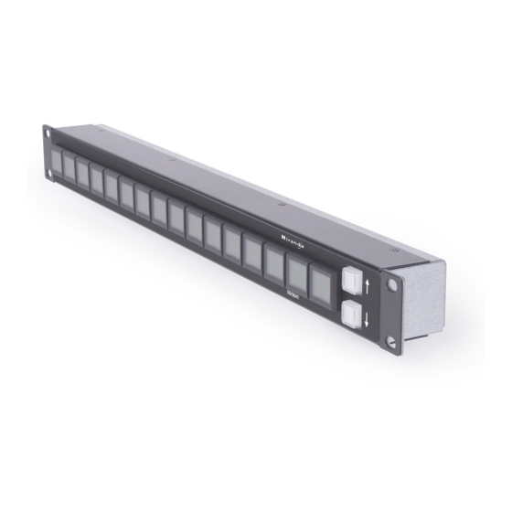
Panel Organization Function Buttons The NV9641 has an array of 16 LCD buttons. Each has 3 lines of text (up to 8 characters per line). The buttons can display one of seven colors dynamically: nominally red, green, blue, purple, amber, yellow, or grey. An eighth color exists — “dark” — when the LCD is off. -
Page 15: Up/Down Buttons
During configuration, you can prescribe NV9641 behavior that depends on the tally inputs. What you connect to the tally interface is, of course, up to you. Miranda provides a breakout cable (WC0053) for the tally connector as a purchase option. -
Page 16: Modes Of Operation
Salvo mode tends to be very brief. • Menu Mode — pressing a Menu button places the NV9641 in “menu” mode. In menu mode, the LCD button array becomes a menu that changes as needed during menu operation. -
Page 17: Other Nv9641 Functions
2. Introduction Other NV9641 Functions Other NV9641 Functions The NV9641 can be configured to perform the following additional functions: • Previous source, free source, and “quick” source. • Lock/protect/release for destinations. • Return to a pre-defined (or default) state. • Hold breakaway levels. - Page 18 2. Introduction Other NV9641 Functions Rev 1.2 • 13 Oct 09...
-
Page 19: Installation
Testing Package Contents If you have ordered one or more NV9641 control panels from Miranda, inspect the shipping con- tainer for damage. If you find any container damage, unpack and inspect the contents. If the con- tents are damaged, notify the carrier immediately. -
Page 20: Installation
NV9000 configuration software. You may use the Panel IP Configuration Utility if you want your NV9641 to have a static IP address or to change it back to DHCP. The panel, as it comes from the factory, defaults to DHCP. -
Page 21: Initialization
ID. Follow these steps for each NV9641 you are installing: 1 Power up the NV9641. Do not connect its Ethernet cable (or disconnect it if it is connected). After a few seconds, the alphanumeric display will show ‘Acquire IP Address’ and show the panel’s current panel ID. -
Page 22: Testing
These are points to consider after you install your NV9641 control panel(s): 1 Do the buttons illuminate? When an NV9641 powers up, its two leftmost LCD buttons are sup- posed to turn green. Does it pass the panel test mentioned above? 2 When the NV9641 powers up and it is connected to the system controller, it should initialize completely. -
Page 23: Configuration
The software with which to configure the NV9641 is NV9000-SE Utilities. Figure 4-1, following, shows the default NV9641 panel configuration page from NV9000-SE Utilities. The Panel IP Configuration Utility is also available if you want the NV9641 to take a static IP address. -
Page 24: Adding A Panel To A Nv9000 Configuration
Adding a Panel to a NV9000 Configuration Adding a Panel to a NV9000 Configuration You must create configurations for the NV9641 using NV9000-SE Utilities. We assume that you are familiar enough with NV9000-SE Utilities that you can understand the following material. It is not difficult material, but some of the concepts might not be familiar to everyone. - Page 25 Adding a Panel to a NV9000 Configuration Choose “NV9641” from the ‘Type’ field. Enter the panel ID you assigned to the panel (during ini- tial power-up) in the ID field. Give a name to the panel in the name field and select a user.
-
Page 26: Nv9641 Panel Configuration Page
Page Table GPIO Definitions Figure 4-1. NV9641 Configuration Page (Default) Similar pages exist for NV9641 suffix templates and for global navigation templates. See Global Navigation on page 41. The items on the page shown in Figure 4-1 apply under the “XY/MD” behavioral model. A some- what different page appears when you choose the “paging”... -
Page 27: Regions Of The Configuration Page
Above the ‘Revert to Saved’ and ‘Save’ buttons (always present) there are 5 main regions: • A graphic representation of the NV9641 panel. On the left are 16 LCD function buttons. Click on a button to assign a function to it. In some cases, you can click or double-click certain buttons to execute the button function. -
Page 28: Configuration Tasks
Commitment Buttons Configuration Tasks The person configuring an NV9641 panel will want to consider how best to use the button page tree under the XY/MD model or the list structure of the button page list under the paging model to sup- port the devices and routers in the router control system at hand. -
Page 29: Panel Options
Normal Release This panel can release “locks” and “protects” set by the designated user (at this panel or any other panel). Force Release This panel can release locks and protects set by any user. NV9641 Control Panel • User’s Guide... - Page 30 4. Configuration Panel Options Default None After a reset, the panel displays no destination device. (This is not Destination recommended.) ‹device› The Panel uses the specified device as the destination after a reset. (The ‘Default State’ button also returns the panel to this destination.) Preset Monitor None The preset source video is not sent to a monitor.
-
Page 31: Checkbox Options
‘Source is Master’ button on the panel. Note: a ‘Source is Master’ button is a toggle that reverses the direction of data routing for devices used in data (control) level takes. NV9641 Control Panel • User’s Guide... - Page 32 A ‘Source/Destination’ button selects a source and a destination. When this box is checked (as it is in the default NV9641 configuration) the button performs an immediate take. When the checkbox is clear, the button sets up the take and the operator must press a ‘Take’ button to complete the take.
-
Page 33: Options Under The Paging Model
Allows the Panel ID to be changed locally at the control panel (in menu mode). • Enable Destination Lock. Check ‘Enable Destination Lock’ so that any ‘Destination Lock’ button on the panel will func- tion. NV9641 Control Panel • User’s Guide... -
Page 34: Button Definitions
A ‘Source/Destination’ button selects a source and a destination. When this box is checked (as it is in the default NV9641 configuration) the button performs an immediate take. When the checkbox is clear, the button sets up the take and the operator must press a ‘Take’ button to complete the take. -
Page 35: Button Specification
4. Configuration Button Definitions The number and names of categories can also change over time and the NV9641 will track those changes too. When a device list appears on the panel, the system lights the ‘up’ button so the operator can easily return to the page containing the category button. -
Page 36: Button Types
4. Configuration Button Definitions Check box “Place this button on all child pages.” When the operator presses a ‘Navigate’ button, its target page appears on the buttons. Any page can have multiple navi- gate buttons and therefore multiple target pages. If you check this option, the but- ton you are defining will occur, in the same position, on all pages in the subtree under the navigation button. - Page 37 In MD mode, the button of a locked destination appears bright red and its button legend is ‘Locked by ‹user›’ and the ‘X-Y Display’ button turns dark red. In X-Y mode, the ‘X-Y Display’ button is low-tally red (not amber) when the preset destination is locked. NV9641 Control Panel • User’s Guide...
- Page 38 Menu This button puts the NV9641 panel in menu mode and displays a menu on the LCD buttons that provides access to a variety of panel options. The button is required if you want the user to have access to the menu.
- Page 39 When this function is enabled (its button is high tally), whatever is on pre- Preset set is retained (on preset) after a take. When the function is disabled (its button is low tally), preset is cleared after a take. NV9641 Control Panel • User’s Guide...
- Page 40 4. Configuration Button Definitions Type Paging Description Selection Selection buttons have many functions, not the least of which is to give feedback (e.g., source and destination mnemonics) when the operator is performing takes. You should configure exactly 8 selection buttons (on any button page) if you want to support level selection in X-Y mode and MD device selection in MD mode.
- Page 41 Switches the panel between X-Y and multi-destination (MD) modes. Mode The configuration page lets you specify a color for this button, but the color you specify is ignored. The button is always green for XY mode and amber for multi-destination mode. NV9641 Control Panel • User’s Guide...
-
Page 42: Edit Navigation Button' Dialog
This option creates a new page in the button tree. During operation, the navigation button you are creating will cause the NV9641 to display, or jump to, that page. The name of the page and the button caption are what you type in the three lines for the button caption. You can change the name of the page in the button page list. -
Page 43: Auto-Fill Options
This options does not create a new page in the button tree. The navigation button you are creat- ing will cause the NV9641 to display the page you select in the associated drop down menu. The button caption is what you type in the three lines for the button caption. -
Page 44: Button Page Table
4. Configuration Button Page Table • Source/Dest Devices This option creates subpages of ‘Source/Destination’ buttons. All use the same destination, which you specify in the ‘Destination Device’ field that becomes enabled for this option. The sources can vary according to the sub-option: •... - Page 45 You might note that if the link field of a page is empty, the page is inaccessible during operation. NV9641 Control Panel • User’s Guide...
-
Page 46: Paging Model
4. Configuration Button Page Table (The exception is the default page which is always available after reset. It might become unavail- able in a configuration that has subpages with no ‘back’ buttons.) Paging Model The page table lists the pages of the button page list. It has 3 columns: ‘Page Number’, ‘Page Name’, and ‘Link to Page Num(s)’. -
Page 47: Tally (Gpio) Window
It has two sections: inputs and outputs. By clicking on one of the input or output buttons, you can configure the input or output. (The NV9641 has no actual tally buttons. It does have a DB25 connector at the rear. The buttons are present in the configuration page to allow you to configure the tally interface.) If you are interested in configuring the tally interface, read Chapter 6, GPIO, on page 63. -
Page 48: Behavior
4. Configuration Selection Buttons mal mode, whichever is in effect at the moment. Normal mode is the default — unless you specify otherwise in the Panel Options. Behavior XY Mode When the panel is in X-Y mode, a set of selection buttons presents a set of virtual levels. The levels displayed correspond to the levels in the level set of a selected destination device. -
Page 49: Md Mode - Hold Mode
Follow these steps to assign virtual levels and MD devices to selection buttons. 1 Decide how many selection buttons you want on the button page. We strongly recommend 8 selection buttons. Create those selection buttons by clicking on the buttons and choosing NV9641 Control Panel • User’s Guide... -
Page 50: Single-Destination Mode
MD destination to the button. 4 Press the down button if, after configuring each selection button, you have additional MD desti- nations to commit to selection buttons. The next set of selection buttons appears on the NV9641 image. -
Page 51: Global Navigation
A suffix template is a single page only. The buttons allowed in a suffix template are a small subset of the buttons supported by NV9641 configurations. Navigate templates support all functions except ‘Global Navigate’. That is because templates cannot be nested. -
Page 52: Referencing A Suffix Template
4. Configuration Global Navigation Referencing a Suffix Template Suffix pages can be accessed through ‘Category’ buttons. When you create a ‘Category’ button, the button type region displays a checkbox option: ‘Use glo- bal suffix page to select devices’: Suffix Suffix checkbox template selection When you check the option, an addition ‘Suffix Page’... -
Page 53: Referencing A Navigate Template
The two buttons labeled ‘ABC’ and ‘DEF’ yield suffixes. When the operator presses a numeral or a suffix, the numeral or suffix is appended to the name of the device being identified. Alphanumeric suffixes are typically single characters. NV9641 Control Panel • User’s Guide... -
Page 54: Template Changes
‘Push changes to panel configs’. When you do, the configuration software adjusts all NV9641 panel configurations to use the modified suffix template. This might override changes you have made to the copy of the suffix page in some panel configuration. -
Page 55: Operation
This chapter is intended specifically for the NV9641 panel operator. Summary As an NV9641 operator, you will be confronted initially with a small panel — 16 buttons of various colors with brief legends and certain color codes. Your NV9641 will be configured according to one of two behavioral models: •... -
Page 56: Modes Of Operation
Single-destination mode is typically an application of ‘Quick Source’ buttons. Secondary modes are: • Setup mode — where the NV9641 is freshly powered up, but disconnected from the network. In this mode, the configurer can preset the NV9641’s panel ID and perform a few diagnostic tasks. -
Page 57: Button Legends
5. Operation Summary • Menu mode — pressing a menu button places the NV9641 in “menu” mode. In menu mode, the LCD button array becomes a menu button panel that changes as needed during menu operation. The menu button is for operators. There is nothing in the menu that concerns operators except LCD brightness. -
Page 58: Level Mapping
5. Operation Summary When a source is preset, prior to a take, the level buttons show the preset source on the middle line of text and the buttons turn yellow: Source CAM4 preset prior to a take. XY-STAT XY-STAT CAM3 CAM3 CAM3 CAM3... -
Page 59: Lists
Operating Concepts Lists The NV9641 can display devices, categories, and salvos in automatically generated lists under the XY/MD model. There are three kinds of lists: • Generated during configuration of a navigation button. These lists are characterized by the pres- ence of “Back”... -
Page 60: Back
You can scroll the pages using back and forward buttons. If you press ‘Back’ while on the first page of the list, the NV9641 returns to the page con- taining the category button. -
Page 61: Chop
However, it is possible for a suffix page to have fewer buttons. When you press a category button, the NV9641 displays the first of perhaps several pages of device buttons. You can scroll the pages using the up and down buttons. If you press ‘Up’ while on the first page of the list, the NV9641 returns to the button page containing the category. -
Page 62: Destination Lock
5. Operation Operating Concepts Destination Lock * This button is a toggle that sets or clears a lock on the current destination. The lock can be removed at the panel that originally set the lock, at a panel that has the same user ID, or by a forced release at any panel. -
Page 63: Free Source
AES1/2 to AES3/4. Follow these steps to create a level mapping: 1 Select a source. 2 Press ‘Level Map’. It goes bright and the XY Display button says “Select Src Level.” Press a level button. NV9641 Control Panel • User’s Guide... -
Page 64: Menu
The default button text is “Level Map” but the button can have any legend. Menu * The button puts the NV9641 panel in menu mode and displays a menu, on the LCD buttons, that provides access to a variety of panel options. -
Page 65: Preset Release
(on preset) after a take. When the function is disabled (its button is low tally), whatever is on preset is discarded after a take. The default button text is “Save Preset” but the button can have any legend. NV9641 Control Panel • User’s Guide... -
Page 66: Selection
5. Operation Operating Concepts Selection Operators use selection buttons to select and unselect levels in X-Y mode and to select and unselect MD destinations in MD mode. A button page that has selection buttons will have up to 8 of them. X-Y Mode When the panel is in X-Y mode, a selection button presents a virtual level that corresponds to the display index for the button and the preset source or destination device. -
Page 67: Source
An undefined button cannot be used and appears dark (unlit) on the panel. X-Y Display * The ‘X-Y Display’ button displays status — in either X-Y mode or MD mode. It also displays other messages in other circumstances, as required. Pressing this button has no effect. NV9641 Control Panel • User’s Guide... -
Page 68: Xy/Md Mode
Release To remove a lock or protect. Some control panels can lock or protect both sources and destinations. However, The NV9641 pro- vides locks and protects for destinations only. A forced release is when the lock or protect is removed by someone other than the owner. A forced release can be performed: •... -
Page 69: Single-Destination Mode
Implicit in the ‘Broadcast’ button is the “source is master” mode. It is not necessary to press ‘Source is Master’ repeatedly. The reason you must press ‘Source is Master’ the first time is that “broadcast mode” is not yet active. NV9641 Control Panel • User’s Guide... -
Page 70: Removing Broadcast Routes
OOOOOO O4 O4 The 3 buttons on the left tell you the current versions of the software in the NV9641. Generally, this is of no relevance unless you are in a diagnostic situation. Press ‘Exit’ on the right to return to the menu. -
Page 71: Lcd Control
77 for a color chart. Setup Mode Setup mode occurs when the NV9641 is disconnected from its network and is freshly powered up. In setup mode, you can set or change the panel ID, determine software versions, and perform a test of the panel’s buttons. - Page 72 5. Operation Setup Mode Press the ‘Menu’ button at the far right to access the setup menu: PANEL PANEL SOFTWARE SOFTWARE PANEL PANEL • • • ID ENTRY ID ENTRY VERSIONS VERSIONS TEST TEST EXIT EXIT MODE MODE There are 3 setup menu choices. The ‘Exit’ button at the far right allows you to leave the menu. •...
-
Page 73: Gpio
The tally interface includes 8 optically isolated inputs and 4 solid-state relay outputs (also optically isolated). Tally devices you connect to inputs can trigger events — through the NV9641 — in the router control system. The router control system can trigger events that — through the relays in the NV9641 —... -
Page 74: Output
Optional Grounding Figure 6-3. GPI Output When a condition (defined for the relay) occurs, the router control system notifies the NV9641 which then opens or closes the relay. The relay switches the customer’s circuit on or off. (It does not power the circuit. Customers must provide their own power.) GPIO Configuration Concepts These are the I/O characteristics of the NV9641’s tally interface:... -
Page 75: Configuring Outputs
Click on a button under ‘Outputs’ to configure one of the 4 tally outputs. Click on a button under ‘Inputs’ to configure one of the 8 tally inputs. There are no actual GPIO buttons on the NV9641 control panel. Configuring Outputs Clicking an output button (one of 4) displays a “Relay Rule”... - Page 76 The actual logic takes place in the router control system, based on the state of the NV9641 inputs and other system-wide events. The router control system sends signals to the NV9641 instructing it to open or close its relays.
-
Page 77: Configuring Inputs
An event is signalled when a transition occurs on the input from on to off or from off to on. You can configure the NV9641 to recognize either occurrence on any of the 8 inputs, and specify one of 4 behaviors for each event or both: 1 Execute a salvo. - Page 78 Its 8 inputs can be switched on or off by your external devices. When an input transitions on or off, the NV9641 can respond with one of 4 actions, such as executing a salvo. (It is the system that actu- ally executes the salvo.)
-
Page 79: Technical Details
7. Technical Details Chapter 7 provides electrical and mechanical specifications for the NV9641. It discusses these top- ics: • Power Specifications • NV9641 Specifications • Environmental Specifications • Defaults • Drawings Power Specifications Table 7-1 provides power specifications for the NV9641 control panels. -
Page 80: Nv9641 Specifications
DC Output Figure 7-1. The power output has Molex 4-pin plug. See Power Cord Retention on page 78. NV9641 Specifications Table 7-3 provides specifications for the NV9641. Table 7-3. NV9641 Physical Specifications Specification Detail Dimensions Height: 1.72″ (43.7mm), fits EIA 1 RU (1.75″ or 44.5mm), Width: 19.0″... -
Page 81: Environmental Specifications
Buttons: high-tally is maximum brightness; low-tally is low brightness. Configuration Page The initial configuration page for a new NV9641 configuration provides 8 selection buttons (rec- ommended), an XY/MD mode selection button, an X-Y Display button, and a take button. The default panel options are: Panel mode: Multi-destination. -
Page 82: Drawings
7. Technical Details Drawings Drawings The drawings on the following pages identify features and provide overall and critical dimensions. Rev 1.2 • 13 Oct 09... - Page 83 7. Technical Details Drawings Figure 7-2. Front and Top Views of the NV9641 NV9641 Control Panel • User’s Guide...
- Page 84 7. Technical Details Drawings Figure 7-3. Rear and Top Views of the NV9641 Rev 1.2 • 13 Oct 09...
-
Page 85: Misc. Topics
8 of the time code router. GPIO General Purpose Input and Output. A generic term for the NV9641’s tally interface. The tally inter- face is called the “GPI Interface” at the rear of the NV9641. - Page 86 8. Misc. Topics Glossary The system administrator may create a single “super user” personal identification number (PIN) that functions as a passcode. A PIN is 4–6 digits in length. The PIN allows certain operators to per- form functions such as (1) forced release on a control panel that is configured for normal release or (2) changing the ID of a control panel.
-
Page 87: Lcd Buttons
To apply a label to a button, pull the clear plastic cap from the button, insert the label in the cap, and replace the cap. The caps come off easily. No tools are required. We recommend that you not use adhesive. NV9641 Control Panel • User’s Guide... -
Page 88: Power Cord Retention
8. Misc. Topics Power Cord Retention Power Cord Retention Use the supplied retention strap to keep the AC power cord firmly connected to the power supply. Follow these steps to use the strap: 1 Firmly insert the AC power cord into the power supply. Examine the last figure in this section to see how the strap should be applied. -
Page 89: Ordering Information
12V power supply, 4-pin Molex connector, with cord, and cord retention strap. NV9641 NV9000 control panel. 16 button, 1RU, XY/MD/paging, hierarchical. WC0053 Optional breakout cable for the tally interface SB0033 Software and documentation CD. NV9641 Control Panel • User’s Guide... - Page 90 8. Misc. Topics Ordering Information Rev 1.2 • 13 Oct 09...
-
Page 91: Index
Broadcast (button) ....26, 50, 59 Button captions ... . 25, 32, 47, 50–51, 57 NV9641 Control Panel • User’s Guide... - Page 92 Button pages ....4, 32, 45, 49, 53–54 NV9641 ......13 deletion .
- Page 93 GPIO ..... . . 10, 13, 17, 63, 71 NV9641 ......69–70 connector .
- Page 94 ....9 Installation, NV9641 ......9 Mailing address .
- Page 95 ......iii NV9641 ..... . . 2, 9–10, 13, 79 technical support .
- Page 96 Power specifications NV9641 ......69 Sales number ......iii power supply .
- Page 97 Terms, conventions and abbreviations ..2 NV9641 ......69–70 Testing your installation .
- Page 98 WC0053 ......5, 10, 79 Website, Miranda ......iii Velcro strap .
Need help?
Do you have a question about the NV9641 and is the answer not in the manual?
Questions and answers