
Subscribe to Our Youtube Channel
Related Manuals for Miranda NV9607


Summary of Contents for Miranda NV9607
- Page 1 NV9607 Control Panel User’s Guide Miranda Technologies Inc. 3499 Douglas B. Floreani Montreal, Quebec Canada H4S 2C6...
- Page 2 The information and intellectual property contained herein is confidential between Miranda and the client and remains the exclusive property of Miranda. If you find any problems in the documentation, please report them to us in writing. Miranda does not warrant that this document is error-free.
- Page 3 Contact Miranda for details on the software license agreement and product warranty. Technical Support Contact Information Miranda has made every effort to ensure that the equipment you receive is in perfect working order and that the equipment fits your needs. In the event that problems arise that you cannot resolve, or...
- Page 4 D. Cox Restriction on Hazardous Substances (RoHS) Miranda is in compliance with EU Directive RoHS 2002/95/EC governing the restricted use of cer- tain hazardous substances and materials in products and in our manufacturing processes. Miranda has a substantial program in place for RoHS compliance that includes significant invest- ment in our manufacturing process, and a migration of Miranda product electronic components and structural materials to RoHS compliance.
- Page 5 The fuse symbol indicates that the fuse referenced in the text must be replaced with one having the ratings indicated. The presence of this symbol in or on Miranda equipment means that it has been designed, tested and certified as complying with applicable Underwriter’s Laboratory (USA) regulations and rec- ommendations.
- Page 6 General Warnings A warning indicates a possible hazard to personnel which may cause injury or death. Observe the following general warnings when using or working on this equipment: • Heed all warnings on the unit and in the operating instructions. •...
-
Page 7: Table Of Contents
NV9607 Panel Configuration Page ........ - Page 8 Table of Contents Chapter 5 Operation ............. . . 31 Summary .
- Page 9 The GPIO Section of the NV9607 Page ........
- Page 10 Table of Contents Rev 1.0 • 21 May 10...
-
Page 11: Preface
1. Preface Chapter 1 is an introduction to the NV9607 User’s Guide. It presents the following topics: • Chapter Structure • The PDF Document • Terms, Conventions and Abbreviations Chapter Structure The following chapters provide detailed information regarding the NV9607 Control Panel: •... -
Page 12: Terms, Conventions And Abbreviations
• Press the SRC 12 button ... The following terms and abbreviations are used throughout this guide: • The term “control panel” refers to the NV9607 control panel and to NV96xx control panels, in general. • “High tally” means that a button is brightly illuminated. High-tally usually means that the but- ton function is selected or active. -
Page 13: Introduction
(if present) represent one of two sets of destinations. An operator can toggle between the two sets. The sets of functions differ in the different operating modes. 1 An equivalent NV9607V — a GUI that is called a “virtual panel”— is available. It emulates the NV9607. NV9607 Control Panel • User’s Guide... -
Page 14: Panel Organization
Function Buttons The NV9607 has 4 rows of function buttons. The upper two rows have 24 buttons. The lower two rows have 34 buttons. The total is 116 function buttons. The set of buttons differ in each of the 4 operating modes. -
Page 15: Alphanumeric Display
AUDIO 2 Single-destination mode Single-destination mode with breakaway The main difference between XY mode, SD mode, and SD mode with breakaway is the title in the first line: ‘X - Y’, ‘Single’, and ‘1Dst/wBrk’ respectively. NV9607 Control Panel • User’s Guide... - Page 16 HD and ‘TimeCode’ are not defined for VTR 1. • Level/Dest. In MD mode, the ‘Level/Dest’ column presents all the MD destinations defined in the NV9607 configuration. (Actual destinations are defined in the NV9000 configuration.) Operators might need to scroll to see or select a destination.
-
Page 17: Flags
During configuration, you can prescribe NV9607 behavior that depends on the tally inputs. What you connect to the tally interface is, of course, up to you. Miranda provides a breakout cable (WC0053) that can be used with the tally connector, as a purchase option. -
Page 18: Modes Of Operation
The panel’s set of button functions varies with the mode. The modes (or behavioral models) are determined at configuration. The operator cannot switch between different modes. The NV9606 control panel can operate as an extension of the NV9607. See the NV9606 User’s Guide for details. Limited X-Y Mode In limited X-Y mode, takes occur from a single source to a single destination (selectable). -
Page 19: Multi-Destination Mode
NV9607’s panel ID and perform a few diagnostic tasks. • Menu mode — pressing a menu button places the NV9607 in “menu” mode. In menu mode, the buttons lose their normal functions and become part of a menu that changes as needed during menu operation. - Page 20 2. Introduction Other NV9607 Functions Rev 1.0 • 21 May 10...
-
Page 21: Installation
Testing Package Contents If you have ordered one or more NV9607 control panels from Miranda, inspect the shipping con- tainer for damage. If you find any container damage, unpack and inspect the contents. If the con- tents are damaged, notify the carrier immediately. -
Page 22: Installation
NV9000 configuration software. You may use the Panel IP Configuration Utility if you want to your NV9607 to have a static IP address (with respect to the NV9000) or to use DHCP. The panel, as it comes from the factory, defaults to DHCP. -
Page 23: Initialization
(All panel IDs must be unique.) You can now prepare an NV9607 configuration in NV9000-SE Utilities and upload the configura- tion to the NV9607. You need the panel ID to create a NV9607 configuration. When you upload the NV9607 Control Panel • User’s Guide... -
Page 24: Testing
These are points to consider after you install your NV9607 control panel(s): 1 Do the buttons illuminate? When an NV9607 powers up, one or more of its buttons are sup- posed to turn green or amber. Did it pass the panel test mentioned above? 2 When the NV9607 powers up and it is connected to the system controller, it should initialize completely. -
Page 25: Configuration
This chapter addresses configurers. Operators and other persons not interested in NV9607 configu- ration need not read this chapter. Summary The NV9607 is a relatively simple panel. It has 116 function buttons and a small display. Although it has relatively few button functions, there are 4 operating modes. •... - Page 26 Click ‘Add Control Panel’ at the bottom of the configuration page. The ‘Add Control Panel’ page appears: Choose “NV9607” from the ‘Type’ field. In the ID field, enter the panel ID you assigned to the panel while it was in setup mode. (You can change the panel ID in NV9000-SE Utilities.) Give a name to the panel in the name field and select a user.
- Page 27 There are 2 other buttons, ‘Suffix’ and ‘Navigate’, both dim (disabled). These do not apply to the NV9607. Return to the ‘Control Panels’ page to view your new entry. To edit an NV9607 configuration, dou- ble-click its list entry: You will then see the panel configuration page for the selected NV9607.
-
Page 28: Nv9607 Panel Configuration Page
4. Configuration NV9607 Panel Configuration Page NV9607 Panel Configuration Page This is the default NV9607 panel configuration page in NV9000-SE Utilities: Panel Image Button Definition Section GPIO Section Panel Options Display Options Figure 4-1. NV9607 Configuration Page (Default) After you configure buttons, the appearance of the panel buttons will have changed. The panel but- tons on this page will show legends, determined from the button type assigned to the button. -
Page 29: Configuration Tasks
Configuration Tasks The person configuring an NV9607 panel will want to consider how best to use the buttons to sup- port the devices and routers in the router control system at hand. Trade-offs must be made. -
Page 30: Panel Options
4. Configuration Panel Options Panel Options The panel options section, at the right of the configuration page, has two parts: drop-down menus and checkbox options. These are the drop-down menus: These are its drop-down menu options: Panel Behavioral Limited X-Y In limited X-Y mode, takes occur from a single source to a single Model destination (which is selectable). -
Page 31: Checkbox Options
When this checkbox is checked, the panel powers up in “hold mode.” Otherwise it powers up with hold mode off. Hold mode, under single-destination mode with breakaway, causes the selected levels to be retained after a take. If hold mode is off, all levels become selected after a take. NV9607 Control Panel • User’s Guide... -
Page 32: Button Definitions
Button Specification The button definition section configures the button you have selected in the image of the NV9607: When you choose a button type, additional drop-down menus can appear, depending on the button type, allowing you to further specify the button’s behavior. -
Page 33: Button Types
The lock can be removed only by the user that originally set the lock, or by a panel that has “Force Release” enabled. The button definition has no fields to configure. The NV9607 provides no explicit indication, during operation, whether a destination is locked or unlocked. NV9607 Control Panel • User’s Guide... - Page 34 — even the user who issued the lock — from routing to the destination. The button definition has no fields to configure. The NV9607 provides no explicit indication, during operation, whether a destination is locked or unlocked. Destination The button toggles between the first and second destination sets.
- Page 35 Menu This button puts the NV9607 panel in menu mode and displays a menu on the buttons that provides access to a variety of panel functions. With- out the button, the operator has no access to the menu functions.
- Page 36 4. Configuration Button Definitions Type Modes Description Panel Lock The button prevents accidental changes to the panel settings, especially router crosspoints. When the panel is locked, the button array becomes blank except for the Panel Lock button which becomes high tally red. Pressing the panel lock button again reverts the panel to its previous state.
- Page 37 At the limit, you could configure up to 116 desti- nations. (When the NV9607 has an NV9606 extension, you could configure up to 68 additional destinations.) The destination assigned to the button does not change when the source page changes.
- Page 38 4. Configuration Button Definitions Type Modes Description Source/ The button selects both a source and a destination and performs an Destination immediate take. Source/dest buttons are not subject to source preview mode. In fact they become inactive in source preview mode. Source/dest buttons are not subject to source shift or destination shift.
-
Page 39: Multi-Destination Configuration
‘Take’ button is required to complete the take. Potentially, all 116 buttons of a NV9607 could be source buttons, each having a unique destination. Thus, at that extreme, a panel in multi-destination mode could represent 116 destinations and give operators the choice of two sources for each destination. - Page 40 4. Configuration Multi-Destination Configuration Rev 1.0 • 21 May 10...
-
Page 41: Operation
This chapter is intended specifically for the NV9607 panel operator. Summary As an NV9607 operator, you will be confronted initially with a relatively simple panel — 116 but- tons and a small display. The panel’s buttons can have arbitrary legends. Some buttons can be applied differently in other modes (such as menu mode). -
Page 42: Single-Destination Mode
5. Operation Summary Generally, to operate the panel, you choose a destination, (possibly) choose desired breakaway lev- els, and choose a source. Choosing a source for a destination completes the take unless source pre- view mode is active. In that case, pressing a ‘Take’ button is required for the completion of the take. This paradigm has slight variations in the different modes. -
Page 43: Secondary Modes
Because the buttons of the NV9607 are small, it is not easy to create legend inserts. There is room above the buttons for cus- tomers to place adhesive-backed legends. -
Page 44: Operating Concepts
5. Operation Operating Concepts Operating Concepts Source Shift Source shift applies in all modes. Each source button can represent two sources. A ‘Source Shift’ button selects which of the two sources the source button will select. (The concept is similar to the shift key or the ‘caps lock’ key on a keyboard.) A source shift button is a toggle that enables either the first or second source of source buttons. -
Page 45: Hold
‘Preview’ column of the display and a take button (if your panel has one) turns red. It is necessary to press the take button to complete the take. After the take, the take button goes dark once again. NV9607 Control Panel • User’s Guide... -
Page 46: Buttons
After you turn it on, source preview mode remains in effect until you turn it off. Buttons The NV9607 has 3 classes of button functions: • Dedicated functions, such as ‘Default State’ and ‘Chop’. • Variable functions, such as ‘Salvo’, ‘Source’, or ‘Destination’. A salvo button executes a spe- cific system salvo. -
Page 47: Default State
If you attempt to take a source to a destination that is locked (or protected by another user), the message “Some levels did not switch” appears in the display. Locks apply to selected levels in single-destination mode with breakaway. The NV9607 provides no explicit indication, during operation, whether a destination is locked or unlocked. S, B, X Destination Protect This button is a toggle that sets or clears a protect on the current destination device. -
Page 48: Destination Shift
5. Operation Operating Concepts The NV9607 provides no explicit indication, during operation, whether a destination is locked or unlocked. Destination Shift The ‘Destination Shift’ button toggles between the first and second destination sets (which are available only in limited X-Y mode). -
Page 49: Name Set Toggle
The button does not restore the previous destination. If you changed the destination and press ‘Pre- vious Source’, the take will not restore the previous route. Salvo The salvo button executes a system salvo immediately. NV9607 Control Panel • User’s Guide... -
Page 50: Source
5. Operation Operating Concepts Source The button selects a source. The source name appears in the ‘Status’ display. Pressing a source button completes a take unless the panel is in source preview mode. In source preview mode, pressing a ‘Take’ button is required for the completion of a take. The nature of source buttons differs according to the panel’s configured operating mode: •... -
Page 51: Source/Destination
No one but the owner can route to the destination. Release To remove a lock or protect. Some control panels can lock or protect both sources and destinations. However, The NV9607 pro- vides locks and protects for destinations only. NV9607 Control Panel • User’s Guide... -
Page 52: Locks And Protects With Breakaway
5. Operation Operating Concepts A forced release is when the lock or protect is removed by someone other than the owner. A forced release can be performed: • At any panel configured with release mode set to “forced release.” • At any other panel with “force release” enabled. The ‘Destination Lock’... -
Page 53: Case 2 - Single-Destination Mode, Breakaway
The ‘Preview’ field of the display shows the source you chose and the take button turns red. If that is the correct source, press a ‘Take’ button. If it is not the correct source, you can press another source and then press a ‘Take’ button. NV9607 Control Panel • User’s Guide... -
Page 54: Case 4 - Multi-Destination Mode
There are no destination buttons. Potentially, all 116 buttons of a NV9607 could be source buttons, each having a unique destination. Thus, at that extreme, a panel in multi-destination mode could represent 116 destinations and give operators the choice of two sources for each destination. -
Page 55: Name Sets
1 Ensure that all devices that you want to include in the route are not locked or protected — and that their machine control levels can be acquired. 2 Ensure that the panel has a ‘Broadcast’ button. If it does not, broadcast routes are not possible. Consult your administrator. NV9607 Control Panel • User’s Guide... -
Page 56: Performing A Broadcast Take
5. Operation Operating Concepts 3 Ensure that your data router has been configured as “data forward.” In this mode, the router expects the source (e.g., playback device) to control the destination (e.g., recording device). 4 Cue your playback device. (After the take, you must manually start the playback.) Performing a Broadcast Take Follow these steps: 1 Select a destination and route a source to it. -
Page 57: Semi-Automatic Data Routing
Case 1 — Single-Destination Mode, with or without Breakaway Follow these steps: 1 Verify that the default destination appears in the ‘Destination’ field of the display. 2 Select a source. This is the first source. NV9607 Control Panel • User’s Guide... -
Page 58: Case 2 - Limited X-Y Mode
5. Operation Operating Concepts 3 Press the chop button. 4 Select another source. This is the second source. The chop is immediately activated on the rout- ers (of the default destination) that support chop. To terminate the chop, (1) press the chop button again to turn it off, then (2) select any source. Case 2 —... -
Page 59: Menu Mode
Menu Mode Menu Mode The NV9607 enters menu mode if it has a menu button and you press the menu button. The menu uses some of the buttons on your panel. The legends and functions of these buttons in normal operating mode do not apply while the panel is in menu mode. -
Page 60: Software Submenu
5. Operation Menu Mode Software Submenu The software submenu appears when you press button 1 under the main menu: BOOT: SV0639-060000 Server: SV0921-66 Main Menu Exit The software menu is for viewing only. Press button 23 to return to the main menu or button 24 to exit menu mode: Main Menu Software... -
Page 61: Panel Submenu
Note that the numeric keys range from 0 (at the left) to 9. Press button 20 to cancel the new panel ID; press button 21 to save it. Press button 23 to return to the panel menu or button 24 to exit menu mode. NV9607 Control Panel • User’s Guide... -
Page 62: Illumination Submenu
5. Operation Menu Mode Illumination Submenu The illumination submenu appears when you press button 2 under the panel menu: Illumination Menu Lo Value Hi Value 100% Illumination Lo Panel Menu Illumination Hi Exit These are the buttons involved: Illumination Menu Lo Value Hi Value 100%... -
Page 63: Setup Mode
Setup Mode Setup Mode Setup mode occurs when the NV9607 is disconnected from its network and is freshly powered up. In setup mode, you can set or change the panel ID, identify the software version, and perform a test of the panel’s buttons. It is in setup mode that you must initially set the panel ID. - Page 64 5. Operation Setup Mode If you do not want to change the panel ID, just press the setup button again, without entering a panel ID. Following the panel ID is the display of the software version: APPLICATION S/W: SV0639-06 A0 FIRMWARE VERSION: This is a view-only menu;...
- Page 65 Pressing the setup button (i.e., button 25) will terminate the button test and return you to the initial display of setup mode. At this point — if you have a assigned your NV9607 a suitable panel ID — you may connect your NV9607 to the panel network of your NV9000 system.
- Page 66 5. Operation Setup Mode Rev 1.0 • 25 May 10...
-
Page 67: Gpio
The tally interface includes 8 optically isolated inputs and 4 solid-state relay outputs (also optically isolated). Tally devices you connect to inputs can trigger events — through the NV9607 — in the router control system. The router control system can trigger events that — through the relays in the NV9607 —... -
Page 68: Output
Optional Grounding Figure 6-3. GPI Output When a condition (defined for the relay) occurs, the router control system notifies the NV9607 which then opens or closes the relay. The relay switches the customer’s circuit on or off. (It does not power the circuit. Customers must provide their own power.) GPIO Configuration Concepts These are the I/O characteristics of the NV9607’s tally interface:... -
Page 69: Configuring Outputs
Click on a button under ‘Outputs’ to configure one of the 4 tally outputs. Click on a button under ‘Inputs’ to configure one of the 8 tally inputs. There are no actual GPIO buttons on the NV9607 control panel. Configuring Outputs Clicking an output button (one of 4) displays a “Relay Rule”... - Page 70 The actual logic takes place in the router control system, based on the state of the NV9607 inputs and other system-wide events. The router control system sends signals to the NV9607 instructing it to open or close its relays.
-
Page 71: Configuring Inputs
Its 8 inputs can be switched on or off by your external devices. When an input transitions on or off, the NV9607 can respond with one of 4 actions, such as executing a salvo. (It is the system that actu- ally executes the salvo.) - Page 72 6. GPIO Configuring Inputs Rev 1.1 • 21 May 10...
-
Page 73: Technical Details
7. Technical Details Chapter 7 provides electrical and mechanical specifications for the NV9607. It discusses these top- ics: • Power Specifications • NV9607 Specifications • Environmental Specifications • Defaults • Drawings Power Specifications Table 7-1 provides power specifications for the NV9607 control panels. -
Page 74: Nv9607 Specifications
DC Output Figure 7-1. The power output has Molex 4-pin plug. See Power Cord Retention on page 71. NV9607 Specifications Table 7-3 provides specifications for the NV9607. Table 7-3. NV9607 Physical Specifications Specification Detail Dimensions Height: 1.72″ (43.7.9 mm), fits EIA 1 RU (1.75″ or 44.5 mm), Width: 19.0″... -
Page 75: Environmental Specifications
7. Technical Details Environmental Specifications Environmental Specifications Table 7-4 provides environmental specifications for the NV9607. Table 7-4. NV9607 Environmental Specifications Specification Detail Operating temperature 0–30°C, ambient. Relative humidity 0 to 90%, non-condensing. Cooling No fan required. NV9607 Control Panel • User’s Guide... -
Page 76: Defaults
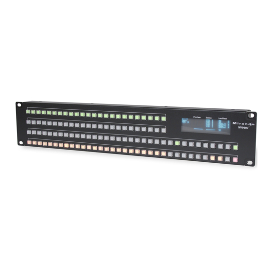
Initial Panel State Destination: the configured default. Buttons: low-tally is 40% brightness by default and stays at its most recent setting. Configuration Page The initial NV9607 configuration has no buttons defined. The default panel options are: Behavioral model: Single-destination. Release mode: Normal. - Page 77 7. Technical Details Drawings Figure 7-2. Front View of the NV9607 NV9607 Control Panel • User’s Guide...
- Page 78 7. Technical Details Drawings Figure 7-3. Top, and Rear Views of the NV9607 Rev 1.0 • 21 May 10...
-
Page 79: Misc. Topics
8 of the time code router. GPIO General Purpose Input and Output. A generic term for the NV9607’s tally interface. The tally inter- face is called the “GPI Interface” at the rear of the NV9607. - Page 80 8. Misc. Topics Glossary form functions such as (1) forced release on a control panel that is configured for normal release or (2) changing the ID of a control panel. Port A port is the physical connection on a router. A port can only be an input port or an output port. Salvo A salvo is a stored group of commands that can be recalled and executed at a NV9000 control panel.
-
Page 81: Power Cord Retention
6 Examine the strap though its path around the cord and power supply. Be sure that no slack exists and that it is tight the full length of the strap. If necessary, adjust and cinch it more tightly. NV9607 Control Panel • User’s Guide... - Page 82 8. Misc. Topics Power Cord Retention Rev 1.0 • 21 May 10...
-
Page 83: Index
..... . .38 destination protect ....24, 37, 42 NV9607 Control Panel • User’s Guide... - Page 84 Destination field ......44 NV9607 ......15 Destination lock (button) .
- Page 85 Electrical specifications NV9607 ......63–64 power supply ......63 Electrostatic discharge .
- Page 86 Keycaps ........4 Miranda email, tech support ..... .iii mailing address .
- Page 87 ......21 NV9607 ......63 configuration .
- Page 88 RJ-45 connector ......12 NV9607 ......63–64 RMA .
- Page 89 WC0053 ....... . . 7 Website, Miranda ......iii Weight .
- Page 90 Index Rev 1.0 • 18 Aug 10...
Need help?
Do you have a question about the NV9607 and is the answer not in the manual?
Questions and answers