Cisco Catalyst 8500 Series Hardware Installation Manual
Edge platforms
Hide thumbs
Also See for Catalyst 8500 Series:
- Hardware installation manual (100 pages) ,
- Regulatory compliance and safety information manual (31 pages) ,
- Manual (18 pages)
Table of Contents
Advertisement
Advertisement
Table of Contents

Related Manuals for Cisco Catalyst 8500 Series


Summary of Contents for Cisco Catalyst 8500 Series
- Page 1 Cisco Catalyst 8500 Series Edge Platforms Hardware Installation Guide First Published: 2020-10-30 Americas Headquarters Cisco Systems, Inc. 170 West Tasman Drive San Jose, CA 95134-1706 http://www.cisco.com Tel: 408 526-4000 800 553-NETS (6387) Fax: 408 527-0883...
- Page 2 Cisco has more than 200 offices worldwide. Addresses and phone numbers are listed on the Cisco website at www.cisco.com/go/offices. Cisco and the Cisco logo are trademarks or registered trademarks of Cisco and/or its affiliates in the U.S. and other countries. To view a list of Cisco trademarks, go to this URL: www.cisco.com...
-
Page 3: Table Of Contents
C H A P T E R 2 Preparing Your Site for Installation Prerequisites and Preparation Site Planning Checklist Safety Guidelines Safety Warnings Safety Recommendations Cautions and Regulatory Compliance Statements for NEBS Cisco Catalyst 8500 Series Edge Platforms Hardware Installation Guide... - Page 4 Attaching the Rear Rack-Mount Brackets Mounting the Router in the Rack Two-Post Rack Installation Four-Post Rack Installation Attaching the Cable Management Bracket Chassis Ground Connection Recommended Tools and Supplies Attaching a Chassis Ground Connection Cisco Catalyst 8500 Series Edge Platforms Hardware Installation Guide...
- Page 5 Wiring the DC Input Power Source Removing and Replacing Micro-USB Removing and Replacing a DIMM Removing a DIMM Replacing a DIMM Removing and Replacing Fans Removing the Fans Repacking the Router Cisco Catalyst 8500 Series Edge Platforms Hardware Installation Guide...
- Page 6 Contents Cisco Catalyst 8500 Series Edge Platforms Hardware Installation Guide...
-
Page 7: Preface
Document Revision History The following table records the changes made to this document. Document Objectives This publication describes the installation of the Cisco Catalyst 8500 Series Edge Platforms and replacement or upgrade of field-replaceable units (FRUs). Audience This publication is primarily designed for persons responsible for installing, maintaining, and troubleshooting the Cisco Catalyst 8500 Series Edge Platforms. -
Page 8: Conventions
Timesaver. Caution Means reader be careful. In this situation, you might perform an action that could result in equipment damage or loss of data. Cisco Catalyst 8500 Series Edge Platforms Hardware Installation Guide viii... -
Page 9: Obtaining Documentation And Submitting A Service Request
Documentation, which also lists all new and revised Cisco technical documentation. Subscribe to the What's New in Cisco Product Documentation as a Really Simple Syndication (RSS) feed and set content to be delivered directly to your desktop using a reader application. The RSS feeds are a free service and Cisco currently supports RSS version 2.0. - Page 10 Preface Obtaining Documentation and Submitting a Service Request Cisco Catalyst 8500 Series Edge Platforms Hardware Installation Guide...
-
Page 11: Overview
C H A P T E R Overview The Cisco Catalyst 8500 Series Edge Platforms are well suited for medium-sized and large enterprise branch offices for high WAN IPSec performance with integrated SD-WAN services. The Cisco Catalyst 8500 Series Edge Platforms target these use cases: •... -
Page 12: Hardware Features
Overview Hardware Features Hardware Features Table 1: Hardware Feature for Cisco 8500 Series Catalyst Edge Platforms Feature C8500-12X4QC C8500-12X Rack Units Support for a 480 GB SSD hard Support for a 480 GB SSD hard drive drive RJ-45 RJ-45 console port... - Page 13 Red - System Failure link, On Link is up. Yellow - System booted S - Speed LED - One to Rommon blink 10Mbps, Two blinks Green - System Booted to 100Mbps, Three blinks 1000Mbps Cisco Catalyst 8500 Series Edge Platforms Hardware Installation Guide...
-
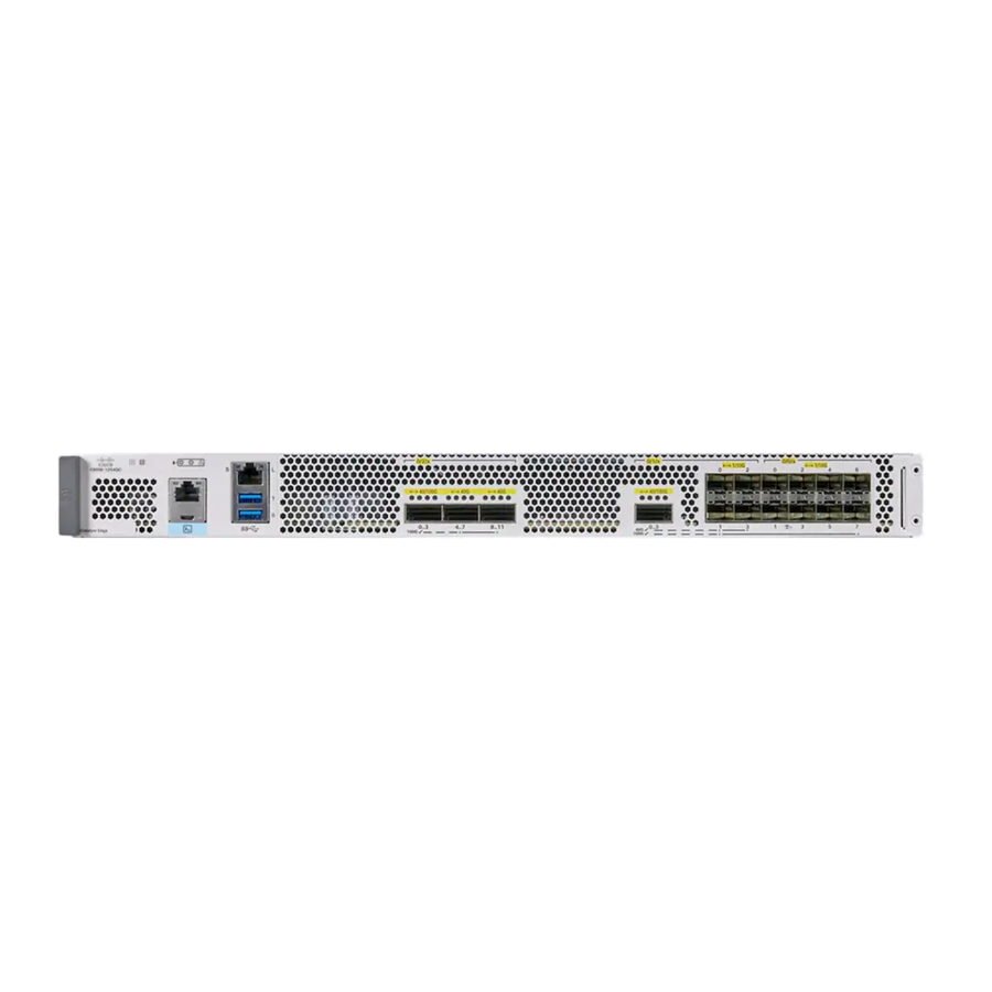
Page 14: Front And Rear View Of Cisco C8500-12X
Console USB LEDs Bay 0 - 12x 1/10GE SFP+ Console RJ-45 ports The following figure shows the rear view of of Cisco C8500-12X Figure 2: Cisco C8500-12X Rear View Fans Power Switch Power supply input LED Power supply failure LED... -
Page 15: Bay Configuration - C8500-12X4Qc
Bay 0 – 8xSFP+ : Configurable as - 8x Configurable as: 1x 100G 10/1G or 1x 40G or 4x 10/1G Bay Configuration - C8500-12X4 The C8500-12X4 has one bay with twelve confgurable Cisco Catalyst 8500 Series Edge Platforms Hardware Installation Guide... -
Page 16: Ac Power Supply
Console Bay 0 – 12XSFP+: Label Tray Configurable as: 12X10/1G AC Power Supply Figure 3: AC Power Supply Used in the Cisco C8500-12X4QC Router FAIL and OK LEDs AC power connector Handle Retaining latch DC Power Supply The DC (PWR-CH1-950WDCR) input connector is a two-wire connector with connection polarity from left to right (when facing the unit) of positive (+) negative (–). -
Page 17: Power Supply Leds
Power Supply Condition Green (OK) LED Status Amber (FAIL) LED Status No AC power to all power supplies Power Supply Failure (includes over voltage, over current, over temperature and fan failure) Cisco Catalyst 8500 Series Edge Platforms Hardware Installation Guide... -
Page 18: Power Supply Fans
Standby position. Serial Number and PID/VID Label Location The following figure show the location of the serial number and the PID/VID label on the Cisco Catalyst 8500 Series Edge Platforms. Figure 5: Cisco Catalyst 8500 Series Edge Platforms Serial Number and PID/VID Label Location... -
Page 19: Preparing Your Site For Installation
C H A P T E R Preparing Your Site for Installation This chapter contains important safety information you should know before working with working with the Cisco Catalyst 8500 Series Edge Platforms and guides you through the process of preparingyour site for router installation. •... -
Page 20: Site Planning Checklist
• Router should always be transported or stored in its shipping package in the upright position. • Keep the router in the shipping container until you have determined the installation site. Note Inspect all items for shipping damage. If an item appears damaged, contact a Cisco customer service representative immediately. Site Planning Checklist Use the following checklist to perform and account for all the site-planning tasks described in this chapter: •... -
Page 21: Safety Recommendations
Safety Recommendations The following guidelines will help to ensure your own safety and protect your Cisco equipment. This list does not cover all potentially hazardous situations, so be alert. • Cisco safety policy mandates that all its routers must conform to the requirements of IEC 60950, with appropriate national deviations, as a minimum. -
Page 22: Standard Warning Statements
Use the statement number provided at the end of each warning to locate its translation in the translated safety warnings that accompanied this device. SAVE THESE INSTRUCTIONS Cisco Catalyst 8500 Series Edge Platforms Hardware Installation Guide... -
Page 23: General Safety Warnings
Warning This unit is intended for installation in restricted access areas. A restricted access area can be accessed by skilled, instructed or qualified personnel. Cisco Catalyst 8500 Series Edge Platforms Hardware Installation Guide... - Page 24 Viewing the laser output with certain optical instruments (for example, eye loupes, magnifiers, and microscopes) within a distance of 100 mm may pose an eye hazard. Cisco Catalyst 8500 Series Edge Platforms Hardware Installation Guide...
-
Page 25: Site Planning
Do not operate the system unless all cards, faceplates, front covers, and rear covers are in place. Site Planning This section contains site-planning information, and will help you plan for the installation of the Cisco Cisco Catalyst 8500 Series Edge Platforms. General Precautions... -
Page 26: Site Cabling Guidelines
This section contains guidelines for wiring and cabling at your site. When preparing your site for network connections to the Cisco Catalyst 8500 Series Edge Platforms, consider the type of cable required for each component, and the cable limitations. Consider the distance limitations for signaling, EMI, and connector compatibility. -
Page 27: Interference Considerations
Strong EMI can destroy the signal drivers and receivers in the Cisco Catalyst 8500 Series Edge Platforms and even create an electrical hazard by causing power surges through power lines into installed equipment. These problems are rare, but could be catastrophic. -
Page 28: Rack-Mounting Guidelines
Lightning and AC Power Fault Interference If signal wires exceed recommended cabling distances, or if signal wires pass between buildings, you should consider the effect that a lightning strike in your vicinity might have on the Cisco Catalyst 8500 Series Edge Platforms. -
Page 29: General Rack-Selection Guidelines
• Do not step or stand on any component or system when servicing other systems or components in a rack. • When mounting the Cisco Catalyst 8500 Series Edge Platforms in a partially filled rack, load the rack from the bottom to the top with the heaviest component at the bottom of the rack. -
Page 30: Equipment Rack Guidelines
Locating for Safety If the Cisco Catalyst 8500 Series Edge Platforms is the heaviest or the only piece of equipment in the rack, consider installing it at or near the bottom to ensure that the rack’s center of gravity is as low as possible. -
Page 31: Preventing Electrostatic Discharge Damage
• Before beginning any procedures requiring access to the chassis interior, locate the emergency power-off switch for the room in which you are working. • Disconnect all power and external cables before installing or removing a chassis. Cisco Catalyst 8500 Series Edge Platforms Hardware Installation Guide... -
Page 32: Chassis-Lifting Guidelines
The following tools and equipment are recommended as the minimum necessary equipment to install the Cisco Catalyst 8500 Series Edge Platforms. You may need additional tools and equipment to install associated equipment and cables. You may also require test equipment to check electronic and optical signal levels, power levels, and communications links. -
Page 33: Unpacking And Verifying Shipping Contents
Checking the Shipping Container Contents Use the components list shown in the following table to check the contents of the Cisco Catalyst 8500 Series Edge Platforms shipping container. Do not discard the shipping container. You need the container if you move or have to ship the Cisco Catalyst 8500 Series Edge Platforms in the future. - Page 34 Two sets of screws, one each for: • Front rack-mount brackets (6 screws for each bracket) • Cable-management brackets ( 1 mounting screws for each Cisco Catalyst 8500 Series Edge Platforms brackets. Two cable-management brackets with U-feature design devices attached.
-
Page 35: Installing The Router
C H A P T E R Installing the Router This chapter provides procedures for installing the Cisco Catalyst 8500 Series Edge Platform on an equipment shelf, tabletop, or in an equipment rack. • Installation Instructions, on page 25 •... -
Page 36: Guidelines For Installation
• The Cisco Catalyst 8500 Series Edge Platforms require at least 3 inches (7.62 cm) of clearance at the inlet and exhaust vents (the front and rear sides of the chassis) for installing on a tabletop. The Cisco Catalyst 8500 Series Edge Platforms requires a minimum of 1.75 inches or 4.45 cm rack units of vertical... -
Page 37: Installing The Router On A Standalone Equipment Shelf Or Tabletop
Step 2 Lift the chassis into position on the equipment shelf or tabletop. Step 3 through Step 9 are optional if you are installing the Cisco Catalyst 8500 Series Edge Platforms Note on a rack shelf. The chassis rack-mount brackets must be installed prior to installing the cable-management brackets. -
Page 38: Verifying Rack Dimensions
• Always install heavier equipment in the lower half of a rack to maintain a low center of gravity to prevent the rack from falling over. • Install and use the cable-management brackets included with the Cisco Cisco Catalyst 8500 Series Edge Platforms to keep cables organized and out of the way of the cards and processors. Ensure that cables from other equipment already installed in the rack do not impair access to the cards or require you to disconnect cables unnecessarily to perform equipment maintenance or upgrades. -
Page 39: Attaching The Front Rack-Mount Brackets
Locate the threaded holes on the side of the chassis. Ensure that you hold the front rack-mount bracket with the ear and holes facing outward and towards the front of the chassis. The following figures show where to attach the front rack-mount brackets to the Cisco Catalyst 8500 Series Edge Platforms. -
Page 40: Attaching The Rear Rack-Mount Brackets
Locate the threaded holes on the side of the chassis. Ensure that you hold the rear rack-mount bracket with the ear and holes facing outward and towards the rear of the chassis. The following figures show where to attach the rear rack-mount brackets to the Cisco Catalyst 8500 Series Edge Platforms. -
Page 41: Two-Post Rack Installation
The Cisco C8500 Series Catalyst Edge Router can be installed on a two-post rack, either 19 inch or 23 inch. We recommend that you allow at least 1 or 2 inches (2.54 or 5.08 cm) of vertical clearance between the router and any equipment directly above and below it. -
Page 42: Four-Post Rack Installation
Procedure Step 1 (Optional) Install a shelf in the rack to support the Cisco Catalyst 8500 Series Edge Platform. If you use a shelf, it helps support the chassis while you secure it to the rack. If you are using a shelf, place the chassis on the shelf and slightly raise the front of the chassis to... -
Page 43: Chassis Ground Connection
Chassis Ground Connection Procedure Step 1 Align the cable-management bracket to the rack-mount bracket on one side of the Cisco Catalyst 8500 Series Edge Platform. The cable-management bracket aligns to the top hole of the chassis rack-mount bracket. Step 2 Using a Phillips screwdriver, insert one screw through the top screw hole of the cable-management bracket and into the chassis rack-mount bracket and tighten the screw. -
Page 44: Attaching A Chassis Ground Connection
Connect the opposite end of the grounding wire to the appropriate grounding point at your site to ensure an adequate chassis ground. Connecting Cables Keep the following guidelines in mind when connecting any external cable to the Cisco Catalyst 8500 Series Edge Platform: • To reduce the chance of interference, avoid crossing high-power lines with any interface cables. -
Page 45: Connecting The Console Port Cables
For information about how to change the default settings to meet the requirements of your terminal Note or host, see the Cisco IOS Terminal Services Configuration Guide. Step 3 After you establish normal router operation, you can disconnect the terminal. -
Page 46: Management Ethernet Port Cable Connection
The default parameters for the console port are 9600 baud, 8 data bits, no parity, and 1 stop bit. For operation with a Microsoft Windows OS version older than Windows 7, the Cisco Windows USB Console Driver must be installed on any PC connected to the console port. If the driver is not installed, prompts guide you through a simple installation process. -
Page 47: Removing And Replacing Frus
C H A P T E R Removing and Replacing FRUs This chapter describes procedures for removing and replacing field-replaceable units (FRUs) from Cisco Catalyst 8500 Series Edge Platform. • Removing AC Power Supplies, on page 37 • Installing AC Power Supplies, on page 38 •... -
Page 48: Installing Ac Power Supplies
Press the power supply retaining latch towards the pull handle, grasp the handle with one hand, and pull the power supply out of the slot while supporting the weight of the power supply with the other hand. Cisco Catalyst 8500 Series Edge Platforms Hardware Installation Guide... -
Page 49: Installing Dc Input Power Supplies
(+) lead and the negative (–) lead must always match the (+) and (–) labels on the power distribution unit. Figure 8: DC Input Power Cable Lug Cisco Catalyst 8500 Series Edge Platforms Hardware Installation Guide... -
Page 50: Wiring The Dc Input Power Source
It is not required to place the power switch in the Standby position if you want to hot-swap a single Note power supply. Step 3 Use a wire-stripping tool to remove approximately 0.75 inch (19 mm) of the covering from the end of the wire. Cisco Catalyst 8500 Series Edge Platforms Hardware Installation Guide... - Page 51 Secure the lug to the chassis with two M4 screws. Ensure that the lug and the wire will not interfere with other switch hardware or rack equipment. Step 8 Replace the snap on cover on the terminal block of the DC power supply. Cisco Catalyst 8500 Series Edge Platforms Hardware Installation Guide...
-
Page 52: Removing And Replacing Micro-Usb
Step 2 To replace a Cisco USB Flash memory stick, insert the module into USB port 0 or 1. The Flash memory stick can be inserted only in one way, and can be inserted or removed regardless of whether the router is powered up or not. - Page 53 Remove the five screws from the left side of the chassis and five screws from the right side of the chassis. c) After removing the screws, lift off the chassis cover. Step 3 Locate the DIMMs on the router. Figure 10: DIMM Location in Cisco C8500 Series Catalyst Edge Router C8500 Series Catalyst Edge Router DIMM location slot Step 4 Pull down the DIMM module spring latches to release the corresponding DIMM from the socket.
-
Page 54: Replacing A Dimm
Gently insert the new DIMM, taking care not to damage the pins on the edge of the DIMM. Press the top of the DIMM towards the socket, being careful to apply force only on the DIMM that is parallel with the plane of the DIMM. Cisco Catalyst 8500 Series Edge Platforms Hardware Installation Guide... -
Page 55: Removing And Replacing Fans
Before you begin Perform the following steps before you begin the process of removing the fans : • Use an ESD-preventive wrist strap. • Back up the data that you want to save. Cisco Catalyst 8500 Series Edge Platforms Hardware Installation Guide... - Page 56 Remove the three screws from the rear of the chassis as shown in the following figure. Step 5 Rotate the fan tray slightly forward, and then lift it out of the chassis. Cisco Catalyst 8500 Series Edge Platforms Hardware Installation Guide...
-
Page 57: Repacking The Router
If your system is damaged, you must repack it for return shipment. Before you return the router or move the router to a different location, repack the system using the original packaging material. Cisco Catalyst 8500 Series Edge Platforms Hardware Installation Guide... - Page 58 Removing and Replacing FRUs Repacking the Router Cisco Catalyst 8500 Series Edge Platforms Hardware Installation Guide...
Need help?
Do you have a question about the Catalyst 8500 Series and is the answer not in the manual?
Questions and answers