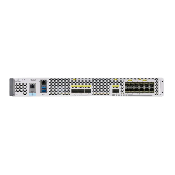
Cisco Catalyst 8500 Series Hardware Installation Manual
Edge platforms
Hide thumbs
Also See for Catalyst 8500 Series:
- Hardware installation manual (100 pages) ,
- Regulatory compliance and safety information manual (31 pages) ,
- Manual (18 pages)
Table of Contents
Advertisement
Quick Links
Advertisement
Table of Contents


Need help?
Do you have a question about the Catalyst 8500 Series and is the answer not in the manual?
Questions and answers