Advertisement

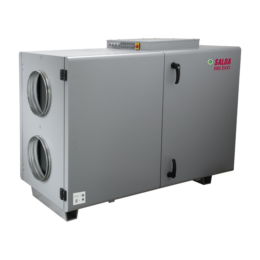
RIS 12003500 H EKO 3.0
EN
MOUNTING AND INSTALLATION INSTRUCTION

Advertisement

Table of Contents
loading

Summary of Contents for Salda RIS 1200 HEL EKO 3.0

  • Page 1 RIS 12003500 H EKO 3.0 MOUNTING AND INSTALLATION INSTRUCTION...
  • Page 2: Table Of Contents

    1. CONTENT 2. SYMBOLS AND MARKING 3. SAFETY INSTRUCTIONS AND PRECAUTIONS 4. INFORMATION ABOUT THE PRODUCT 4.1. DESCRIPTION 4.2. DIMENSIONS AND WEIGHT 4.3. TECHNICAL DATA 4.4. OPERATING CONDITIONS 4.5. STANDART PACKAGE OF COMPONENTS 4.6. DESCRIPTION OF COMPONENTS 5. INSTALLATION 5.1. RECEPTION OF GOODS 5.2.
  • Page 3: Symbols And Marking

    2. SYMBOLS AND MARKING Warning – pay attention Additional information Apply the auxiliary label on the unit (on an easily accessible location) or on the dashed location of the technical manual in order to keep the important information about the unit. Figure.
  • Page 4 Figure. 2.9. Technical label place and air duct indication RIS 3500 H Figure. 2.10. Technical label place and air duct indication RIS 3500 H EKO 3.0 (right version) EKO 3.0 (left version) NOTE. Ducts are not the part of the unit. | EN RIS 1200-3500 H EKO 3.0 v2021.1...
  • Page 5: Safety Instructions And Precautions

    3. SAFETY INSTRUCTIONS AND PRECAUTIONS Read these instructions very carefully before installing and using this equipment. Installation, connection and maintenance should be carried out Main safety rules Danger • of the device have stopped. • Make sure that the fans are not accessible through air ducts or branch openings. •...
  • Page 6: Information About The Product

    4. INFORMATION ABOUT THE PRODUCT 4.1. DESCRIPTION Not suitable for operation in pools, saunas and other similar premises. 4.2. DIMENSIONS AND WEIGHT Figure 4.2.1. RIS 1200 H EKO 3.0 Figure 4.2.2. RIS 1900-2200 H EKO 3.0 | EN RIS 1200-3500 H EKO 3.0 v2021.1...
  • Page 7 Figure 4.2.3. RIS 2500 H EKO 3.0 Figure 4.2.4. RIS 3500 H EKO 3.0 RIS 1200-3500 H EKO 3.0 v2021.1 EN |...
  • Page 8 RIS EKO 3.0 1200 HEL 1200 HER 1200 HWL 1200 HWR [mm] 1500 1500 1500 1500 [mm] [mm] 1000 1000 1000 1000 [mm] [mm] [mm] [mm] d/dn G1/2 G1/2 G1/2 G1/2 [mm] [mm] 1268 1268 1268 1268 [mm] [mm] [mm] [mm] [mm] [mm]...
  • Page 9 RIS EKO 3.0 2500 HEL 2500 HER 2500 HWL 2500 HWR 3500 HEL 3500 HER 3500 HWL 3500 HWR [mm] 2100 2100 2100 2100 2755 2755 2755 2755 [mm] [mm] 1355 1355 1355 1355 1600 1600 1600 1600 [mm] [mm] [mm] [mm] 1182...
  • Page 10: Technical Data

    4.3. TECHNICAL DATA RIS EKO 3.0 1200 HE 1200 HW Exhaust air fan phase/voltage [50 Hz/VAC] 1/230 1/230 [kW/A] 0,38/2,5 0,38/2,5 speed [min 3370 3370 control input [VDC] 0-10 0-10 protection class IP54 IP54 Supply air fan phase/voltage [50 Hz/VAC] 1/230 1/230 [kW/A]...
  • Page 11: Operating Conditions

    RIS EKO 3.0 2500 HE 2500 HW 3500 HE 3500 HW Exhaust air fan phase/voltage [50 Hz/VAC] 1/230 1/230 1/230 1/230 [kW/A] 0,87/3,92 0,87/3,92 1,3/5,65 1,3/5,65 speed [min 2200 2200 2390 2390 control input [VDC] 0-10 0-10 0-10 0-10 protection class IP54 IP54 IP54...
  • Page 12: Description Of Components

    4.6. DESCRIPTION OF COMPONENTS Figure 4.6.1. RIS 1200 H EKO 3.0 Figure 4.6.2. RIS 1900-2200 H EKO 3.0 Figure 4.6.3. RIS 2500 H EKO 3.0 Figure 4.6.4. RIS 3500 H EKO 3.0 1 - Plate heat exchanger; 2 - Supply fan; 3 - Exhaust fan; 4 - By-pass damper | EN RIS 1200-3500 H EKO 3.0 v2021.1...
  • Page 13: Installation

    5. INSTALLATION 5.1. RECEPTION OF GOODS Each device is carefully checked before transportation. When receiving the goods, checking the devices for any damage made during transporta- tion is recommended. If any damage to the unit is observed, immediately contact the representatives of a transport company. Please inform the representative of the manufacturer, if any deviation of the device is noticed.
  • Page 14: Unpacking

    Figure 5.2.2. Lifting In order to prevent damage to the casing, only a product placed on a pallet should be lifted. 5.3. UNPACKING Accessories may be packed together with the product. Prior to transporting the unit, the accessories should be unpacked •...
  • Page 15 Figure 5.4.2. RIS 2500 H EKO 3.0 Figure 5.4.3. RIS 3500 H EKO 3.0 * KE1 - only in electrical version; * KV1 - used in water version; ** Possible to control. THE LIST OF COMPONENTS Plate heat exchanger Supply air fan Exhaust fan Exhaust air temperature sensor Supply air temperature sensor...
  • Page 16: Mounting

    POSIBLE PCB INPUTS/OUTPUTS Fire alarm Alarm indication output Working indication output 5.5. MOUNTING • • When connecting air ducts, consider the labels on the casing of the unit. • Before connecting to the air duct system, the connection openings of ventilation unit should be closed. •...
  • Page 17: Drainage

    • Install the supporting legs. • The units are assembled from separate sections. • • Figure 5.5.2.1. Floor mounting 5.5.3. DRAINAGE Figure 5.5.3.1. Drainage installation 5.6. CONNECTION OF THE AIR DUCT • • • and noise level, you can increase the diameter. •...
  • Page 18: Start-Up Recommendations

    • • • • made during transportation. • The manufacturer does not assume any liability for personal injuries and property damage due to nonconformance with the provided instructions. 5.8. START-UP RECOMMENDATIONS 5.8.1. SYSTEM PROTECTION RIS EKO 3.0 1200 HE 1200 HW 1900 HE 1900 HW 2200 HE...
  • Page 19: Maintenance

    6. MAINTENANCE 6.1. SAFETY INSTRUCTION Unplug the unit from the mains before opening the door (disconnect the power plug from the outlet or in case an automatic circuit breaker installed, disconnect it as well. Make sure that it cannot be turned on by third parties) and wait until the fans completely stop (for about 2 min.).
  • Page 20: Filters Maintenance

    6.4. FILTERS MAINTENANCE direction. tion manual or on our website www.salda.lt 6.5. FANS MAINTENANCE • • The fan should be inspected and cleaned at least once per year. • • Proceed to maintenance and repair after any fan rotation is stopped.
  • Page 21: Heater Maintenance

    Figure 6.6.2. RIS 2500 H EKO 3.0 Figure 6.6.3. RIS 3500 H EKO 3.0 6.7. HEATER MAINTENANCE • • • • • If necessary, electric heater can be removed. Disconnect the electrical connector from the heater and remove the heater. Figure 6.7.1.
  • Page 22: Control Board Maintenance

    Figure 6.7.2. RIS 2500 H EKO 3.0 Figure 6.7.3. RIS 3500 H EKO 3.0 6.8. CONTROL BOARD MAINTENANCE • • • Remove the control box cover. • • Remove control board. • and connector to corresponding connection terminal and connector. | EN RIS 1200-3500 H EKO 3.0 v2021.1...
  • Page 23: Control

    BMS over Modbus TCP/IP FLEX BMS over BACnet TCP/IP 7.2. DEVICE FUNCTIONS WEB application and SALDA AIR mobile application. Refer to the instruction manual of the existing control device for unit control instructions. RIS 1200-3500 H EKO 3.0 v2021.1 EN |...
  • Page 24: Accessories

    8. ACCESSORIES RIS EKO 3.0 1200 HE 1200 HW Roof RIS 1200 H EKO 3.0 ACC000043 ACC000043 Roofs Roof CB 315 ACC004737 ACC004737 ABV 315 ACC000057 ACC000057 Outlet covers LSVF 315 FIT000308 FIT000308 VVP45.10-0.63 ACC000140 Valves VXP45.10-0.63 ACC000143 CB 315 C2+DE ACC000165 ACC000165 CB 315 C4+DE...
  • Page 25 Sensor C02 duct S-KCO2 ACC000277 ACC000277 Sensor CO2 room S-RCO2-F2 ACC000278 ACC000278 External sensors Pressure transmitter S-1141 ACC004375 ACC004375 Actuator for damper LM230A-TP ACC000311 ACC000311 Actuator for damper LF230 ACC000309 Actuators ACC000317 ACC000318 ACC000318 EKA NV 315-1.0-1f PH ACC003906 ACC003906 EKA NV 315-1.2-1f PH ACC003908 ACC003908...
  • Page 26 Filter set RIS 1900 H/V EKO 3.0 Filter sets ACC004886 ACC004886 ACC004886 ACC004886 (ePM10-50+ePM1-70-2pcs.) CB 400 C2+DE ACC000179 ACC000179 ACC000179 ACC000179 CB 400 C4+DE ACC000180 ACC000180 ACC000180 ACC000180 CB 400 F4+DE ACC000181 ACC000181 ACC000181 ACC000181 CB 400 H1 ACC000182 ACC000182 CB 400 H1+C2+DE ACC000183 ACC000183...
  • Page 27 SM230A-TP ACC000315 ACC000315 ACC000315 ACC000315 NF230A ACC000313 ACC000313 Actuators ACC000317 ACC000317 ACC000318 ACC000318 ACC000318 ACC000318 EKA NV 400-1.0-1f PH ACC003924 ACC003924 ACC003924 ACC003924 EKA NV 400-1.2-1f PH ACC003925 ACC003925 ACC003925 ACC003925 EKA NV 400-12.0-3f PH ACC000384 ACC000384 ACC000384 ACC000384 EKA NV 400-15.0-3f PH ACC000385 ACC000385 ACC000385...
  • Page 28 CB 600x350 C2+DE ACC000212 ACC000212 CB 600x350 C4+DE ACC000213 ACC000213 CB 600x350 F4+DE ACC000214 ACC000214 CB 600x350 H1 ACC000215 CB 600x350 H1+C2+DE ACC000216 CB 600x350 H1+C4+DE ACC000217 CB 600x350 H1+F4+DE ACC000218 CB 600x350 H2 ACC000219 CB 600x350 H2+C2+DE ACC000220 CB 600x350 H2+C4+DE ACC000221 CB 600x350 H2+F4+DE ACC000222...
  • Page 29: Connection Of Accessories

    EKS NV 60x35/12-3f PH ACC000436 ACC000436 EKS NV 60x35/15-3f PH ACC000437 ACC000437 EKS NV 60x35/3-3f PH ACC000438 ACC000438 EKS NV 60x35/6-3f PH ACC000439 ACC000439 EKS NV 60x35/9-3f PH ACC000440 ACC000440 EKS NV 80x50/12-3f PH ACC000447 ACC000447 El.heaters EKS NV 80x50/15-3f PH ACC000448 ACC000448 EKS NV 80x50/18-3f PH...
  • Page 30: Co2 Concentration According To Pettenkofer Limit

    The CO2 transmitter is installed in the extract air duct or room. 8.1.3. ROOM CO2 TRANSMITTER INSTALLATION RECOMMENDATION 5 0 c m i n . min. 60 cm max. 400m If the duct CO2 transmitter is used, it must be installed in the extract air duct. To install duct transmitters, hole drilling tools are required .
  • Page 31: Connection Of Remote Control Panel Or Modbus

    Wiring diagram for RIS 1200-2200 HW EKO 3.0 M2 – Spring-return damper actuator. M3 – Open/Close damper actuator. Upon activation of outputs X16:17, X16:20, the dampers open, Upon is deactivated, the supply air damper closes. 8.1.6. CONNECTION OF REMOTE CONTROL PANEL OR MODBUS 8.1.7.
  • Page 32 Figure 8.1.7.1. RIS 1200-2200 H EKO 3.0 Figure 8.1.7.2. RIS 2500-3500 H EKO 3.0 | EN RIS 1200-3500 H EKO 3.0 v2021.1...
  • Page 33: Recommended Scheme For Connection Of Internal And External Components

    8.1.8. RECOMMENDED SCHEME FOR CONNECTION OF INTERNAL AND EXTERNAL COMPONENTS Figure 8.1.9. RIS 1200 HE EKO 3.0 RIS 1200-3500 H EKO 3.0 v2021.1 EN |...
  • Page 34 Figure 8.1.10. | EN RIS 1200-3500 H EKO 3.0 v2021.1...
  • Page 35 Figure 8.1.11. RIS 1900-2200 HE EKO 3.0 RIS 1200-3500 H EKO 3.0 v2021.1 EN |...
  • Page 36 Figure 8.1.12. | EN RIS 1200-3500 H EKO 3.0 v2021.1...
  • Page 37 PE N 2 4 6 Figure 8.1.13. RIS 2500 HE EKO 3.0 RIS 1200-3500 H EKO 3.0 v2021.1 EN |...
  • Page 38 PE N L1 Figure 8.1.14. | EN RIS 1200-3500 H EKO 3.0 v2021.1...
  • Page 39 PE N Figure 8.1.15. RIS 3500 HE EKO 3.0 RIS 1200-3500 H EKO 3.0 v2021.1 EN |...
  • Page 40 PE N L1 Figure 8.1.16. | EN RIS 1200-3500 H EKO 3.0 v2021.1...
  • Page 41: Possible Faults And Troubleshooting

    9. POSSIBLE FAULTS AND TROUBLESHOOTING FAILURE CAUSE EXPLANATION / CORRECTIVE ACTIONS No supply voltage Unit is not operating leakage relay is active (if installed by the installer) matic Check if fans are rotating protection Air supply heater or pre-heater is not operat- ing or malfunctioning (if installed) Possible heater or unit failure.
  • Page 42: Ecodesign Data Table

    10. ECODESIGN DATA TABLE RIS EKO 3.0 1200 HE 1200 HW 1900 HE 1900 HW Declared typology bidirectional bidirectional bidirectional bidirectional Type of drive Variable Variable Variable Variable Type of HRS recuperative recuperative recuperative recuperative 83,9 83,9 84,3 84,3 /s ] 0,33 0,33 0,42...
  • Page 43 RIS EKO 3.0 3500 HE 3500 HW Declared typology bidirectional bidirectional Type of drive Variable Variable Type of HRS recuperative recuperative 79,6 79,6 /s ] 0,99 0,99 [ kW ] 2,29 2,29 SFPint [ W/(m /s) ] 1137 1137 Face velocity [ m/s ] 1,65 1,65...
  • Page 44: Declaration Of Confimity

    11. DECLARATION OF CONFIMITY Manufacturer SALDA, UAB LT-78109 Šiauliai, Lithuania Tel.: +370 41 540415 www.salda.lt RIS * EKO 3.0 Machinery Directive 2006/42/EC EMC Directive 2014/30/EU Low Voltage Directive 2014/35/EU Ecodesign Directive 2009/125/EC RoHS 2 Directive 2011/65/EU Ecodesign requirements for ventilation units Nr. 1253/2014 Energy labeling of residential units Nr.
  • Page 45: Warranty

    12. WARRANTY date. such damage. damaged by installing the control system. 4.1. mechanical damage; 4.2. damage caused by entering outside objects, materials, liquids; lation and mounting regulations, deliberate or careless users or third-party behavior. days and deliver the equipment to manufacturer. Delivery costs should be covered by customer. Manufacturer reserves the right to change this technical passport any time without prior notice, if some typographic errors or inaccurate information is found, as well as after improving the apps and/or the devices.
  • Page 46 RIS 1200-3500 H EKO 3.0 v2021.1...
  • Page 47 RIS 1200-3500 H EKO 3.0 v2021.1...
  • Page 48 Once per year** Every 3-4 Filter replacement months** Look at the product label. ** - At least. NOTE. The customer shall be required to complete the Product Maintenance Table. MANUALS IN OTHER LANGUAGES https://select.salda.lt/file/ https://select.salda.lt/file/ https://select.salda.lt/file/ https://select.salda.lt/file/ https://select.salda.lt/file/ ris1200-3500hekode ris1200-3500hekodk ris1200-3500hekofr ris1200-3500hekolt ris1200-3500hekopl https://select.salda.lt/file/...

Table of Contents