Advertisement
Quick Links
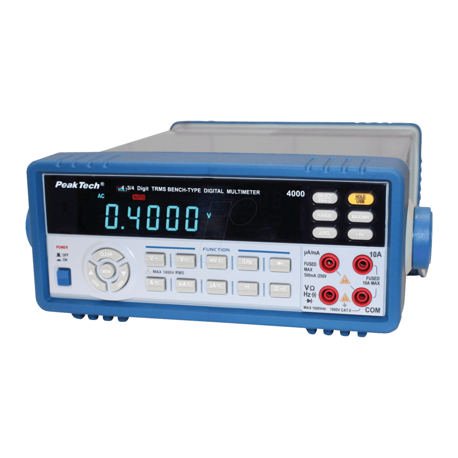
Procedure of calibration for PeakTech
1. Checking its basic functions
Place the rotating switch on the AC Volt position when the power supply is turned on. All of the
buttons shall display and sound properly when you press them. The sound and loudness from the
buzzers shall be mellow and sonorous. VFD shall display the correct symbol when you place the
switch on every tested position. Table 1 shows the symbols displayed when the switch is placed
on every position.
Table 1: symbols displayed on LCD when the switch is placed on every position (note: it is
possible that the '-' in bracket isn't displayed)
Position
Symbol
AC Volt
AC, AUTO, V, VOLT
DC Volt
DC, AUTO, V, VOLT, (-)
mV
DC, AUTO, mV, VOLT, (-)
Logic frequency
AUTO, Hz, FREQ
Diode
V,
Resistance
AUTO, MΩ, OHM
2. Entering into the Calibration Mode
Firstly press and hold the Calibration button on the bottom of the meter. Switch on the meter; and
then release the Calibration button immediately. The meter will enter in the Calibration Mode. Its
feature is that the meter will immediately enter into the Manual range (the MANUAL displayed)
when it is turned on; but it will enter into the AUTO range (the AUTO displayed) if it isn't in the
Calibration mode.
3. Zeroing
Press the ~Hz button. Now the applications in the meter will perform the zeroing process
automatically. However, the zeroing will not be performed until its digitals have been displayed
stably. Otherwise, zero drift will take place when the zeroing has finished. The zeroing for every
range corresponding to the positions shall be performed. When performing the zero, the inputs
shall be short or open depending on the positions. For the AC voltage and current, waiting time
for digital display is so longer that the zeroing shall not be performed until the digitals has been
displayed. Otherwise, precise zeroing cannot be achieved. To reduce waiting time and increase
the efficiency, you may use the method that a batch of meters will be zeroed. Table 2 shows the
modes, ranges and input conditions corresponding to every position required to be zeroed.
4. Calibrating the ranges
The range shall not be calibrated until the zeroing has finished. When calibrating the meter,
different standard signals (or standard elements such as resistance and capacitance) shall be
input (or connected) depending on the positions and ranges. Then press the HOLD button when
the digitals on the meter have been displayed stably. Now the applications in the meter start to
perform the calibration automatically. If the meter displays the OL when these signals (or
elements) are input (or connected), press the HOLD button firstly. When the digitals are displayed
stably, press the HOLD button one time. When pressing the HOLD button, the digitals on meter
shall be basically equal to standard signals or element values (the difference shall not exceed 2
numbers). If the difference is too bigger, press and hold the HOLD button until the digital is
basically equal to the signal or value. The table 3 shows the modes, ranges and input
corresponding to the positions required to be calibrated. Since the capacitance for high frequency
compensation can affect on the measure of capacitance, the calibration on the capacitance can be
performed only when the calibration on high frequency compensation has finished. When
calibrating the resistance range of 50MΩ, firstly connect 40MΩ of standard resistance, and then
press the HOLD button. When the LCD displays the E, This resistance shall be replaced with
20MΩ of standard resistance, and then press the HOLD button.
Position
Symbol
Capacitance
AUTO, nF,
µA
DC, AUTO,µA, AMP,(-)
mA
DC, AUTO, mA, AMP,(-)
A
DC, AUTO, A, AMP,(-)
®
4000
Advertisement

Related Manuals for PeakTech 4000


Summary of Contents for PeakTech 4000
- Page 1 Procedure of calibration for PeakTech ® 4000 1. Checking its basic functions Place the rotating switch on the AC Volt position when the power supply is turned on. All of the buttons shall display and sound properly when you press them. The sound and loudness from the buzzers shall be mellow and sonorous.
- Page 2 ® Table 2: the schedule of the zeroing for PeakTech 4000 5. Position Mode (by the Select Range (by the Input condition Method button) Range button) Short between the Press the ~Hz VΩHz and COM button 500V 1000V 500V 1000V...
- Page 3 ® Table 3: the schedule of range calibration for PeakTech 4000 Mode (by the Range (by the Standard Signal output Calibration Position Select button) Range button) signal and Method element value ~4V/60Hz N / A ~40V/60Hz VΩHz port 500V ~400V/60Hz...
- Page 4 5. Calibrating high frequency High frequency may be calibrated only when the meter is in the normal operating conditions rather than the Calibration mode. Only AC Volt position shall be calibrated for high frequency; high frequency performance on other positions shall be ensured by means of the circuits. Parts of compensation capacitances (C4, C5, C6, C7) have been soldered into the circuit board where retains four positions (C4, C5, C6, C7) for soldering four additional capacitances.
- Page 5 9. Measure and check of linear frequency Place the switch on the AC Volt (~V) position and 5 V range. Input the 500mV/200KHz of signal into the VΩHz and COM ports. By pressing the ~Hz button, the meter shall display proper frequency at second section and the error shall be ±3 (±0.006%±2).
Need help?
Do you have a question about the 4000 and is the answer not in the manual?
Questions and answers