
Related Manuals for PeakTech 3355


Summary of Contents for PeakTech 3355
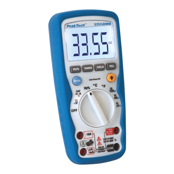
- Page 1 ® PeakTech 3355 / 3360 Bedienungsanleitung / operation manual / Mode d’emploi / Istruzioni per l'uso / Manual de instrucciones Digital Multimeter / Multimètre digital / Multimetro digitale / Multímetro digital...
-
Page 2: Safety Precautions
1. Safety Precautions This product complies with the requirements of the following European Community Directives: 2004/108/EC (Electromagnetic Compatibility) and 2006/95/EC (Low Voltage) as amended by 2004/22/EC (CE-Marking). Overvoltage category III 1000V; over- voltage category IV 600V; pollution degree 2. CAT I: For signal level, telecommunication, electronic with small transient over voltage CAT II:... - Page 3 The meter is designed to withstand the stated max voltages. If it is not possible to exclude without that impulses, transients, disturbance or for other reasons, these voltages are exceeded a suitable prescale (10:1) must be used. Replace a defective fuse only with a fuse of the original rating. Never short-circuit fuse or fuse holding.
- Page 4 400 mA AC/DC 1000 V / 0,5 A (fused) A range 10 A AC/DC 1000 V / 10 A (fused) Frequency, Resistance, 600 V AC/DC (P 3355) Capacitance, Duty Cycle, Diode 1000 V AC/DC (P 3360) test, Continuity and Temperature -36-...
- Page 5 1.2. Safety Symbols This symbol adjacent to another symbol, terminal or operating device indicates that the operator must refer to an explanation in the operating instructions to avoid personal injury or damage to the meter. This symbol advices the user that the terminals so marked must not be connected to a circuit point at which the voltage, with respect to earth ground, exceeds (in this case) 1000 V AC or VDC...
-
Page 6: Technical Data
2. Technical Data 2.1. Specifications Display P 3355 26 mm , 3 ¾ digit, 4000 counts with automatic polarity indication backlight P 3360 19 mm, 4 ¾... - Page 7 Auto / manual Ranging Auto power off: about 15 min. P 3360 : It is possible to turn off the APO (find on page 53) Overload protection: on all ranges measuring functions: True RMS measurement (only P 3360) Auto- or manual range selection Data Hold Relative zero Min/Max and Peak-Hold (only P 3360)
- Page 8 ± 1,0% v.M. + 3 dgt 10 mV 100 mV 1000 Overload protection 1000V AC/DC Input Impedance: (P 3355) 7,8 MΩ / (P 3360) 3 MΩ AC Response: (P 3355) 50 to 400Hz / (P 3360) 50 to 1000Hz -40-...
- Page 9 400 mA µA Overload protection: 0,5A / 1000V and 10A / 1000V Max. input: 400mA DC on mA – Range and 10A on A – Range AC Response : (P 3355) 50 to 400Hz / (P 3360) 50 to 1000Hz -41-...
- Page 10 Resistance Model Range Resolution Accuracy P 3355 100 mΩ ± 1,2% rdg. + 4 dgt. Ω 4 kΩ ± 1,0% rdg. + 2 dgt. Ω 40 kΩ Ω ± 1,2% rdg. + 2 dgt 400 kΩ Ω 4 MΩ 1 kΩ...
-
Page 11: Resolution Accuracy
40 MHz 1 kHz 100 MHz 10 kHz not specified Overload protection: 600 V DC/AC Sensitivity: <0,5V RMS at ≤1MHz / >3V RMS at >1MHz (P 3355) Sensitivity: <0,8V RMS at ≤100kHz / >5V RMS at >100kHz (P 3360) -43-... - Page 12 Duty cycle Model Range Resolution Accuracy P 3355 0,1...99,9 % 0,1% ± 1,2% rdg. +2 dgt. Pulse width: >100 µs,< 100 ms Frequency: 5Hz-150kHz Sensitivity: <0,5V P 3360 0,1...99,9 % 0,01% +/- 1,2% rdg. +2 dgt. +/-50 dgt. 0,01% 4-20mA% -25...125%...
- Page 13 Continuity Model Audible Threshold Test current P 3355 <0,3 < 150 Ω P 3360 < 0,35 mA < 35 Ω Overload protection: 600 V DC/AC Diode Test Model Test current Open circuit voltage P 3355 0,3 mA 1,5 V P 3360...
- Page 14 P 3360 LCD Display Relative pushbutton Range pushbutton Mode pushbutton Function switch µA/mA/10 A (positive) input jack COM (negative) input jack Positive input jack for voltage, Hz, Duty cycle, Ohms, Diode, Continuity, Capacitance, and temperature measurements Data Hold and Backlight pushbutton PEAK button MIN / MAX button -47-...
-
Page 15: Operating Instructions
3.1. Symbols in the LCD Display •))) Continuity ->|- Diode test Battery status nano (10 micro (10 µ milli (10 current kilo (10 capacitance (Farads) mega (10 Resistance Ω Frequency Duty cycle Alternating current Direct current ° F Temperature in Fahrenheit °... - Page 16 The backlight function is used to illuminate the display when the meter is used at night or in dimly lighted area. 1. Press the "HOLD" button (P 3355) or the backlight button (P 3360) for more than 2 seconds, the "HOLD" indicator will appear and backlight will be activated.
- Page 17 2. Press the "HOLD" button momentarily to remove the "HOLD" function. (P 3360). 3. Press the "HOLD" button (P 3355) or the backlight button (P 3355) for more than 2 seconds to remove the backlight function. 4. Press the "HOLD" button momentarily to remove the "HOLD"...
- Page 18 5.2. Data Hold The data hold function allows the meter to "freeze" a measurement for later reference. 1. Press the "HOLD" button to freeze the display, the "HOLD" indicator will appear in the display. 2. Press the "HOLD" button to return to normal operation. 5.3.
- Page 19 5.4. AC voltage measurements Warning: Risk of Electrocution. The probe tips may not be long enough to contact the live parts inside some 230 V outlets for appliances because the contacts are recessed deep in the outlets. As a result, the reading may show 0 volts when the outlet actually has voltage on it.
- Page 20 3. For current measurements up to 400 mA DC, set the function switch to the "mA" position and insert the red test lead banana plug into the mA-µA jack. 4. For current measurements up to 10 A DC, set the function switch to the 10 A position and insert the red test lead banana plug into the 10 A jack.
- Page 21 4. For current measurements up to 10 A DC, set the function switch to the 10 A position and insert the red test lead banana plug into the 10 A jack. 5. Press the “MODE” button until "AC" appears in the display. 6.
- Page 22 4. Touch the test probe tips to the circuit or wire you wish to check. 5. If the resistance is less than 150 ohms (P 3355) or 35 ohms (P 3360), the audible signal will sound. The display will also show the actual resistance.
- Page 23 3. Insert the black test lead banana plug into the negative COM jack and the red test lead banana plug into the positive Ω jack. 4. Touch the test probe tips to the diode or semiconductor junction you wish to test. Note the meter reading. 5.
- Page 24 5.11. Capacitance measurements Warning: To avoid electric shock, disconnect power to the unit under test and discharge capacitors before taking capacitance measurements. Remove the batteries and unplug the line cords. 1. Set the function switch to the "CAP" ┤├ position. 2.
-
Page 25: Replacing The Fuses
6. Replacing the fuses WARNING! To avoid electric shock, disconnect all the test probes before removing the fuse. Replace only with the same type of fuse. Not note remove the top cover. Service should be performed only by qualified personnel. CAUTION! For continued protection against fire or other hazard, replace only with fuse of the specified voltage and current ratings. -
Page 26: Maintenance
WARNING! Do not operate your meter until the back cover is in place and fully closed. 7. Maintenance Warning: To avoid electric shock, disconnect the test leads from any source of voltage before removing the back cover or the battery/fuse door. Warning: To avoid electric shock, do not operate your meter until the battery/ fuse door are in place and fastened securely. -
Page 27: Troubleshooting
8. Troubleshooting There may be times when your meter does not operate properly. Here are some common problems that you may have and some easy solutions to them. Meter does not operate: 1. Always read all the instructions in this manual before use. 2. - Page 28 Warning: To avoid electric shock, do not operate your meter until the back cover and the battery / fuse door is in place and fastened securely. Note: If your meter does not work properly, check the fuses and batteries to make sure that they are still good and that they are properly inserted.
- Page 29 We herewith confirm, that the units are calibrated by the factory according to the specifications as per the technical specifications. We recommend to calibrate the unit again, after 1 year. ® © PeakTech 01/2013/Ho/Pt. -62-...
Need help?
Do you have a question about the 3355 and is the answer not in the manual?
Questions and answers