Advertisement
Quick Links
INSTALLATION MANUAL
Level of Difficulty
Moderate
Weight Capacity
Gross trailer weight (GTW)
Vertical load
Parts List
Item Qty Description
1
1
Main body / Head assembly
2
1
Leg weldment
3
1
Leg weldment (with INS label)
4
1
Handle assembly
5
1
Handle lock bar
6
2
Button head cap screw,
M8 - 1.25" x 30
7
2
Lock washer, M8
8
1
Latch spring
9
1
Safety latch pin, 3/8"
10
4
Hex bolt, M14
11
4
Lock washer, M14
12
4
Flat washer, M14
13
4
Nylock nut, M14
14
4
Base rail mounting clip
15
4
Base rail mounting pin,
1/2" diameter
Tools Required
Ratchet
Torque wrench
Socket set
--
Torque Specifications
M8 bolt
16 ft-lbs.
M14 bolt
100 ft-lbs.
Use above torque setting unless otherwise noted
Product Registration
CURT Group stands behind our products
with industry-leading warranties. Provide
feedback and help us to improve our
products by registering your purchase at:
warranty.curtgroup.com/surveys
CURTMFG.COM
•
NEED ASSISTANCE?
DANGER ZONE PRECAUTIONS
Block all trailer tires in front and behind with appropriate wheel chocks. Do not substitute
objects such as, but not limited to: stones, wood blocks, etc. Front trailer lifting jacks must be
supporting the trailer and resting on a firm and level surface.
Towing vehicle must be stationary with automatic transmission
in park (manual in neutral), emergency brake applied and engine off.
30,000 lbs.
7,500 lbs.
WARNING
Never exceed the vehicle manufacturer's recommended towing capacity. Trailer and contents
combined must not exceed tow vehicle, hitch and / or trailer tow ratings. Exceeding rated
capacity may result in separation. Exceeding rated capacity may result in damage to 5th wheel
hitch, towing vehicle, trailer and or cause serious injury or death.
Fully instruct and demonstrate the operation of this 5th wheel hitch to the end user. Include the
importance of observing all warnings contained herein, including warning labels on 5th wheel
hitch main body. Provide this manual in its entirety to the end user. Serious injury or death may
result if the warnings above are not observed.
To avoid serious injury, do not expose hands, body parts or clothing between the truck and
trailer or the truck's bed sides and trailer. Extreme care should be observed to avoid serious
injury to self, property and observers.
Never position yourself or others under the trailer's kingpin area (danger zone) during coupling
and uncoupling. If for any reason you must position any part of your body under the trailer,
between the truck and the trailer or between the trailer's kingpin and 5th wheel hitch, you must
follow the steps in the 'Danger Zone Precautions' section above. Improperly coupled trailers can
separate and drop without notice.
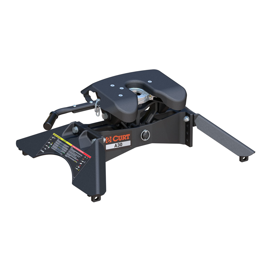
Product Photo
NOTICE
Before you begin installation, read all instructions thoroughly.
Proper tools will improve the quality of installation and reduce the time required.
To help prevent damage to the product or vehicle, refer to the specified
torque specifications when securing hardware during the installation process.
•
877.287.8634
•
16190-INS-RA
•
PAGE 1
16190
Advertisement

Related Manuals for Curt Group 16190


Summary of Contents for Curt Group 16190
- Page 1 16 ft-lbs. M14 bolt 100 ft-lbs. Use above torque setting unless otherwise noted Product Registration CURT Group stands behind our products with industry-leading warranties. Provide feedback and help us to improve our NOTICE products by registering your purchase at: Before you begin installation, read all instructions thoroughly.
-
Page 2: Main Body Assembly
5th wheel, assemble the legs to the main body using the appropriate unlock position. Keep hands clear of the jaws at all time. holes. Occasionally, the trailer's kingpin pin box will require adjustment to facilitate correct ride height. CURTMFG.COM • NEED ASSISTANCE? • 877.287.8634 • 16190-INS-RA • PAGE 2... - Page 3 Check to rear edge of base rail manufacturer's specifications. Continue with the installation for obstructions before drilling by tightening the bolts to 100 ft-lbs. CURTMFG.COM • NEED ASSISTANCE? • 877.287.8634 • 16190-INS-RA • PAGE 3...
-
Page 4: Handle Assembly
(#9), locking the handle in the tow position. Position the handle assembly so the first M8 cap screw (#6) and lock washer (#7) can be dropped into position behind the latch spring. Detail B Detail A CURTMFG.COM • NEED ASSISTANCE? • 877.287.8634 • 16190-INS-RA • PAGE 4... - Page 5 5th wheel. Always ensure the jaws are open and unobstructed prior to 4" coupling to your trailer's kingpin. 1/2" CURTMFG.COM • NEED ASSISTANCE? • 877.287.8634 • 16190-INS-RA • PAGE 5...
- Page 6 5th wheel unit be used if damage exists. If are ready to couple. no damage exists, review coupling instructions and repeat procedure. CURTMFG.COM • NEED ASSISTANCE? • 877.287.8634 • 16190-INS-RA • PAGE 6...
- Page 7 Hold the position by applying your vehicle's parking brake is ready to be recoupled the next time you tow. before putting the vehicle in park and releasing the standard brake. CURTMFG.COM • NEED ASSISTANCE? • 877.287.8634 • 16190-INS-RA • PAGE 7...
- Page 8 1. Place the main body, still attached loosely to the legs, into the base rails 2. Insert the four base rail pins & clips 3. Re-torque the four M14 hex bolts to 100 ft-lbs. CURTMFG.COM • NEED ASSISTANCE? • 877.287.8634 • 16190-INS-RA • PAGE 8...
-
Page 9: Maintenance
Spray exposed surfaces with a light coat of rust inhibitor before long term storage. CURTMFG.COM • NEED ASSISTANCE? • 877.287.8634 • 16190-INS-RA • PAGE 9...
Need help?
Do you have a question about the 16190 and is the answer not in the manual?
Questions and answers