Advertisement
Quick Links
INSTALLATION MANUAL
Level of Difficulty
Moderate
Installation difficulty levels are based on time
and effort involved and may vary depending on
the installer level of expertise, condition of the
vehicle and proper tools and equipment.
Max Capacity Without Spring Bars
Gross trailer weight (GTW)
Tongue weight (TW)
When spring bars are not used, the weight
rating is dependent upon the trailer ball
manufacturer's weight ratings. Do not exceed
the maximum weight rating of the trailer ball.
Max Capacity With Spring Bars
Gross trailer weight
8,000 - 10,000 lbs.
Tongue weight
800 - 1,000 lbs.
The tongue weight rating of the spring bars
represents the capacity of a pair of bars, not
an individual bar. Always use a pair of spring
bars and be sure they are rated the same.
Parts List
Item Qty Description
1
1
Hitch head
2
1
Adjustable shank
3
2
Spring trunnion bar
4
2
Spring bar support bracket
5
1
Snap-up handle
6
2
Head tilt spacer
7
1
Hex bolt, 3/4"-10 x 5"
8
2
Nylock nut, 3/4"-10
9
1
Hex bolt, 3/4"-10 x 4"
10
2
Wire lock lynch pin
11
1
Hitch pin & clip, 5/8"
Tools Required
Ratchet
Socket set
Torque wrench
Tape measure
Product Registration and Warranty
CURT stands behind our products with
industry-leading warranties. To get copies
of the product warranties, register your
purchase or provide feedback, visit:
warranty.curtgroup.com/surveys
CURTMFG.COM
•
PRODUCT SUPPORT: 877.287.8634
WARNING
Never exceed the vehicle manufacturer's recommended towing capacity.
The loaded ball height should never be greater than the uncoupled ball height. Front wheel overload
and loss of rear wheel traction can result and can lead to unstable handling. It can reduce
braking ability and create a tendency to jackknife when turning and braking at the same time.
If the loaded trailer ball height is greater than the uncoupled height, reduce take-up
on the spring bar, remeasure and adjust until the proper height is obtained.
10,000 lbs.
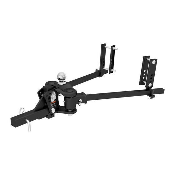
Product Photo
1,000 lbs.
NOTICE
Visit www.curtmfg.com for a full-color copy of this
instruction manual, as well as helpful videos, guides and much more!
Before you begin installation, read all instructions thoroughly.
Proper tools will improve the quality of installation and reduce the time required.
Some states require a clear view of license plates.
Remove trailer ball when not in use if it restricts view.
This product complies with regulation V-5, C.S.A. Standard D-264 and safety
requirements for connecting devices and towing systems of the State of New York.
Periodic inspection of your product should be performed
to ensure all hardware and / or components remain secure.
To help prevent damage to the product or vehicle, refer to the specified
torque specifications when securing hardware during the installation process.
Maintenance
Keep the socket-mounted ends of the spring bars and the lock pins
in the head assembly free from dirt and well lubricated. Excessive wear
in this area may indicate an overload or inadequate lubrication.
Keep the head assembly exterior clean. Do not allow dirt
or stones to lodge between the spring bars and the head.
Keep hitch parts painted to prevent rust and maintain good appearance. Do not paint over labels.
Keep lift brackets clean and lubricated to ensure ease of operation.
•
17500-INS-RC
•
08/03/2020
•
ECN7223
•
PAGE 1
17500
Advertisement

Related Manuals for Curt Group TruTrack 17500


Summary of Contents for Curt Group TruTrack 17500
- Page 1 INSTALLATION MANUAL 17500 Level of Difficulty WARNING Moderate Never exceed the vehicle manufacturer's recommended towing capacity. Installation difficulty levels are based on time The loaded ball height should never be greater than the uncoupled ball height. Front wheel overload and effort involved and may vary depending on and loss of rear wheel traction can result and can lead to unstable handling.
- Page 2 SPRING BAR WIDTH ADJUSTMENT Step 1 - Determine your spring bar width setting Step 3 - Install the sockets back into the head TruTrack is designed to work in two neutral spring bar settings to Once the cam block has been adjusted, lightly coat the balls with ™...
-
Page 3: Assembly And Installation
ASSEMBLY & INSTALLATION Parts List Item Qty Description Hitch head Adjustable shank Spring trunnion bar Spring bar support bracket Snap-up handle Head tilt spacer Hex bolt, 3/4"-10 x 5" Nylock nut, 3/4"-10 Hex bolt, 3/4"-10 x 4" Wire lock lynch pin Hitch pin &... - Page 4 Step 4 - Install the shank, hitch head and ball Step 8 - Install the spring bars Insert the adjustable shank (#2) into the receiver tube on the tow Secure the two spring bars (#3) with the wire lock lynch pins (#10). vehicle and secure with the provided hitch pin &...
- Page 5 Step 12 Step 15 Slide the L-support in between the two captive support brackets as Pry the spring bar onto the L-bracket by rotating the lift bar to vertical. shown. Set the bracket height closest to the spring bar position set With the spring bar supported by the L-bracket, remove the lift handle.
- Page 6 Before You Tow Final Installed Image - Representative Photo (#17501 shown) Check all connections listed below prior to towing: - Hitch pin & clip (securing shank to receiver) - Head to shank fasteners - Trailer ball nut - Coupler latch - Spring bar support brackets - Safety chains - Lights and turn signals...
Need help?
Do you have a question about the TruTrack 17500 and is the answer not in the manual?
Questions and answers