Table of Contents
Advertisement
Available languages
Available languages
Quick Links
Advertisement
Table of Contents

Related Manuals for ONE FITNESS RM6514


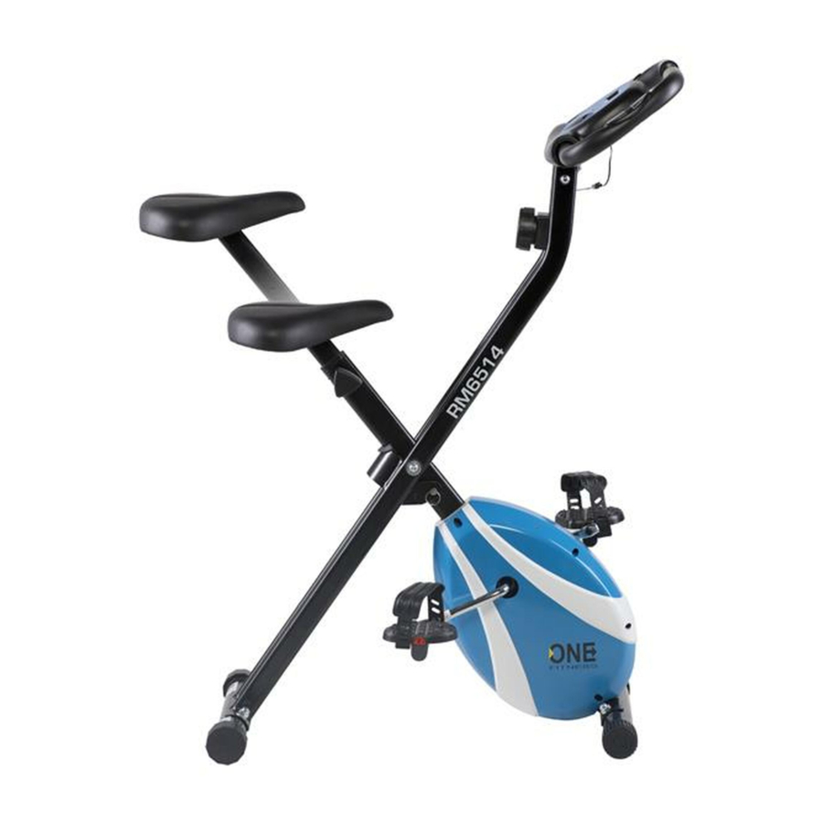
Summary of Contents for ONE FITNESS RM6514
- Page 1 RM6514...
- Page 2 Uwagi dotyczące bezpieczeństwa 1. Przed pierwszym użyciem należy zapoznać się dokładnie z instrukcją i zachować ją na przyszłość. 2. Należy uwzględnić wszystkie ostrzeżenia i środki ostrożności łącznie z etapami montażu. Z maszyny można korzystać jedynie zgodnie z jej przeznaczeniem. 3. Mając na względzie własne bezpieczeństwo, produkt należy zmontować i użytkować zgodnie z niniejszą...
-
Page 3: Lista Części
Lista części Opis Ilość Opis Ilość Rama główna Łożysko 6203Z Wspornik kierownicy Tuleja dystansująca φ21 x φ15.2 x 3.0 Kolumna komputera Nakrętka nylonowa M6 Stabilizator Φ50 x 1.5 x 360 Nakładka M10 Koło magnetyczne Φ180 x 25 Śruba M10 x 56 Podkładka łukowa Podkładka łukowa Φ10 Pokrętło regulacji oporu... - Page 4 Zaślepka przedniego wspornika Tuleja (15/16)" Zaślepka tylnego wspornika Gumowa tuleja Oś koła zamachowego Φ17 x 90 Kołnierz ośki Wał obrotowy Wkręt krzyżakowy ST4.2 x 12 Trzpień blokujący Zestaw śrub Śruba M10 x 56 4 szt. Gałka regulacji wysokości M12 1 szt. Podkładka łukowa Ø...
- Page 5 Krok 2 Montaż pedałów 1. Korby, wały pedałów i pedały są oznaczone jako „R” dla prawej i „L” dla lewej strony. 2. Włóż wał pedału lewego (20) do otworu w lewej korbie. Obróć wał pedału ręcznie w kierunku przeciwnym do ruchu wskazówek zegara, aż...
- Page 6 Krok 3 Wspornik siedziska 1. Zdejmij trzy płaskie podkładki Ø8 (38) I 3 nylonowe nakrętki M8 (42) od spodu siedziska (27). Umieść śruby prowadzące na spodzie siedziska (27) przez otwory w górnej części sztycy (25), przymocuj za pomocą trzech usuniętych płaskich podkładek Ø8 (38) i trzech nakrętek nylonowych M8 (42).
- Page 7 Krok 4 Montaż komputera 1. Usuń śruby M8 x 55 (24) Ø6 podkładki (37), podkładki łukowe Ø6 (76) ze wspornika kierownicy (2). Umieść wspornik kierownicy (2) na kolumnie komputera (3) przy pomocy usuniętych śrub M8 x 55 (24) Ø6 podkładek (37) Ø6 podkładki łukowe (76) Dokręć śruby 2.
-
Page 8: Dane Techniczne
2. Komputer wyłączy się samoczynnie po wciśnięciu dowolnego przycisku. 3. Jeśli na monitorze wyświetlają się niepełne informacje lub jest niewyraźny, należy wymienić baterie. Nie należy wymieniać tylko jednej baterii w zestawie, gdyż może to zaburzyć prawidłowy wynik pomiaru. 4. Komputer używa 2 baterii typu AAA. Konserwacja Właściwa konserwacja urządzenia wpływa znacząco na jego żywotność. -
Page 9: Safety Precautions
SAFETY PRECAUTIONS 1. Read this manual carefully before first using and retain it for future reference. 2. Observe all warnings and preacutions including assembly steps. Use it only for intended purpose. 3. Assemble and use it only according to this manual to assure your safety. Inform all other users about safe usage. - Page 10 Spare Parts List Description Description Main Frame Bearing 6203Z Spacer Bush φ21 x φ15.2 x 3.0 Handlebar Post Meter Post Nylon Nut M6 Stabilizer Φ50 x 1.5 x 360 Cap Nut M10 Magnetic Wheel Φ180 x 25 Bolt M10 x 56 Arc Washer Φ10 Arc Washer Flat Washer Φ6...
-
Page 11: Hardware Packing List
Seat Post Hexagonal Nut M6 Sensor Wire Flat Washer Seat Cushion Cross Pan Head Screw M5 x 20 End Cap for Front Stabilizer Puller Bushing (15/16)" End Cap for Rear stabilizer Rubber Bush Magnetic Wheel Axle Φ17 x 90 Axle Sleeve Cross Pan Head self-drilling screw Rotation shaft ST4.2 x 12... - Page 12 Tool: Multi hex tool with philips screwdriver Multi hex tool S19, S10, S13, S17 Step 2 Left and Right Foot Pedals Installation 1. The Cranks, Pedal Shafts, and Foot Pedals are marked “R” for Right and “L” for Left. Insert pedal shaft of Left Foot Pedal (20) into threaded hole in the left crank.
- Page 13 Step 3 Seat Post, Seat Cushion, 1. Remove three Ø8 Flat Washers (38) and three M8 Nylon Nuts (42) from underside of the Seat Cushion (27). Guide bolts on underside of the Seat Cushion (27) through holes on top of the Seat Post (25), attach with three removed Ø8 Flat Washers (38) and three M8 Nylon Nuts (42).
- Page 14 Step 4 Computer Installation 1. Remove M8 x 55 Inner Pan Head Hexagonal Bolt (24) Ø6 Flat Washer (37) Ø6 and Arc Washer (76) from Handlebar Post (2). Then attach Handlebar Post (2) onto Meter Post (3) with removed M8 x 55 Inner Pan Head Hexagonal Bolt (24) Ø6 Flat Washer (37) Ø6 and Arc Washer (76).
-
Page 15: Maintenance
2. When there is signal input, the monitor automatically on. 3. If there is a possibility to see an improper display on the monitor, please replace the batteries to have a good result. You must be to replace the batteires at the same time. 4. - Page 16 Bezpečnostní pokyny 1. Před prvním použitím je potřeba seznámit se přesně s návodem a uschovat si jej do budoucnosti. 2. Mějte na paměti všechna upozornění a bezpečnostní opatření včetně montážních kroků. Stroj lze používat pouze k určenému účelu. 3. S ohledem na vlastní bezpečnost by měl být výrobek sestaven a používán v souladu s tímto návodem.
- Page 17 Seznam částí č. Opis č. Opis Hlavní rám Ložisko 6203Z Podpěra řídítkat Distanční pouzdro φ21 x φ15.2 x 3.0 Kolumna komputera Nylonová matice M6 Stabilizator Φ50 x 1.5 x 360 Matice M10 Magnetické kolo Φ180 x 25 Šroub M10 x 56 Pružná...
- Page 18 Krytka zadního stabilizátoru Manžeta gumová Osa setrvačníku Φ17 x 90 Nákružek osky/nápravy Rotační hřídel Šroub s křížovou drážkou ST4.2 x 12 Zajišťovací kolík Sada šroubů Šroub M10 x 56 4 ks. Knoflík pro nastavení výšky M12 1 ks. Podložka pružná Ø 10 4 ks. Matice M10 4 ks.
- Page 19 Nářadí: Šroubovák a univerzální klíč S19, S10, S13, S17 Kork 2 Montáž pedálu 1. Kliky, pedálové hřídele a pedály jsou označeny jako "R" pro pravé a "L" pro levou stranu.Vložte levý hřídel pedálu (20) do otvoru v levé klice. Otáčejte pedálem rukou proti směru hodinových ručiček až...
- Page 20 Krok 3 Podpěra sedadla 1. Odstraňte tři ploché podložky Ø8 (38) a 3 nylonové matice M8 (42) ze spodní části sedadla (27). Položte vodicí šrouby na spodní část sedla (27) přes otvory v horním sloupku sedadla (25), upevněte pomocí tří odstraněných plochých podložek Ø8 (38) a tří nylonových matic M8 (42).
- Page 21 Krok 4 Montáž počítače 1. Odstraňte šrouby M8 x 55 (24) podložky Ø6 (37), podložky Ø6 (76) z držáku sloupku řízení (2). Držák sloupku řízení (2) umístěte na sloupku počítače (3) pomocí odstraněných šroubů M8 x 55 (24) Podložky Ø6 (37) Podložky pružné Ø6 (76) Utáhněte skrutky. 2.
-
Page 22: Technická Data
3. Pokud se na monitoru zobrazí neúplné informace nebo pokud jsou rozmazané, vyměňte baterie. Nenahrazujte pouze jednu sadu baterií, protože se může narušit správný výsledek měření 4. Počítač používá 2 baterie AAA Údržba Správná údržba zařízení výrazně ovlivňuje jeho životnost. Nesprávná... - Page 23 Sicherheitsanmerkungen 1. Vor dem ersten Gebrauch sollte die unten stehende Bedienungsanleitung sorgfältig durchgelesen und für die Zukunft aufbewahrt werden. 2. Es sollten alle Warnungen und Vorsichtsmaßnahmen sowie die einzelnen Montageschritte berücksichtigt werden. Nutzen Sie das Gerät nur gemäß seinem Verwendungszweck. 3.
- Page 24 Stückliste lfd. Beschreibung lfd. Beschreibung Hauptrahmen Kugellager 6203Z Lenkradstütze Distanzhülse φ21 x φ15.2 x 3.0 Säule des Computers Nylon-Mutter M6 Stabilisator Φ50 x 1.5 x 360 Aufsatz M10 Magnetrad Φ180 x 25 Schraube M10 x 56 Bogen-Unterlage Bogen-Unterlage Φ10 Drehknopf zur Unterlage Φ6 Widerstandseinstellung Drehknopf zur Höheneinstellung.des...
-
Page 25: Montage
Seil des Sensors Unterlage Sitzfläche Kreuzschlitz-Schraube M5 x 20 Blende der vorderen Abstützung Hülse (15/16)“ Blende der hinteren Abstützung Gummihülse Achse Magnetrad Φ17 x 90 Flansch der Achse Drehbare Welle Kreuzschlitz Schraube ST4.2 x 12 Arretierungsstift Schrauben-Set Schraube M10 x 56 4 stk. Bogen- Knauf für Höheneinstellung M12 1 stk. - Page 26 Werkzeuge: Universalschlüssel S19, S10, S13, S17 Schritt 2 Montage der Pedale 1. Kurbeln, Pedalwellen und Pedale sind rechts mit "R" und links mit "L" gekennzeichnet. 2. Setzen Sie die linke Pedalwelle (20) in das Loch in der linken Kurbel ein. Drehen Sie die Pedalwelle von Hand gegen den Uhrzeigersinn bis zum Anschlag.
- Page 27 Schritt 3 Stütze der Sitzfläche 1. Entfernen Sie die drei Unterlegscheiben Ø8 (38) und die 3 Nylon-M8-Muttern (42) von der Unterseite des Sitzes (27). Führen Sie die Führungsschrauben unten am Sitz (27) durch die Löcher in der oberen Sattelstütze (25) und befestigen Sie sie mit drei entfernten Unterlegscheiben Ø8 (38) und drei Nylonmuttern M8 (42).
- Page 28 Schritt 4 Montage des Computers 1. Entfernen Sie die Schrauben M8 x 55 (24) Ø6 die Unterlegscheiben (37), Ø6 und die Bogen- Unterlegscheiben (76) von der Lenksäulenhalterung (2). Setzen Sie die Lenksäulenhalterung (2) mit den entfernten M8 x 55-Schrauben (24) Ø6 Unterlegscheiben (37) Ø6 Unterlegscheiben (76) auf die Computersäule (3).
-
Page 29: Wartung
1. Der Computer wird nach 4-5 Minuten Inaktivität automatisch ausgeschaltet 2. Der Computer schaltet sich nach dem Drücken einer beliebigen Taste automatisch ein 3. Wenn auf dem Monitor unvollständige Informationen angezeigt werden oder diese nicht klar sind, tauschen Sie die Batterien aus. Ersetzen Sie keine einzelne Batterien, da dies das korrekte Messergebnis stören kann 4. - Page 30 Rozgrzewka / Warm-up / rozcvička / Warm-up FAZA ROZGRZEWKI Faza ta ma za zadanie poprawić krążenie i usprawnić pracę mięśni, a także zmniejszyć ryzyko skurczu luz kontuzji. Zaleca się wykonanie kilku ćwiczeń rozciągających zgodnie z poniższymi ilustracjami. Każde ćwiczenie rozciągające powinno trwać około 30 sekund. Nie należy nadmiernie rozciągać...
- Page 31 III. COOL-DOWN PHASE In this stage, your cardio-vascular system and muscles should get calm. Repeat the warm-up exercises, reduce your tempo and continue for approx. 5 mins. Repeat the stretching exercises, but don’t overstretch or jerk your muscles. As you get fitter, you can exercise longer and harder. It is advisable to train at least three times a week and, if possible, to space your workouts evenly throughout a week.
- Page 32 ETAPPE DER AUFWÄRMUNG Diese Etappe hilft den Kreislauf zu beschleunigen, was die Muskelübungen effektiver macht und zudem reduziert das Risiko einer Verletzung. Führen Sie vor dem Training immer eine Reihe von Streck-Übungen durch, entsprechend den unten stehenden Abbildungen. Jede Übung sollte mindestens 30 Sekunden ausgeführt werden.
-
Page 33: Karta Gwarancyjna
KARTA GWARANCYJNA Nazwa artykułu: Kod EAN: Data sprzedaży: WARUNKI GWARANCJI 1. Sprzedawca w imieniu Gwaranta udziela gwarancji na terytorium RP na okres 24 miesięcy od daty sprzedaży: hulajnoga 24 miesiące, akumulator 6 miesięcy 2. Gwarancja będzie respektowana przez sklep lub serwis po przedstawieniu przez klienta: czytelnie i poprawnie wypełnionej karty gwarancyjnej z pieczątką... -
Page 34: Guarantee Card
GUARANTEE CARD Article name: EAN code: Date of sale: GUARANTEE TERMS The Seller provides guarantee on behalf of the Guarantor within the territory of the Republic of Poland for the period of 24 months from the date of sale: electric power assisted booster 24 months, charger 6 months The Guarantee will be recognised by the shop or service centre after the client provides: - clearly and correctly filled-in guarantee card with the sale stamp and the seller’s signature - valid purchase... -
Page 35: Záruční List
ZÁRUČNÍ LIST Název produktu: EAN kód: Datum prodeje: ZÁRUČNÍ PODMÍNKY skútr 24 měsíců, Prodávající jménem Ručitele poskytuje záruku na území Polska po dobu 24 měsíců od data prodeje: baterie po dobu 6 měsíců Záruka bude respektována obchodem nebo servisem po předložení zákazníkem: čitelně... - Page 36 GARANTIEKARTE Artikelname: EAN-Code: Verkaufsdatum: GARANTIEBEDINGUNGEN 3. Der Verkäufer gewährt im Namen des Garanten eine Garantie für 24 Monate nach dem Verkaufsdatum auf dem Hoheitsgebiet der Republik Polen: Roller 24 Monate Akku 6 Monate 4. Die Garantie wird von dem Laden oder dem Service nach Vorlage: der leserlich und korrekt ausgefüllten Garantiekarte mit Verkaufsstempel und Unterschrift des Verkäufers eines gültigen Kaufnachweises für das Gerät mit dem Verkaufsdatum / Rechnung/...
- Page 37 IMPORTER: ABISAL Sp.Z.O.O., ul. Świętej Elżbiety 6, 41-905 Bytom abisal@abisal.pl www.abisal.pl...
Need help?
Do you have a question about the RM6514 and is the answer not in the manual?
Questions and answers