Table of Contents
Advertisement
Quick Links
Advertisement
Table of Contents

Related Manuals for Behringer ULTRALINK UL2000B


Summary of Contents for Behringer ULTRALINK UL2000B
- Page 1 User’s manual Version 1.0 August 2006...
-
Page 2: Important Safety Instructions
ULTRALINK UL2000B IMPORTANT SAFETY INSTRUCTIONS CAUTION: To reduce the risk of electric shock, do not remove the top cover (or the rear section). No user serviceable parts inside; refer servicing to qualified personnel. WARNING: To reduce the risk of fire or electric shock, do not expose this appliance to rain and moisture. -
Page 3: Table Of Contents
5.2 Installation in a rack ... 19 5.3 Audio connections ... 21 6. SPECIFICATIONS ... 23 6.1 ULR2000 receiver ... 23 6.2 ULB2000 transmitter ... 24 FEDERAL COMMUNICATIONS COMMISSION COMPLIANCE INFORMATION ... 25 MICROPHONE QUICK START GUIDE ... 26 ULTRALINK UL2000B... -
Page 4: Introduction
1.1 Before you get started The UL2000B was carefully packed at the factory to assure secure transportation. Should the condition of the cardboard box suggest that damage may have taken place, please inspect the unit immediately and look for physical indications of damage. -
Page 5: Initial Operation Of The Receiver
Remove the battery when the ULB2000 is not used for an extended period of time. Please ensure that only qualified personnel install and operate the ULB2000. During installation and operation, the user must be sufficiently grounded. Electrostatic charges might affect the operation of the unit. ULTRALINK UL2000B 1. INTRODUCTION... -
Page 6: Online-Registration
To arrange for warranty service, please contact the retailer from whom the equipment was purchased. Should your BEHRINGER dealer not be located in your vicinity, you may directly contact one of our subsidiaries. Corresponding contact information is included in the original equipment packaging (Global Contact Information/European Contact Information). -
Page 7: Display
COLOR CODE Each BEHRINGER ULTRALINK transmitter can be color-coded using a color ring; this way you can easily differentiate between multiple transmitters (set to different frequencies). To easily match a transmitter to a receiver, you can also attach color-coded strips to each receiver. -
Page 8: The Back
ULTRALINK UL2000B Alphanumeric display All the values and letters relevant to the operation of your ULR2000 are shown in the 6-digit alphanumeric display: for example, channel number, channel color, frequency and menu items. CHANNEL If the ULR2000 is in the basic setting (menu not selected), pressing the buttons changes the transmission channel within the selected preset. -
Page 9: Tune
With wireless signal transmission, restricted reception conditions may cause the transmission of additional noise and interference. The Squelch function lets you adjust if the ULR2000 is muted under such conditions. You can also enter the noise level that will trigger the mute function: ULTRALINK UL2000B 2.2.1 TUNE UP or DOWN buttons. -
Page 10: Auto Mute
ULTRALINK UL2000B 0 dB: the receiver is not muted low dB value: the receiver is muted only if substantial noise is transmitted with the signal high dB value: the receiver is muted even if the noise floor is low Setting a Squelch value Press the SET button to get to the menu. -
Page 11: Lock
(Preset 1) are identical to the frequencies stored in Preset 3. Loading a preset Press the SET button to get to the menu. Press the DOWN button once to get to PRESET. ULTRALINK UL2000B 2.2.6 LOCK “ ” LOCKED is shown in the display. -
Page 12: Ulb2000 Transmitter
ULTRALINK UL2000B Press the SET button again to get to the PRESET submenu. The display shows the currently active preset. Press the UP and DOWN buttons to select the desired preset. The display shows PSET 1 (2, 3 or 4). -
Page 13: Channel Setting
In this case, start anew with step 2. After a brief interruption, a second blink code is given: the LED blinks corresponding to the value selected (in this case, 4 times) with medium tempo. ULTRALINK UL2000B . . . 5 = Battery is fully charged 8 = Channel 8 is selected 3.2.2 Channel setting... -
Page 14: Preset
ULTRALINK UL2000B The value 0 is indicated by a very short blink of the LED, and you will easily tell a 0 from a 1. If no entry is made for more than 5 seconds (either on the selection switch or by pressing the POWER button), the LED blinks quickly 5 times, and the programming mode is aborted. -
Page 15: Mic Gain
In this case, start anew with step 2. After a brief break, a second blink code is given: The LED blinks according to the value selected (for example, in this case 3 times) with medium tempo. ULTRALINK UL2000B 3.2.5 Mic Gain 3. ULB2000 TRANSMITTER... -
Page 16: Auto Mute
ULTRALINK UL2000B Low Gain: the LED blinks once with medium tempo. High Gain: the LED blinks twice with medium tempo. If no entry is made for more than 5 seconds (either on the selection switch or by pressing the POWER button), the LED blinks quickly 5 times, and the programming mode is aborted. -
Page 17: Turning The Transmitter Off
The LED indicates the Mic Gain status with the corresponding number of medium-tempo blinks: ULTRALINK UL2000B 3.3 Status query 1 = battery is nearly empty . . . 5 = battery is fully loaded 1 = channel 1 is selected. . . -
Page 18: Auto Mute
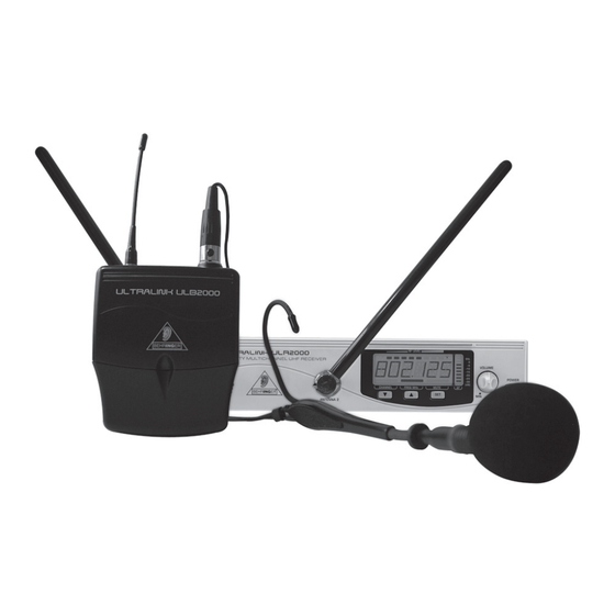
(remember: less is often more!) 4. APPLICATION EXAMPLE Fig. 4.1 shows how easy it is to use the products from the BEHRINGER ULTRALINK Series. Simply connect the balanced XLR output on the ULR2000 to the XLR input on your mixing console. -
Page 19: Installation
Mount one rack bracket on the left side of one unit and one rack bracket on the right side of the other unit. Now, both ULR2000s can be installed in a rack. ULTRALINK UL2000B 5. INSTALLATION 5.1.1 Attach the transmitter... - Page 20 ULTRALINK UL2000B To assure good reception, if possible, install the ULR2000 as high in a rack as possible, so that the antennae protrude above the upper edge of the rack. The ULR2000 requires one height unit (1 HE) for installation in a 19-inch rack. Please assure that there are additional 10 cm (4 inches) of free space in the back for connecting cables.
-
Page 21: Audio Connections
ULTRALINK UL2000B 5.3 Audio connections The audio connections on the ULR2000 are laid out electronically balanced. Of course, you can connect unbalanced equipment to the balanced connectors. Fig. 5.2: XLR connections " Fig. 5.3: 1/4 TS connector " Fig. 5.4: 1/4... - Page 22 ULTRALINK UL2000B A cable connection is required to connect the headset to the transmitter. The plug connection is provided by means of mini XLR connectors, which ensure a secure operation due to their locking mechanism. Abb.5.5: Mini XLR connector of the ULB2000...
-
Page 23: Specifications
Power supply Adapter Mains voltage Rated Current Dimensions/Weight Dimensions (W x H x D) Weight ULTRALINK UL2000B 6.1 ULR2000 receiver True Diversity wideband FM 794 - 810 MHz 320 frequencies, between 798.1 - 805.9 MHz, adjustable in 25-kHz increments 8, freely programmable and switchable <... -
Page 24: Ulb2000 Transmitter
Their use neither constitutes a claim of the trademarks by BEHRINGER nor affiliation of the trademark owners with BEHRINGER. BEHRINGER accepts no liability for any loss which may be suffered by any person who relies either wholly or in part upon any description, photograph or statement contained herein. -
Page 25: Federal Communications Commission Compliance Information
Notice: Changes or modifications made to this equipment not expressly approved by BEHRINGER International GmbH may void the FCC/ IC authorization to operate this equipment. Operation of this device is subject to the following two conditions:... -
Page 26: Microphone Quick Start Guide
ULTRALINK UL2000B MICROPHONE QUICK START GUIDE MICROPHONE QUICK START GUIDE...
Need help?
Do you have a question about the ULTRALINK UL2000B and is the answer not in the manual?
Questions and answers