Table of Contents
Advertisement
Available languages
Available languages
Quick Links
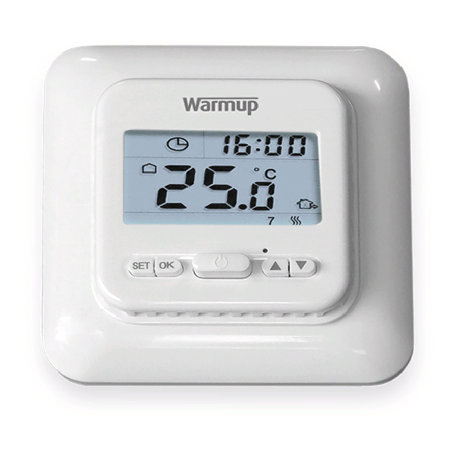
Warmup One - Programmable Thermostat
EN - INSTALLATION INSTRUCTIONS
Technical Specifications
• Model - ONESTAT
• Operating Voltage - 100 - 240 V AC 50/60 Hz
• Max. Load - 16 A (3840 W)
• Dimensions - (H/W/D): 81 x 81 x 25 mm (from wall surface)
• Sensors - Air & Floor
• Sensor Type - 2.5m NTC 100K (can be extended to 50 m)
Safety Information
IMPORTANT INFORMATION: Installation should only be carried out by a qualified and competent electrician. The
Warmup One requires a permanent power supply from a 30mA RCD protected circuit in accordance with the current
edition of the Wiring Regulations. The thermostat and its power supply should be isolated from the mains supply
throughout the installation process. Ensure that wires are fully inserted into the terminals, with no bare wire visible
and secured. Any free strands should be trimmed, as they could otherwise cause a short-circuit.
Step 1 - Identify Suitable Location
Before making any permanent fixtures Warmup recommends identifying your preferred location for the thermostat. It
should be located in an area with good ventilation. It should not be beside a window/door, in direct sunlight or above
another heat generating device (e.g. radiator or TV).
BATHROOM INSTALLATIONS: When installing the thermostat within a bathroom it MUST be mounted outside of Zone 2
in accordance with Wiring Regulations. If it is not possible to identify a suitable location outside of Zone 2 within the
bathroom, then it is recommended that the thermostat is installed in the adjacent room and set to control the heating
by floor temperature only. When installed in this way, it is not possible to directly control the heating based on the
room air temperature, only the floor surface temperature.
Step 2 - Installation and Wiring Connection
Gently press a flat head screwdriver
into the plastic release clips
highlighted above and pull face
outwards, unclipping from the base.
Place the frame and thermostat
face somewhere safe.
Warmup - IM - One - v1.0 2018-07-31.indd 1
• Insulation Class - II
• IP Rating - IP21
• Installation Depth - Min 35mm Pattress
• Compatibility - eUFH
• Er-P Class - I
• Standards - EN60730-1 & EN60730-2-9
Floor Sensor
Heaters
(No Polarity)
(Max. 16 Amps)
1
2
3
4
SENSOR
PE
N1
NTC 100K
Wire as shown above and install to
a 35mm deep (min.) pattress
1 & 2: NTC100K Floor Sensor
(No Polarity)
3: PE - Supply and Load Earth
4: N1 - Load Neutral
5: L1 - Load Live
6: N - Supply Neutral
7: L - Supply Live
5
6
7
L1
L
N
230V AC
Supply
1
31/07/2018 10:58:30
Advertisement
Table of Contents

Related Manuals for Warmup One


Summary of Contents for Warmup One
- Page 1 IMPORTANT INFORMATION: Installation should only be carried out by a qualified and competent electrician. The Warmup One requires a permanent power supply from a 30mA RCD protected circuit in accordance with the current edition of the Wiring Regulations. The thermostat and its power supply should be isolated from the mains supply throughout the installation process.
- Page 2 Remove floor sensor and install a 100K or 10K floor sensor Open Window Function - The Warmup One features open window function which detects when there is a sudden drop in temperature (1.5°C or more within 3 minutes) when a window is opened and will switch your heating off saving you energy.
- Page 3 Back for lunch Period 4 17:30 22°C Leave house after lunch Period 5 17:30 22°C Back home Period 6 22:00 15°C Go to bed. Final period of the day Warmup - IM - One - v1.0 2018-07-31.indd 3 31/07/2018 10:58:31...
- Page 4 (ii) contact Warmup. Warmup will determine whether the product should be returned, or replaced. This warranty does not cover removal or reinstallation costs, and shall not apply if it is shown by Warmup that the defect or malfunction was caused by damage which occurred while the product was in the possession of the end user.
- Page 5 • Standard - EN60730-1 & EN60730-2-9 Säkerhet VIKTIG INFORMATION: Installation får endast utföras av behörig elektriker. Warmup ONE kräver permanent matning enligt branchstandard. Säkerställ att ledare är helt intryckta samt att det inte finns lösa trådar samt att de sitter ordentligt åtdragna.
- Page 6 Installera en 100k eller 10k golvsensor Öppet fönsterfunktion - Warmup ONE har en funktion för att känna av ifall det blir ett plötsligt fall av temperatur (1.5°C eller mer inom 3 minuter) När ett fönster öppnas kommer den att stänga av värmen för att spara energi. Värmen kommer slås på...
- Page 7 Period 3 17:30 22°C Tillbaka för lunch Period 4 17:30 22°C Lämnar huset Period 5 17:30 22°C Hemma för kvällen Period 6 22:00 15°C Sova, återgår sedan till period 1 Warmup - IM - One - v1.0 2018-07-31.indd 7 31/07/2018 10:58:35...
- Page 8 Warmup garanterar att denna produkt är fri från defekter i utförande eller funktion, under normal användning, under en period av 1 år från inköpsdatum. Om produkten på något sätt under garantiperioden är defekt, ska Warmup reparera eller byta ut det.
Need help?
Do you have a question about the One and is the answer not in the manual?
Questions and answers