Table of Contents
Advertisement
Quick Links
Advertisement
Table of Contents

Subscribe to Our Youtube Channel
Summary of Contents for RNA PARU
- Page 1 Operating and Assembly Instruction Linear conveyor PARU...
-
Page 2: Table Of Contents
Table of contents Safety Instrution ........................4 1.1. General information ......................4 1.2. Symbols and notes ......................4 1.3. Intended use ........................4 Product description ........................ 5 2.1. General information ......................5 2.2. Technical data ........................5 2.3. Description of functions ....................7 3. - Page 3 Reichsweg 19-23 52068 Aachen Germany herewith declare under our sole responsibility that with regard to the following product: Machine designation: (function) Linear feeder PARU (…) Type designation: Year: 2019 10865660 0001 – 2500000 0001 Serial number: all relevant essential safety and health requirements of Directive 2006/42/EC have been fulfilled up to the battery li- mits.
-
Page 4: Safety Instrution
These operating and assembly instructions contain all the information required for the safe use and operation of products in the PARU series, namely the models PARU S1 b, S1 u, S1 b wide, S1 u wide, PARU M1 b, M1 u, M1 b wide, M1 u wide, hereinafter referred to as PARU. -
Page 5: Product Description
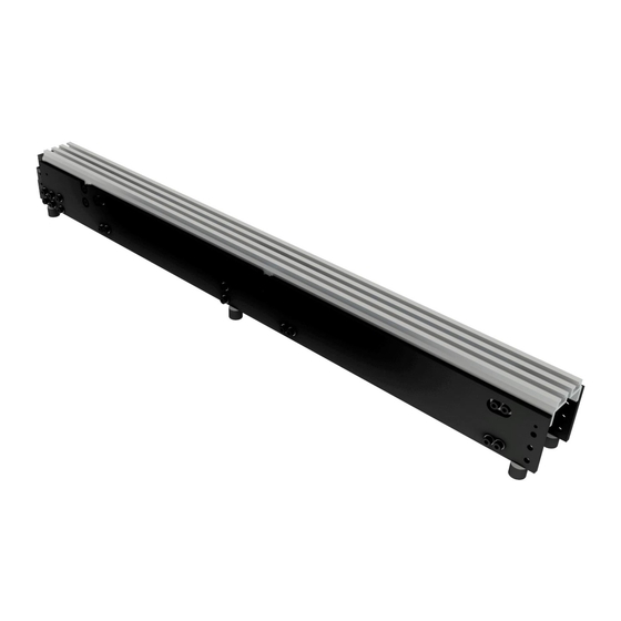
PARU is equipped with a material-specific tooling and integrated into the operator's production or assembly line, either on its own or as part of a feed system. PARU is thus an incomplete machine in the sense of the EC Machinery Directive 2006/42/EC. - Page 6 Figure 1 right illustrates the dimensions of PARU using the example of PARU S1, structure b wide. Figure 2 left illustrates the dimensions of the PARU using the example of PARU S1, structure u. Figure 2 right illus- trates the dimensions of the PARU using the example of PARU S1, structure u wide.
-
Page 7: Description Of Functions
20µm, the amplitude in horizontal direction is up to 80µm. Figures 1 and 2 show PARU without tooling. The tooling is fastened to the effective mass via the grooves of the effective mass by means of M6 nuts. Figure 4 shows a PARU S1, b with an exemplary tooling shown in green. -
Page 8: Mounting Instructions
PARU can be transmitted to the target machine. PARU is screwed to the stand frame provided by the user or to a machine frame of the complete machine via the M6 threaded holes on the underside of the rubber feet. It is recommended that all rubber feet be bolted with ISO4762 M6 bolts of strength 8.8, Loctite threadlocker and a tightening torque of 10Nm. -
Page 9: Operation Instructions
(PE). If necessary, a protective grounding must be carried out on site. The electrical connection of the PARU and the components as well as the commissioning of the PARU may only be carried out by qualified personnel in accordance with the national provisions and regulations of the country in which the PARU is operated. -
Page 10: Tooling Changeover
5. carrying out the rapid emptying and the setup procedure of the upstream feed system, e.g. ROTU, for the complete removal of the old conveyed goods 6. assembly of the new tooling on the PARU. Make sure that the transition to the upstream and downstream process is adjusted accurately. -
Page 11: Storage, Dismantling, Disposal
5. Storage, Dismantling, Disposal The PARU or the toolings must be stored in a dry place and protected from aggressive media or dirt. Strong temperature fluctuations must be avoided. After longer storage periods, cleaning must be carried out in accordance with section 4.3 of these operating and assembly instructions. - Page 12 E-08940 Cornella de Llobregat (Barcelona) Spanien Tel: +34 (0)93 377-7300 Fax.:+34 (0)93 377-6752 E-Mail: info@vibrant-RNA.com www.vibrant-RNA.com www.vibrant.es RNA Digital Solutions in München RNA Digital Solutions GmbH Agnes-Pockels-Bogen 1 80992 München Telefon: +49 (0) 1515 / 99 28 255 E-Mail: kontakt@rnadigital.de www.designforfeeding.com...


Need help?
Do you have a question about the PARU and is the answer not in the manual?
Questions and answers