Table of Contents
Advertisement
Quick Links
Advertisement
Table of Contents

Related Manuals for Soltaro AIO2-INS Series


Summary of Contents for Soltaro AIO2-INS Series
- Page 1 Operating Manual AIO2-INS Series...
- Page 2 Version: DM-AIO2-INS-EN 1.1...
-
Page 3: Table Of Contents
Operating of the Inverter ..............35 Graphical Display ..............35 Commission ................36 Decommission ................37 Settings on the Soltaro APP ............. 38 Troubleshooting ..................45 Technical Data ..................48 Specification of inverter ............48 Specification of battery ............50 Certificates and Grid Regulations .......... -
Page 4: About This Manual
1 About This Manual 1.1 Products Covered by This Manual AIO2-INS Series Low Voltage Solar Hybrid Inverter: AIO2-INS-3000, AIO2-INS-3680, AIO2-INS-4600, AIO2-INS-5000. 1.2 Target Group This document is intended for qualified electrician. Any electrical installation and maintenance on this inverter must be performed by qualified electricians in compliance with standards, wiring rules or requirements of local grid authorities or bodies. -
Page 5: Safety
This manual will be updated if necessary. Please check www.soltaro.com for more information. 2 Safety 2.1 Intended Use The AIO2-INS Series are single phase solar hybrid inverters suitable for both on-grid and off-grid operation. With Lithium batteries, PV panels and a smart meter, the hybrid inverter is the central device to make a solar storage system for increased self-consumption. -
Page 6: Storage And Transportation
Do not touch hot surfaces before it cools down. • Only authorized service personnel are allowed to install • the inverter or perform servicing and maintenance All powers, both AC and DC, should be disconnected • from inverter before attempting any maintenance or cleaning or working on any circuits connected to inverter. -
Page 7: Scope Of Delivery
3 Scope of Delivery Item Designation Inverter Wall Mounting Bracket... - Page 8 Battery power cable(red cable is positive connection, black cable is negative connection) RJ45 Connectors EPS Connector (Amphenol or Wieland) Grid Connector (Phoenix or Wieland) Connectors (Amphenol Multi-Contact MC4) (2PV+,2PV-) WiFi Stick (optional) CT and Smart Meter Terminal Resistor (1kOhm) Smart Meter Communication Connector Screws for Fixing Mounting Bracket BMS Cable Manual...
-
Page 9: Product Description
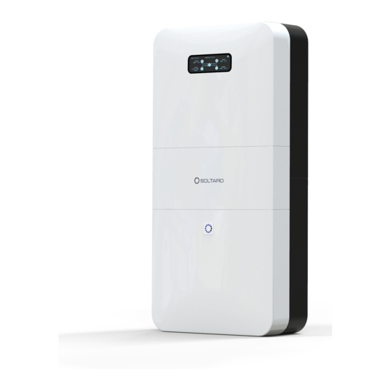
Thank you for choosing the SOLTARO AIO2 ESS product. Features of the inverter are ahead of the field and should be understood prior to install. 4.1 View of the Inverter Figure 1. View of the AIO2-INS Series Hybrid Inverter Position Designation Graphical Display LED light. - Page 10 Symbols on the Type Label Symbol Explanation CE Mark Caution, Risk of Danger Caution, Risk of Electric Shock Caution, Hot Surface. Refer to the Operating Manual Danger, Risk of Electric Shock due to Stored Energy. Cut off all power and wait at least 5 minutes before any work is carried out on the 5min inverter.
-
Page 11: Topology Of The Inverter
4.2 Topology of the Inverter Figure 2. AIO2-INS Series Hybrid Inverter topology 4.3 System Diagram Mobile APP Grid Communication Billing Internet Meter Smart Loads Meter PV Array Router Hyper-S... -
Page 12: Operating Mode Introduction
4.4 Operating Mode Introduction 4.4.1 On Grid Self-Use Operating Mode The on grid self-use operating mode is recommended for when the system is installed in an area with a stable grid. The purpose is to increase self-consumption of clean PV energy. When Inverter is set to work in this mode: During daytime and there is sufficient PV Power, •... - Page 13 • Set a schedule for the inverter to charge the battery using cheap off-peak grid power. • Specify the daily working periods of self-use for inverter. *1: The inverter can be set not to feed power into the grid. But a small amount of energy will still inevitably be fed into grid due to unpredictable PV energy change and load fluctuations.
- Page 14 SOC reaches the EPS restart value. iii. When working in this mode: • The max power*3 from the EPS port is limited by inverter type, battery type and battery SOC. • A larger battery is always recommended for off grid / backup configuration.
-
Page 15: Mounting
5 Mounting 5.1 Requirements for Mounting Check to make sure the installation site does not fall into any of the following conditions: If it does, then a risk assessment will be required. No direct sunlight No rain exposure No snow lay up Direct sunlight Rain exposure Snow lay up... - Page 16 risks. The ambient temperature is outside the range of tolerable • ambient temperature (-20°C to +60°C, -4°F to+140°F). Higher than the altitude of 2,000m above sea level. Above • 2000m the inverter output will be de-rated. Close to flammable materials or areas where flammable •...
-
Page 17: Mounting The Inverter (With Aio2-Btlv-5Kwh Battery)
5.2 Mounting the Inverter (with AIO2-BTLV-5KWH battery) Procedure: STEP 1: Drill holes into the wall (φ=12mm, drilling depth≥ 65mm) The dimensions of the back of the product are as follows (note: the height of the bottom row of holes≥200mm) Unscrew the M8-60 expansion screw and put the expansion head into the drilled hole. - Page 18 STEP 2: Install the hanger with 5 M8-60 inner hexagonal expansion screws, as shown in the picture to the right. STEP 3: Hang the battery on the hanger. Note: Make sure that the four hooks of the hanger are all engaged, otherwise it will not be strong enough.
- Page 19 STEP 5: M8-60 screws marked by the arrows fix the outer frame to the wall. STEP 6: Install the inverter hanger (use 3 M5-10 Phillips head screws to fix the inverter hanger to the frame of the wiring area. The inverter hanger is fixed to the wall with 5 M8-60 screws).
- Page 20 STEP 7: Hang the inverter on the hanger (make sure the four hooks on the side of the rack are engaged, to prevent the inverter from falling). STEP 8: After the battery and inverter are wired, buckle the cover of the wiring area.
-
Page 21: Mounting The Inverter (With Aio2-Btlv-10Kwh Battery)
5.3 Mounting the Inverter (with AIO2-BTLV-10KWH battery) Procedure: STEP 1: Drill holes in the wall (φ=12mm, drilling depth≥ 65mm) The dimensions of the back of the product are as follows (note: the height of the bottom row of holes≥200mm) Unscrew the M8-60 expansion screw and put the expansion head into the drilled hole. - Page 22 STEP 2: Install the hanger with 6 M8-60 inner hexagonal expansion screws, as shown in the picture to the right.
- Page 23 STEP 3: Hang the battery on the hanger. Note: Make sure that the six hooks of the hanger are all engaged, otherwise it will not be strong enough. STEP 4: Install the outer frame of the wiring area. Place the frame of the wiring area on the battery, align the outer frame, and screw three...
- Page 24 STEP 6: Install the inverter hanger (use 3 M5-10 Phillips head screws to fix the inverter hanger to the frame of the wiring area. The inverter hanger is fixed to the wall with 5 M8-60 hex screws). STEP 7: Hang the inverter on the hanger (make sure the four hooks on the side of the rack have been engaged to prevent the inverter from falling).
-
Page 26: Electrical Connection
6 Electrical Connection 6.1 Wiring Diagram Wiring Diagram for Australia & New Zealand In Australia and New Zealand, electrical installation and maintenance shall be conducted by a licensed electrician and shall comply with Australia/New Zealand National Wiring Rules. Because the inverter does not maintain neutral integrity during grid failure, an external neutral connection must be used in Australia and New Zealand. -
Page 27: Wiring Diagram
6.2 Wiring Diagram Wiring Diagram for Europe... -
Page 28: Overview Of The Connection Area
6.3 Overview of the Connection Area Position Designation Grid Connector EPS Output PV Inputs DC Switch (optional) MULTI Port (for Meter & Other Communications) BMS Port DRM Port EMS Port (for WiFi Stick or other EMS Controllers) Battery Connectors Additional Grounding Point 6.4 PV Connection Please only use the PV connectors from the accessory box for connection. - Page 29 • Since the inverter is transformerless, please do not ground either output of the PV panels. Ground the panel frames. • The 3.68kW/4.6KW/5kW inverter is designed with 2 MPPT trackers, if the inputs of the PV panels are paralleled, please consult with your local distributor for technical support.
-
Page 30: Grid Connection
6.5 Grid Connection Please use the Grid connector from the accessory box for connection. Before connecting, please make sure: • The grid voltage and frequency must be in the permissible range. • An external AC switch (≥40A) must be used on the Grid connection to cut the inverter off from the Grid when necessary. -
Page 31: Eps Connection
6.6 EPS Connection If you want to use the energy storage system to power the house (as a standalone system or during Grid failure), the EPS connector should be used and the EPS function should be enabled during setup. Otherwise you can leave the EPS port disconnected. Where possible, an external switch to bypass the inverter to power backup loads directly from the grid must be installed. - Page 32 Declaration for backup loads: Soltaro AIO2-INS inverter is able to supply a continuous 5000VA output (max 5500VA for 10s) on EPS side. Inverter will shut down under full loading with high ambient temperature if grid is absent. Accepted loads as below: •...
-
Page 33: Battery Connection
6.7 Battery Connection 6.7.1 Battery connection diagram 6.7.2 Battery Power Connection Procedure: STEP 1: Please use the pre-assembled • battery power wire in the accessory box for connection. STEP 2: Connect the battery cables to the inverter. A “click” • sound will indicate firm connection. - Page 34 A DC breaker with OCP capability must be installed between inverter and battery. The battery may have this switch integrated. If not, an external DC switch of proper ratings should be used. 6.7.3 BMS Communication Connection Please check whether the BMS communication cable in the accessory box is appropriate for the battery.
-
Page 35: Smart Meter Connection
6.8 Smart Meter Connection Procedure: STEP 1: Normally the smart meter should be placed in or near the • grid distribution box right after the billing meter. STEP 2: Assemble the smart meter connector. Make sure the wires • are correct; please follow the markings on the connector. STEP 3: Please smart... -
Page 36: Wifi Stick Connection
Smart meter type: CHINT DDSU666-D From Grid Smart Meter Cable To Inverter/ Loads 6.9 WiFi Stick Connection Procedure: STEP 1: Insert the WiFi stick to the EMS port and fasten the nut • tight. “EMS” Connector Pin Definition GNDD RS485A RS485B... -
Page 37: Drm Connection
6.10 DRM Connection DRM is provided to support several demand response modes by certain control signals. “DRM” Connector Pin Definition DRM1/5 DRM2/6 DRM3/7 DRM4/8 3.3V DRM0 3.3V... -
Page 38: Operating Of The Inverter
7 Operating of the Inverter 7.1 Graphical Display The graphical display shows the detailed information of the inverter. Position Designation Total energy the inverter has produced. Time and date PV system real-time parameters, including power, voltage and current. If the connection to PV is disconnected, the icon, arrow and data will not be displayed on the screen. -
Page 39: Commission
occurs. 7.2 Commission Before commissioning the inverter, make sure: • The country mark on the box is in accordance with the installation site; • The inverter is correctly and firmly mounted; • The Circuit breaker and RCD are correctly connected and are all in “off”... -
Page 40: Decommission
Please use the Soltaro APP to initiate the self-test procedure • and get the test results. Refer to Soltaro APP Operation Instructions for details. 7.3 Decommission STEP 1: Turn off the load;... -
Page 41: Settings On The Soltaro App
7.4 Settings on the Soltaro APP 7.4.1 User Interface Introduction Inverter List Home Page Inverter Status Overview Grid Status EPS Status Smart Meter Status PV Status SOLTAR O Parameter Display LOCAL BMS Status Energy Today Energy Total System Status Basic Settings... - Page 42 7.4.2 Install the APP and Connect to the Inverter Procedure: STEP 1: Install Soltaro APP Download the app on iOS APP Store and/or Google Play, • and install it on the mobile phone or tablet. STEP 2: Connect to the inverter Connect the mobile phone or pad to the same wireless •...
- Page 43 Turn to Settings interface, click the “Basic Settings”; • Write in the password to enter the setting interface. This • can be accessed by contacting Soltaro. STEP 2: Set the country Check the “Country”, make sure it is your current location; •...
- Page 44 7.4.4 Time Synchronization Procedure: STEP 1: Enter the Setting interface Go to Settings interface, click “Inverter Commands”. • STEP 2: Time Synchronization Click “Time & Date Sync.”. •...
- Page 45 7.4.5 Scheduled Operation (optional) Procedure: STEP 1: Enter the Setting interface Go to Settings interface, click “Scheduled Operation”. • STEP 2: Set the Operation Periods and Parameter Enable the Scheduled Operation; • Set the operation period and parameters, according to •...
- Page 46 7.4.6 Power Quality Response The AIO2-INS Series Hybrid Inverter supports power quality response modes which can be enabled/disabled and setup/adjust via the Soltaro Local APP. Procedure: STEP 1: Enter the Setting interface Go to Settings interface, click “Advanced Settings”. •...
-
Page 48: Troubleshooting
8 Troubleshooting This chapter is a guide for troubleshooting problems that may arise in the installation and operation of AIO2-INS Series inverters. In the event that more than one error is generated at the same time, the hexadecimal error corresponding to each alarm is added together. - Page 49 Error Code Description Solution F1:00100000 Over Heat P1 Wait for the Inverter cools down. Check if the F1:00200000 Over Heat P2 installation place is too hot. F1:00400000 Over Heat P3 F1:00800000 Bat. OTP These errors will reset itself. If it keeps coming and F1:01000000 Bat.
- Page 50 F2:00004000 Firmware incompatible U1/U2 Error Code Description Solution F3:00000001 BMS External Fault Check the battery for parameter settings. Contact F3:00000002 BMS Internal Fault with your local battery’s F3:00000004 BMS OVP distributor. F3:00000008 BMS UVP F3:00000010 BMS Charge OCP Check the battery for parameter settings.
-
Page 51: Technical Data
9 Technical Data 9.1 Specification of inverter Inverter Model AIO2-INS- AIO2-INS- 3680 AIO2-INS- 4600 3000 AIO2-INS- 5000 AC Output @ Grid AC Input Voltage / 186 ~ 264Vac/ 50 or 60Hz Frequency Nominal AC Power 3000W 3680W 4600W/5000W Nominal AC Current 13.0A 16.0A 20A/21.7A... - Page 52 Waveform Pure Sinusoidal Wave THD of AC Voltage <3% with Resistive Load Solar Input Max. allowable PV panel 4500W 5500W 7500W power Max. input power 3300W 4000W 5400W Open circuit voltage 600V MPPT voltage range 125-500 V Max. PV current 12/12A 12/12A Max.
-
Page 53: Specification Of Battery
Max. Efficiency 97.80% Battery Charge Efficiency General Data PV inverter topology Non-isolated 540*430*210 mm(inverter) Dimensions Weight 27kg 29kg 34kg Mounting Information Wall mount -10℃ to +60℃(up 45℃derating) Operating Temperature Relative Humidity 0 to 100%RH Site Altitude Up to 2000m above sea level without derating IP Protection Type IP 65 Protective class... -
Page 54: Certificates And Grid Regulations
General Data Mounting information Wall mount / Ground mount Communication CAN / RS485 Operating Temperature 0~45℃charge / -10~50℃ discharge Dimension 540*430*210 mm 540*680*210 mm Weight 45 kg 85 kg IP Protection Type IP65 9.3 Certificates and Grid Regulations EMC: • EN61000-6-1, EN61000-6-2, EN61000-6-3, EN61000-6-4, EN61000-4-16, EN61000-4-18, EN61000-4-29 Safety:... -
Page 55: Contacts
Contacts: Head Office & Showroom 8 Mohr Street, Tullamarine, VIC, Australia 3043 Tel:+61 1300 276 582 Email: service@soltaro.com Support Head Office service.au@soltaro.com Australian Support UK/Europe Office Unit 8, High Grounds Industrial Est., Worksop, Notts, S80 3AF, United Kingdom Tel:+44 (0)1909 807 577 Email: service.uk@soltaro.com...
Need help?
Do you have a question about the AIO2-INS Series and is the answer not in the manual?
Questions and answers