Table of Contents
Advertisement
Advertisement
Table of Contents

Related Manuals for Soltaro Hyper Series


Summary of Contents for Soltaro Hyper Series
- Page 1 Operating Manual Low Voltage Hyper Series Version: HYPER-LV-1P-AU-1.08...
-
Page 3: Table Of Contents
WiFi Stick Connection ..............25 DRM Connection ..............25 Operating of the Inverter ..............26 LEDs and Graphical Display ...........26 Commission ................28 Decommission ................29 Settings on the Soltaro APP.............30 Troubleshooting ..................38 Technical Data ..................40 Hyper 2000/3000 ..............40 Hyper 3680/4600/5000 .............42 Certificates and Grid Regulations .........44... -
Page 4: About This Manual
1. About This Manual 1.1 Products Covered by This Manual Hyper Series Low Voltage Solar Hybrid Inverter: Hyper 2000, Hyper 3000, Hyper 3680, Hyper 4600, Hyper 5000. 1.2 Target Group This document is intended for qualified electrician. Any electrical installation and maintenance on this inverter must be performed by qualified electricians in compliance with standards, wiring rules or requirements of local grid authorities or bodies. -
Page 5: Safety
This manual will be updated if necessary. Please check www.soltaro.com for more information. 2. Safety 2.1 Intended Use The Hyper Series are single phase solar hybrid inverters suitable for both on-grid and off-grid operation. With Lithium batteries, PV panels and a smart meter, the hybrid inverter is the central device to make a solar storage system for increased self-consumption. - Page 6 the surface may result in burns. Do not touch hot surfaces before it cools down. • Only authorized service personnel are allowed to install the • inverter or perform servicing and maintenance All powers, both AC and DC, should be disconnected from •...
-
Page 7: Scope Of Delivery
3. Scope of Delivery... - Page 8 Item Designation Inverter Wall Mounting Bracket EPS Connector (Amphenol or Wieland) Grid Connector (Phoenix or Wieland) PV Connectors (Amphenol HC4 or Multi- 2 or 4 Contact MC4) WiFi Stick Smart Meter 120 Ohm Resistor Smart Meter Cable Water-proof RJ45 Connector for DRM port Screws for Fixing Mounting Bracket Manual RJ45 Connectors and Communication Cable...
-
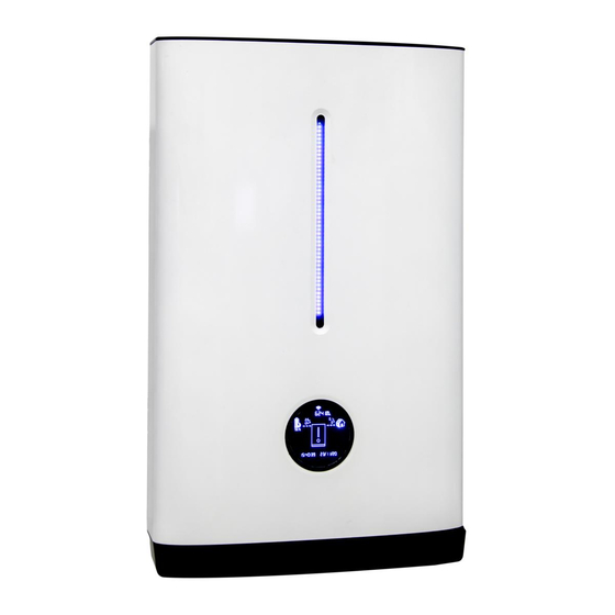
Page 9: Product Description
4. Product Description Thank you for choosing a Soltaro, hybrid solar inverter. Features of the Soltaro inverter are ahead of the field and understood prior to install. 4.1 View of the Inverter Figure 1. View of the Hyper Series Hybrid Inverter... - Page 10 Symbols on the Type Label Symbol Explanation CE Mark Caution, Risk of Danger Caution, Risk of Electric Shock Caution, Hot Surface. Refer to the Operating Manual Danger, Risk of Electric Shock due to Stored Energy. Cut off all power and wait at least 5 minutes before any work is carried out on the inverter.
-
Page 11: System Diagram
4.2 System Diagram Mobile APP Grid Communication Li-ion Billing Internet Battery Meter Smart Hybrid Loads Meter PV Array Router Inverter 4.3 Operating Mode Introduction 4.3.1 On Grid Self-Use Operating Mode The on grid self-use operating mode is recommended for the system installed in area with a stable grid. - Page 12 *2: Firmware update may be required to support this function. For on-grid self-use operating mode, one can set the discharge end SOC@Grid as low as the battery allows (10% or 20% for example). Please refer to your local Soltaro battery technician for minimum discharging end SOC. 4.3.2...
- Page 13 grid at the max allowable current. The battery will not discharge even when SOC reaches 100%. • Local loads will be supported by grid and PV energy. • When grid or diesel generator is not available, When there is enough energy stored in battery, the EPS port •...
-
Page 14: Mounting
5. Mounting 5.1 Requirements for Mounting Check to make sure the installation site does not fall into any of the following conditions: If any do, then a risk assessment will be required. No direct sunlight No rain exposure No snow lay up Direct sunlight Rain exposure Snow lay up... -
Page 15: Mounting The Inverter
chemicals are processed or stored). Exposed to direct sunlight or in an enclosure exposed to • direct sunlight. Little or no air flow • Mounted on a surface without suitable fire/heat rating. • Mounted on a wall without suitable load holding capacity. •... - Page 16 STEP 1: Please use the wall • mounting bracket as template to drill 4 holes on walls. STEP 2: Use expansion bolts • or correct wall fixings attach mounting bracket on the wall tightly. STEP 3: Lift and hang the •...
-
Page 17: Electrical Connection
6. Electrical Connection 6.1 Wiring Diagram Wiring Diagram for Australia & New Zealand Hybrid Inverter Energy Meter Smart Battery Meter N-Bar E-Bar Transfer Switch PV1+ PV1- PV2+ General PV2- Load Load In Australia and New Zealand, electrical installation and maintenance shall be conducted by licensed electrician and shall comply with Australia/New Zealand National Wiring Rules. -
Page 19: Overview Of The Connection Area
6.2 Overview of the Connection Area Multi GRID PV1+ PV2+ B A T T E R Y E M S Position Designation Battery Connectors PV Inputs DC Switch (optional) DRM Port MULTI Port (for Meter & Other Communications) EMS Port (for WiFi Stick or other EMS Controllers) BMS Port EPS Output Grid Connector... -
Page 20: Pv Connection
6.3 PV Connection Please only use the PV connector from the accessory box for connection. Before connecting, please make sure: The voltage, current and power ratings of the panels to be • connected are within the allowable range of the inverter, ensure polarity is correct, please refer to the Technical Data in chapter 9 for voltage and current limits. -
Page 21: Grid Connection
STEP 2: Connect the PV connectors • to the inverter. There should be a “click” to indicate firm connection. 6.4 Grid Connection Please use the Grid connector from the accessory box for connection. Before connecting, please make sure: The grid voltage and frequency must be in the permissible •... - Page 22 STEP 3: Connect additional • grounding wire to the heatsink and fasten the screw. High leakage current! Earth connection essential before connecting supply. •...
-
Page 23: Eps Connection
6.5 EPS Connection If you want to use the energy storage system to power the house (as a standalone system or during Grid failure), the EPS connector should be used and the EPS function should be enabled in setup. Otherwise you could leave the EPS port un-connected. Before connecting, please make sure: The grid voltage and frequency must be in the permissible •... -
Page 24: Battery Connection
6.6 Battery Connection Battery connection diagram DRM MULTI PV1 - PV1 + E MS B+ B- PV2 - PV Switc h G RID PV2 + Breaker Battery Power 6.6.1 Battery Power Connection Procedure: STEP 1: Please use the pre-assembled • battery power wire in the accessory box for connection. - Page 25 switch integrated. If not, an external DC switch of proper ratings should be used. 6.6.2 BMS Communication Connection Please check whether the BMS communication cable in the accessory box is appropriate for the battery. If you are not sure for that, please confirm with your battery vendor. Procedure: STEP 1: Please...
-
Page 26: Smart Meter Connection
6.7 Smart Meter Connection Procedure: STEP 1: Normally the smart meter should be placed in or near the • grid distribution box right after the billing meter. STEP 2: Please use the smart meter cable • accessory communication. Insert the RJ45 connector with water-proof cap into the port marked “MULTI”... -
Page 27: Wifi Stick Connection
6.8 WiFi Stick Connection Procedure: STEP 1: Peel off the tape that covers the • EMS port. STEP 2: Insert the WiFi stick to the EMS • port and fasten the two screws tight. 6.9 DRM Connection DRM is provided to support several demand response modes by certain control signals. -
Page 28: Operating Of The Inverter
7. Operating of the Inverter 7.1 LEDs and Graphical Display The LEDs indicate the operating state of the inverter and also battery SOC. Status Explanation Green LED Glowing The inverter has been powered up. Red LED Glowing An Error has occurred. Full Length SOC >... - Page 29 Position Designation EMS port communication status. Total energy the inverter has produced. Battery parameters, voltage and current are displayed alternatively. Direction of the battery energy. BMS Status. if this label is not shown, BMS Connections should be checked. SOC of the Battery. PV panels parameters, voltage and current are displayed alternatively.
-
Page 30: Commission
7.2 Commission Before commissioning the inverter, make sure: The country mark on the box is in accordance with the • installation site; The inverter is correctly and firmly mounted; • The Circuit breaker and RCD are correctly connected and • are all in “off”... -
Page 31: Decommission
Please use the Soltaro APP to initiate the self-test • procedure and get the test results. Refer to Soltaro APP Operation Instructions for details. 7.3 Decommission STEP 1: Turn off the load; STEP 2: Turn off the PV;... -
Page 32: Settings On The Soltaro App
7.4 Settings on the Soltaro APP 7.4.1 User Interface Introduction Inverter List Home Page Inverter S tatus Overview Grid Status EP S S tatus S mart Meter S tatus P V S tatus P roPower APP P arameter Display BMS S tatus... - Page 33 7.4.2 Install the APP and Connect to the Inverter Procedure: STEP 1: Install Soltaro APP Download the app on iOS APP Store and/or Google Play, • and install it on the mobile phone or pad. STEP 2: Connect to the inverter Connect the mobile phone or pad to the same wireless •...
- Page 34 7.4.3 Check the Country Procedure: STEP 1: Enter the Setting interface Turn to Settings interface, click the “Basic Settings”; • Write in the password, to enter the setting interface. • STEP 2: Set the country Check the “Country”, make sure it is your current location; •...
- Page 35 7.4.4 Time Synchronization Procedure: STEP 1: Enter the Setting interface Turn to Settings interface, click the “Inverter Commands”. • STEP 2: Time Synchronization Click the “Time & Date Sync.”. •...
- Page 36 Click the “Battery BMS”; • Write in the number of paralleled batteries; • Click “Apply”, to save the settings. • This setting is only available for SOLTARO batteries. The parallel connection of other batteries should follow instructions of corresponding battery vendors.
- Page 37 7.4.6 Scheduled Operation (optional) Procedure: STEP 1: Enter the Setting interface Turn to Settings interface, click the “Schedule Operation”. • STEP 2: Set the Operation Periods and Parameter Enable the Scheduled Operation; • Set the daily/weekly mode, according to your situation; •...
- Page 38 7.4.7 Other Settings (optional) One may do the following settings, according to the situations and/or local regulations. Settings other than the following, may also be available, but should under suggestions assistance distributors/manufacturer. Procedure: STEP 1: Enter the Setting interface Turn to Settings interface, click the “Basic Settings”. •...
-
Page 40: Troubleshooting
8. Troubleshooting This chapter is a guide for troubleshooting problems that may arise in the installation and operation of hyper series inverters. In the event that more than one error is generated at the same time, the hexadecimal error corresponding to each alarm are added together. - Page 41 F2:00000004 Insulation Fault Check the insulation of PV panels. F2:00000008 RCMU Fault Check the PV Panels. F2:00000010 Grid Relay Fault These errors will reset itself. If it keeps coming and finally the F2:00000020 EPS Relay Fault Inverter is latched up, please F2:00000040 Bypass Relay Fault contact...
-
Page 42: Technical Data
9. Technical Data 9.1 Hyper 2000/3000 PV Inputs Hyper 2000 Hyper 3000 Max. PV-generator power 2500W 3300W Max. PV voltage 550V d.c. Rated PV Voltage 360V d.c. MPPT Voltage Range 125~500V d.c. PV Start Voltage 100V d.c. Max. PV current 12A d.c. - Page 43 Battery Ratings Hyper 2000 Hyper 3000 Battery Type Lithium Rated Battery Voltage 48V d.c. Battery Voltage Range 40~60V d.c. Max. Charge Current 40A d.c. 60A d.c. Max. Discharge Current 40A d.c. 60A d.c. PS Max. (per CEI 0-21) 1900W 2800W PC Max.
-
Page 44: Hyper 3680/4600/5000
9.2 Hyper 3680/4600/5000 PV Inputs Hyper 3680 Hyper 4600 Hyper 5000 Max. PV-generator power 4000VA 5400VA 5400VA Max. PV voltage 550V d.c. Rated PV Voltage 360V d.c. MPPT Voltage Range 125~500V d.c. PV Start Voltage 100V d.c. Max. PV current 10A/10A d.c. - Page 45 Max. Charge Current 60A d.c. 100A d.c. 100A d.c. Max. Discharge Current 60A d.c. 100A d.c. 100A d.c. PS Max. (per CEI 0-21) 2800W 4600W 4700W PC Max. (per CEI 0-21) 3600W 4600W 5000W Galvanic Isolation for Battery Communication Interfaces CAN/RS485 Efficiencies Hyper 3680...
-
Page 46: Certificates And Grid Regulations
9.3 Certificates and Grid Regulations EMC: • EN61000-6-1, EN61000-6-2, EN61000-6-3, EN61000-6-4, EN61000-4- 16, EN61000-4-18, EN61000-4-29 Safety: • IEC/EN62109-1 & -2, IEC62040-1 Grid Regulations: • G83/2, G59/3; AS/NZS4777.2; C10/11; CEI 0-21; RD1699; C 15-712-1; VDE-AR-N 4105; EN50438/NL; EN50438/IE. -
Page 47: Contacts
Contacts: Head Office Level 9, 440 Collins Street, Melbourne, Australia 3043 +61 1300 276 582 UK Office Unit 8, High Grounds Industrial Est., Worksop, Nottinghamshire, S80 3AF, United Kingdom +44 (0)1909 807 577 China Office No. 200 Linghu Road, Wuxi 214100, China Europe Office Porta Piazzetta, 2 GR-6537, San Vittore –...
Need help?
Do you have a question about the Hyper Series and is the answer not in the manual?
Questions and answers