Advertisement
Quick Links
Parts
INSTRUCTIONS-PARTS LIST
INSTRUCTIONS
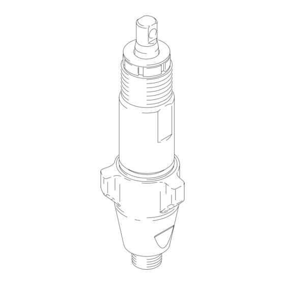
Displacement Pump
3600 psi (250 bar, 24.8 MPa) Maximum Working Pressure
Model 239923, Series A
Used in the Ultra Max and Ultimate Mx 795 and 1095 Sprayers
Used in the GMax and GMx 3900 Sprayers
Model 240291, Series A
Used in the Ultra Max and Ultimate Mx 1595 Sprayers
Used in the GMax and GMx 5900 Sprayers
Used in the GMax 10000 Sprayers
Model 240917, Series A
Used in the GMax and GMx 7900 Sprayers
Model 240800, Series A
Used in the GMax 5900HD and Mark V Sprayers
Model 243344, Series A
Used in the LineLazer II 3900 Sprayers
Model 243345, Series A
Used in the LineLazer II 5900 Sprayers
This manual contains important
warnings and information.
READ AND KEEP FOR REFERENCE.
GRACO INC. P.O. BOX 1441 MINNEAPOLIS, MN 55440–1441
ECOPYRIGHT 1997, GRACO INC.
Graco Inc. is registered to I.S. EN ISO 9001
308798
Rev. W
8016A
Advertisement

Related Manuals for Graco 240291


Summary of Contents for Graco 240291
- Page 1 Used in the LineLazer II 3900 Sprayers Model 243345, Series A Used in the LineLazer II 5900 Sprayers 8016A GRACO INC. P.O. BOX 1441 MINNEAPOLIS, MN 55440–1441 ECOPYRIGHT 1997, GRACO INC. Graco Inc. is registered to I.S. EN ISO 9001...
- Page 2 D This equipment is for professional use only. D Read all instruction manuals, tags, and labels before operating the equipment. D Use the equipment only for its intended purpose. If you are uncertain about usage, call your Graco distributor. D Do not alter or modify this equipment. Use only genuine Graco parts and accessories.
- Page 3 If the sleeve cannot be 239923 244196 removed easily, return the sleeve and cylinder to 240291 244198 your Graco distributor for removal. 240917 240916 240800 244198 243344 244196 2. Remove and clean the sleeve when you are...
- Page 4 Service Repair When Pump Is Off The Sprayer Disassembling the pump Fig. 3. Disassemble intake valve. Clean and inspect. O-ring (227) may require a pick for removal. Fig. 1. Remove packing nut (202) and throat adjust- ment spacer (228). 7570A Fig.
- Page 5 COMPONENT RUPTURE HAZARD Do not clean or wipe the piston valve threads. Cleaning the piston valve threads could destroy the special sealing Used on 240291 patch and cause the piston valve to come loose 240800 during operation, causing pump bursting and &...
- Page 6 Torque to 27 +/–3 ft-lb (239923) Fig. 13. Install seal (201) into packing nut (202). Install Torque to 55 +/–3 ft-lb throat adjustment spacer onto packing nut. Loosely (240291, 240800) install packing nut into cylinder. Torque to 55 +/–5 ft-lb (240917) 7581A 7576A Fig.
- Page 7 Service Fig. 14. Grease piston packings and sleeve top edge. Fig. 16. Grease top inch or two of piston rod that will go through the cylinder throat packings. 7579A Fig. 16 Fig. 17. Grease o-ring (221) and place on sleeve. Slide sleeve/piston rod assembly into bottom of cylinder.
- Page 8 Fig. 19. Install intake valve on cylinder. If a wrench is used torque as follows: 5 ft-lb (for model 239923) +/– 5 ft–lb (for models 240291 & 240800) +/– 5 ft–lb (for model 240917). +/– If a wrench is not used, be sure intake valve is bot- 7568A tomed out against cylinder.
- Page 9 Notes 308798...
- Page 10 Service Repair When Pump Is On The Sprayer Fig. 2. Use screwdriver to push retaining spring up and WARNING push pin out. INJECTION HAZARD To reduce the risk of serious injury, whenever you are instructed to relieve pressure, follow the Pressure Relief Procedure on page 3.
- Page 11 Service Fig. 4. Remove piston rod and sleeve. Fig. 7. Invert piston rod and insert into cylinder to force out throat packings. 7746A Fig. 4 Fig. 4. Invert piston rod and sleeve and pound on hard surface until piston rod comes out of sleeve. 7747A Fig.
- Page 12 Stack male gland (204). Alternately stack UHMWPE (203) and leather (223) packings (note orientation). Install female gland (224). Install seal (201) and packing nut (202) and throat adjustment spacer (228). Used on 240291, 240917 & 240800 7748A Fig. 9 7573B 7581A Fig.
- Page 13 Install piston valve on piston rod. Torque as follows: 3 ft-lb (for model 239923) +/– 3 ft-lb (for model 240291 & 240800) +/– 5 ft-lb (for model 240217) +/– 7577A Fig.
- Page 14 Fig. 19. Use screwdriver to push retaining spring up. Fig. 22. Install intake valve on cylinder. Wrench torque as follows: 5 ft-lb (for model 239923) +/– 5 ft-lb (for model 240291 & 240800) +/– 5 ft-lb (for model 240917) +/– Note: Make sure retaining ring falls into slot.
- Page 15 Service Cross Sectional Reference Pump 240291 & 240917 V-Maxt UHWMPE, blue Leather Pump 240291 & 240917 V-Maxt UHWMPE, blue Leather 7683B Fig 23 Technical Data Maximum working pressure ..... . .
- Page 16 Parts – Pumps 239923 and 243344 Model 239923, Series A Carbon Steel Displacement Pump 221* Part No. Description Qty. 224* 179810 SEAL, throat 193046 NUT, packing 203* 192692 V-PACKING, throat, V-Maxt UHMWPE, blue *223 204* 178942 GLAND, male, throat 219* 203* CYLINDER, pump 240522...
- Page 17 Parts – Pumps 240291 and 243345 Model 240291, Series A Carbon Steel Displacement Pump 221* Part No. Description Qty. 224* 183171 PLUG *203 193032 NUT, packing 203* 193124 V-PACKING V-Maxt UHMWPE, blue 219* 223* 204* 183176 GLAND, packing, male, throat...
- Page 18 Parts – Pump 240917 221* Model 240917, Series A Carbon Steel Displacement Pump Part No. Description Qty. 219* 112590 PLUG 189589 NUT, packing 203* 193722 V-PACKING V-Maxt UHMWPE, blue 240920 CYLINDER, pump 224* *218 203* 206* 107203 BALL, sst, 0.5625 in. *203 207* 107306...
- Page 19 Parts – Pump 240800 Model 240800, Series A Carbon Steel Displacement Pump 221* Part No. Description Qty. 183171 PLUG 224* 193032 NUT, packing 203* 193124 V-PACKING V-Maxt UHMWPE, blue *203 204* 183176 GLAND, packing, male, throat 241334 CYLINDER, pump 219* 223* 206* 101947...
- Page 20 Graco’s written recommendations. This warranty does not cover, and Graco shall not be liable for general wear and tear, or any malfunction, damage or wear caused by faulty installation, misapplication, abrasion, corrosion, inadequate or improper maintenance, negligence, accident, tampering, or sub- stitution of non–Graco component parts.
Need help?
Do you have a question about the 240291 and is the answer not in the manual?
Questions and answers