
Related Manuals for JUMO dTRANS O2 01


Summary of Contents for JUMO dTRANS O2 01
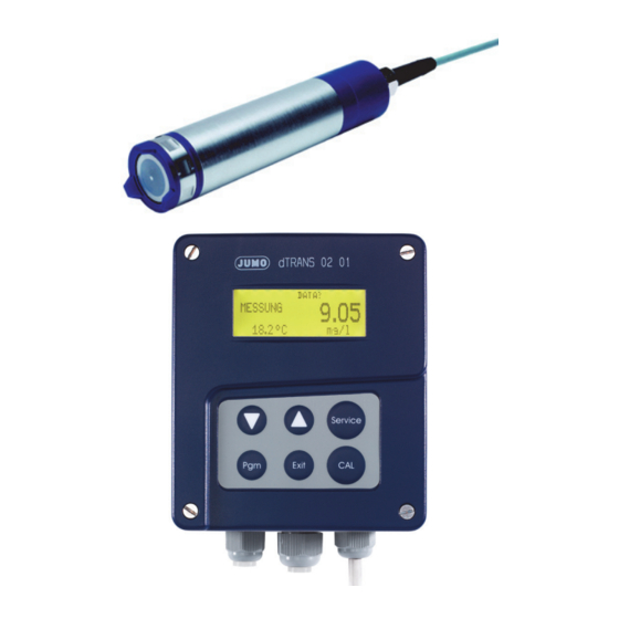
- Page 1 Type 202610.0 Two-wire Transmitter for dissolved oxygen (DO) terminal box/ operating unit B 20.2610.0 Operating Instructions 12.05/00394433...
-
Page 3: Table Of Contents
Typographical conventions ............5 Warning signs ....................5 Note signs ....................5 General ..................6 Preface ......................6 Arrangement of the oxygen measuring system ...........7 Oxygen transmitter dTRANS O2 01 ........11 Application ....................11 Construction ....................11 Function .....................12 Influence .....................12 Instrument identification ............14 Nameplate ....................14... - Page 4 Contents Standard version (operating unit) ............34 Maximum version (operating unit with own PSU) .........36 Setup program ................ 39 Function .....................39 Commissioning ............... 40 Starting up ....................40 Calibration ................42 10.1 General .......................42 10.2 Calibrating ....................42 Operation ................. 45 11.1 Function .....................45 11.2 Display in measurement mode ..............46 11.3...
-
Page 5: Typographical Conventions
1 Typographical conventions Warning signs Danger This symbol is used when there may be danger to personnel if the instructions are ignored or not followed correctly! Caution This symbol is used when there may be damage to equipment or data if the instructions are ignored or not followed correctly! Note signs Note... -
Page 6: General
2 General Preface Please read these Operating Instructions before commissioning the instrument. Keep the manual in a place that is accessible to all users at all times. Please assist us to improve these operating instructions, where necessary. Your suggestions will be appreciated. Phone +49 661 6003-0 +49 661 6003-607 All necessary settings are described in this manual. -
Page 7: Arrangement Of The Oxygen Measuring System
The basic version is designed for direct connection to a PLC or a recorder. The calibration function can be initiated locally. An optional setup program is available for configuring the transmitter. The two-wire transmitter is powered by a separate power supply (optional), e.g. JUMO TN-22, see Data Sheet 95.6024... - Page 8 2 General Basic version, type 202610/80... The JUMO dTRANS Az 01 (Jumo Data Sheet 20.2550), bezel size 96 x 48 is a suitable indicator/controller for the basic version. This instrument is recommended where there is no requirement for a direct connection to a PLC or recorder.
- Page 9 The two-wire transmitter and the operating unit are powered by a separate power supply (optional), e.g. JUMO TN-22, see Data Sheet 95.6024. A further power supply (e.g. JUMO TN-22) is required for the supply of the additional (optional) two-wire transmitter for temperature.
- Page 10 2 General Full (maximum) version, type 202610/82... Operating unit (Maximum version) Supply 110 — 240 V 20 — 30 V AC/DC signal output for oxygen (4 — 20 mA) SERVICE - PLC - Visualization 2 relay outputs EXIT - or similar signal output for temperature (4 —...
-
Page 11: Oxygen Transmitter Dtrans O2 01
3 Oxygen transmitter dTRANS O2 01 Application General The instrument is suitable for continuous measurement of dissolved oxygen in water. Typical areas of - Measurement of the O content in activation basins. The measurement application signal is used here for monitoring, and as a control parameter. -
Page 12: Function
3 Oxygen transmitter dTRANS O2 01 The cathode, with which the oxygen diffused through the membrane reacts electrochemically, is in direct contact with the membrane, via a thin electrolyte film. Function of the The transmitter operates on the 2-wire principle, i.e. the output is a transmitter proportional modulation (4 —... - Page 13 - or the present atmospheric pressure is measured and entered on the transmitter. The dTRANS O2 01 offers both entry options. The entries are made through the setup program, or on the operating unit. Salinity Salinity denotes the content of dissolved salts in water (in weight %).
-
Page 14: Instrument Identification
M.K. JUCHHEIM GmbH&Co GmbH&Co Fulda Germany Fulda Germany www.jumo.net www.jumo.net JUMO dTRANS O2 01 (Bedieneinheit) JUMO dTRANS O2 01 Typ: 202610/80-500-2000-08-28 Typ: 202610/80-500-2000-08-28 F - Nr.:12345678 00 0 0051 0004 F - Nr.:12345678 00 0 0051 0004 DC 19...31V DC 19...31V... -
Page 15: Instrument Description
5 Instrument description Technical data of the two-wire transmitter Supply 19 — 31 V DC; nominal 24 V DC; 8 VA Permissible -5 to 50°C ambient temperature Length of the connecting cable Electrical screw terminals connection Lightning coarse and fine protection protection Electromagne- to EN 61 326... -
Page 16: Technical Data For The Terminal Box / Operating Unit
5 Instrument description Burden Type 82 Type 81 Type 80 (maximum version) (basic version) (standard version) dissolved oxygen/temp. dissolved oxygen dissolved oxygen/temp. 350 Ohm – 17 V – 11 V 0.02 A 0.02 A Response time oxygen measurement (at 25°C): t <... -
Page 17: Assembly
6 Assembly Two-wire transmitter Installation The transmitter type 202610 has a G1 A (1" pipe) thread (1) (underneath the variations blue cap) and can be screwed into suitable immersion or flow-through fittings. Operating Preferably vertical, with the membrane (2) pointing down. position Alternative transmitter positions are allowed under unfavorable flow conditions, but not beyond the horizontal position. -
Page 18: Flow-Through Fittings
6 Assembly Flow-through fittings Application Flow-through fittings are used to accommodate the dTRANS O2 01 oxygen transmitter. The fittings are installed directly in the pipeline conveying the liquid, or in the bypass. The special construction of the fitting ensures a correct flow past the sensor, thereby avoiding measurement errors. - Page 19 6 Assembly Flow-through Material: housing PVC fitting, hose pipe clip PP connection Permissible temperature: +5 to +50°C Safe pressure: up to 1 bar Connection: G1/4 (1/4" pipe) for 8 x 6 mm hose dia. Sales No. 20/00398142...
-
Page 20: Immersion Fittings
6 Assembly Immersion fittings Application Immersion fittings are used to accommodate the dTRANS O2 01 oxygen transmitter. The fittings are installed in open containers or sluices using the pipe clips supplied. Different immersion depths are facilitated by various immersion lengths. - Page 21 6 Assembly...
-
Page 22: Suspension Fittings
6 Assembly Suspension fittings Application Suspension fittings are used to accommodate the dTRANS O2 01 oxygen transmitter. The fittings are primarily employed for measurement in open basins. The fitting can be positioned far from the edge of the basin, suspended from a chain by the shackle, for example. Different immersion depths are facilitated by various immersion lengths. - Page 23 6 Assembly...
-
Page 24: Float Fittings
Application Float fittings are used to accommodate the immersion fitting in which the dTRANS O2 01 oxygen transmitter is installed. The fittings are primarily used for measurement in open basins or waterbodies. Different immersion depths are facilitated by various immersion lengths of the fitting. - Page 25 6 Assembly Float fitting Material: Permissible temperature: +5 to +50°C Fitting mounting: 40 mm Sales No. 20/00397483 Suitable Immersion length: 500 mm immersion Sales No. 20/00398131 fitting Immersion length: 1500 mm Sales No. 20/00398135 Fitting (sliding) Immersion fitting with two-wire transmitter for dissolved oxygen Float...
-
Page 26: Support Column With Pedastal Base, Arm, Chain And Weather Protection Canopy
Application This accessory is intended for installation at the edge of a basin. The dTRANS O2 01 oxygen transmitter is installed in a suspension fitting. Different immersion depths and distances from the edge of the basin are facilitated by the arm and the chain. - Page 27 6 Assembly Terminal box Weather protection canopy or operating unit Pipe mounting assembly Universal joint (adjustable) with clamping lever approx. 1500 Chain Arm (adjustable) Suspended fitting for Support column two-wire transmitter for dissolved oxygen Pedestal base Support column or Weather protection canopy vertical pipeline Operating unit...
-
Page 28: Terminal Box / Operating Unit
6 Assembly Terminal box / operating unit ✱ Make sure that the site is readily accessible, for calibration at a later time. Installation site ✱ The fixing must be secure and free from vibration. ✱ Avoid direct sunlight. Drilling A drilling template is included in these operating instructions (last page), to template mark out for wall mounting without fixing brackets . - Page 29 6 Assembly Pipe mounting (option) Using the pipe mounting assembly, the terminal box / operating unit (and, if required, the weather protection canopy) can be mounted on pipes or railings with diameters from 30 to 50 mm. Panel mounting For panel mounting, only the the top of the housing is installed. ✱...
-
Page 30: Installation
7 Installation The electrical connection must only be carried out by qualified personnel! ❏ The choice of cable, the installation and the electrical connection must conform to the requirements of VDE 0100 “Regulations on the Installation of Power Circuits with Nominal Voltages below 1000 V” or the appropriate local regulations. -
Page 31: General
7 Installation General ➩ "Panel mounting”, page 29. Opening the terminal box / operating unit To connect the single conductors, pull off the pluggable screw terminals (1) in the terminal box / operating unit. Feed the connection cables through the Pg glands (2). Basic version (terminal box) Connection diagram... - Page 32 7 Installation Terminal Color Terminal in terminal box Signal assignment of the two-wire Pink transmitter Green Yellow White b Pt1000 Brown a Pt1000 +e / -I Blue -e / -I Screen Gray start CAL Terminal Connection Screw terminals assignment of the terminal Supply 10 L+ 19 —...
- Page 33 7 Installation Connection Outside area Control room Supply voltage 24 V DC 1...8 10 / 12 14 / 15 Setup – PLC Terminal box – – Indicator – Controller Input 4 — 20 mA (dissolved oxygen) Supply 24 V DC Two-wire transmitter for (optional) dissolved oxygen...
-
Page 34: Standard Version (Operating Unit)
7 Installation Standard version (operating unit) Connection diagram (10) O2 e-l (11) (12) (13) (14) Temp. E-l (15) Terminal Color Terminal in operating unit Signal assignment of the two-wire Pink transmitter Green Yellow White b Pt1000 Brown a Pt1000 +e / -I Blue -e / -I Screen... - Page 35 7 Installation Connection Screw terminals Input (from two-wire transmitter for dissolved oxygen) Output (dissolved oxygen) 10 L+ 4 — 20 mA 2-wire 12 L- Proportional 4 — 20 mA current in supply Output (measurement point temperature) Proportional 4 — 20 mA current in supply Connection Outside area...
-
Page 36: Maximum Version (Operating Unit With Own Psu)
7 Installation Maximum version (operating unit with own PSU) Connection diagram Supply Contact 1 common make Contact 2 common make (10) O2 e-l (11) (12) (13) Temp. e-l (14) (15) Terminal Color Terminal in operating unit Signal assignment of the two-wire Pink transmitter Green... - Page 37 7 Installation Connection Screw terminals Input (from two-wire transmitter for dissolved oxygen) Output (dissolved oxygen) 10 L- 4 — 20 mA 2-wire 11 L+ The current loop must always be closed; either by means of a recording instrument or similar, or a jumper between the terminals 10 and 11.
- Page 38 7 Installation Connection (stand alone) Outside area Control room 1...8 10 / 11 14 / 13 Setup Jumper L1 / N Operating unit Two-wire transmitter for dissolved oxygen Supply...
-
Page 39: Setup Program
9 V battery as a power source. Supply 24 V DC for the two-wire transmitter 2-wire connection JUMO dTRANS O2 01 signal output for oxygen (4 — 20 mA) - PLC - Visualization - or similar. Plug-on adapter... -
Page 40: Commissioning
9 Commissioning Starting up The transmitter has been tested in the factory for fault-free functioning and is delivered ready for operation. The membrane (3) must not be touched or made dirty! In the course of normal operation, a grayish-white deposit may form on the anode of the sensor module. - Page 41 9 Commissioning Oxygen cells must be "run in" before calibration. This means that the cell is connected to the transmitter and then continuously operated in air that is saturated with water vapor until the reading no longer changes. Note: The vapor-saturated air is several centimeters above the water surface.
-
Page 42: Calibration
10 Calibration 10.1 General When to - during commissioning calibrate? - when the sensor module is replaced - after lengthy breaks in operation without supply voltage Application- - drinking water: 1 to 6 months specific - monitoring of waterbodies calibration (river or lakes): 1 to 4 months cycles... - Page 43 10 Calibration Calibrating The membrane must not be damaged! The measurement signal may change during calibration! Control devices or PLCs operated by the transmitter may react in an undesirable manner! The output signal will be set to the value (normally 18 mA) that has been defined as the service current. ✱...
- Page 44 10 Calibration Calibration If no stable value is produced within 15 minutes after pressing the key, the unsuccessful two-wire transmitter for dissolved oxygen will remain in the service mode. The output current will remain at the value defined as the service current (factory- set to 18 mA).
-
Page 45: Operation
11 Operation 11.1 Function Front view of basic version CAL key, to start calibration Front view of standard / maximum version PGM key LC display Confirm entries / step on with parameters EXIT key SERVICE key cancel entry without saving; call up service function cancel calibration DOWN key... -
Page 46: Display In Measurement Mode
11 Operation 11.2 Display in measurement mode K1 K2 ALARM SETUP SERVICE Measurement 10.25 mg/l 18.5°C Status display of configured contacts K1 and K2. If the characters are visible, the corresponding contact is activated. Indicates present alarm states (e.g. calibration alarm, measurement out-of-range). -
Page 47: Principle Of Operation
11 Operation 11.3 Principle of operation Operation within levels Measurement mode > 2 s EXIT Configuration level time-out (25 s approx.) EXIT Parameter level Time-out (25 s approx.) 11.4 Configuration level Operation INPUT TEMPERATURE INPUT ANALOG OUTPUT RELAY 1 Additional parameters that can Arrow pointing up;... - Page 48 11 Operation Settings at the configuration Measurement mode level > 2 s EXIT ➩ Page 50 INPUT EXIT ➩ Page 51 TEMPERATURE INPUT EXIT ➩ Page 52 ANALOG OUTPUT EXIT ➩ Page 53 RELAY 1 EXIT ➩ Page 54 RELAY 2 EXIT ➩...
-
Page 49: Parameter Level
11 Operation 11.5 Parameter level Operation O INPUT UNIT mg/l The parameter that was selected at the configuration level The parameter that can be altered at the parameter level. Step on to the next parameter with Selection option between different settings or alterations of values using the UP or DOWN key. - Page 50 11 Operation Settings at the parameter level Configuration level INPUT Selection / Standard INPUT value range EXIT UNIT mg/l or % mg/l time-out EXIT PRESSURE COMPENS. ATMOSPHERIC ATMOSP. PRESSURE or PRESS- HEIGHT a.m.s.l. time-out ATMOSPH. PRESS. or EXIT HEIGHT AMSL 500 —...
- Page 51 11 Operation Settings at the parameter level Configuration level TEMPERATURE Selection / Standard TEMPERATURE INPUT INPUT value range °C or °F °C EXIT TEMPERATURE UNIT time-out EXIT -5.0 to 5.0 °C TEMPERATURE OFFSET time-out EXIT 0.0 — 100.0 FILTER TIME [SEC] time-out AUTOMATIC or...
- Page 52 11 Operation Settings at the parameter level Configuration level ANALOG Selection / Standard ANALOG OUTPUT OUTPUT Value range EXIT SCALING 4 mA -199.9 — 199.9 0.0 mg/l time-out EXIT SCALING 20 mA -199.9 — 199.9 20.0 mg/l time-out EXIT 3.6 or 22.0 mA 22.0 ON OVERRANGE time-out...
- Page 53 11 Operation Settings at the parameter level Configuration level RELAY 1 or RELAY 1 or RELAY 2 Selection / Standard RELAY 2 value range EXIT LIMIT VALUE -199.9 — 199.9 0.0 time-out EXIT HYSTERESIS 0.01 — 99.9 0.01 time-out EXIT PULL-IN DELAY 0.0 —...
- Page 54 11 Operation Settings at the parameter level Configuration level SERVICE Selection / Standard SERVICE value range EXIT ANALOG OUTPUT [mA] 3.6 — 21.0 18.0 time-out EXIT K1 WITH SERVICE ACTIVE or ACTIVE INACTIVE time-out EXIT K2 WITH SERVICE ACTIVE or ACTIVE INACTIVE time-out...
- Page 55 11 Operation Settings at the parameter level Configuration level OPERATION Selection / Standard OPERATION value range EXIT CODE 0 — 999.9 time-out EXIT ACTIVE or INACTIVE CODE FUNCTION INACTIVE time-out ALWAYS ON On the EXIT LCD LIGHTING basic and ALWAYS OFF standard IN OPERATION versions:...
-
Page 56: Special Functions
11 Operation 11.6 Special functions Time-out If no key is pressed for about 25 sec, the transmitter jumps back to the measurement mode. Exception: During the “SERVICE function” and “Calibration” procedures, the time-out function is not active. SERVICE This function can be used to prevent undefined reactions in connected systems while inspecting or cleaning the transmitter or sensor. - Page 57 11 Operation Activating the Point of departure is the measurement mode. CODE function ✱ Press the key for more than 2 seconds (start configuration) ✱ Step on to the configuration item OPERATION by repeatedly pressing the DOWN key. ✱ Select the OPERATION configuration item using the key.
-
Page 58: Maintenance
12 Maintenance 12.1 Two-wire transmitter for dissolved oxygen Do not touch the membrane or the (optional) protective film with sharp or pointed objects! Do not damage the membrane or the (optional) protective film! The measurement signal may change during maintenance work! Control devices or PLCs operated by the transmitter may react in an undesirable manner! General... -
Page 59: Replacing The Sensor Module
12 Maintenance 12.2 Replacing the sensor module The maximum theoretical life of the sensor module with air saturation and at 20°C is 5 years. A grayish-white deposit may form on the anode of the sensor module. This deposit does not affect the functioning of the measuring cell. - Page 60 12 Maintenance Installation ✱ Insert sensor module (3) into transmitter (5), keeping it straight. Make sure that the seal (4) is seated correctly. ✱ Screw on union nut (2) finger tight. ✱ Screw on protection basket (1) (1/3 cw turn to the notch).
-
Page 61: Eliminating Faults And Malfunctions
13 Eliminating faults and malfunctions Fault / malfunction Possible cause Elimination Precautionary measures No reading No supply Check supply voltage. ➩ "Installation”, page No sensor reaction 30ff. Check electrical connection. ➩ "Installation”, page 30ff. Jumper is missing. Check electrical connection. ➩... - Page 62 13 Eliminating faults and malfunctions Fault / malfunction Possible cause Elimination Precautionary measures Indicated value too Clean cell membrane ➩ "Cleaning”, page 58 and / or: wait for stable output signal, then recalibrate. ➩ "Calibration”, page 42ff. ➩ Chapter 5.1 No flow Check flow and restore, if necessary.
- Page 63 13 Eliminating faults and malfunctions Fault / malfunction Possible cause Elimination Precautionary measures When measuring in The run-in time was Extend the run-in time, Select a run-in time areas of low oxygen too short. then recalibrate. that is sufficiently long. concentration: The electrolyte in the Only calibrate when...
-
Page 64: Appendix
14 Appendix 14.1 Before configuration If a number of instrument parameters have to be modified in the instrument, then it is advisable to note them in the table below, and then modify these parameters in the sequence given. The following list shows the maximum number of parameters that can be altered. - Page 65 14 Appendix Parameter Selection / value range Factory see page setting setting NONE x > w O FUNCTION K1 or x < w O NONE FUNCTION K2 x > w TEMP x < w TEMP K1or K2 ACTIVE or INACTIVE ACTIVE ON OVERRANGE CONTACT TYPE K1or K2...
-
Page 67: Drilling Diagram
15 Drilling diagram 100.5 Note: 1. Fix template to appropriate surface. 2. Drill holes ( 4.5 mm and 10 mm dia. as marked). Ø Ø 3. Use a piercing saw or similar tool to cut out the template along the inside of the marked line. 4.
Need help?
Do you have a question about the dTRANS O2 01 and is the answer not in the manual?
Questions and answers