Table of Contents
Advertisement
Quick Links
USER MANUAL
Series X G2 - Maritime Multi Computer (MMC) Models
HD 19T22 MxC-yyy-yyyyyy - 19.0 inch Maritime Multi Computer
HD 24T22 MxC-yyy-yyyyyy - 24.0 inch Maritime Multi Computer
HD 26T22 MxC-yyy-yyyyyy - 25.54 inch Maritime Multi Computer
HD 27T22 MxC-yyy-yyyyyy - 27.0 inch Maritime Multi Computer
(where x is either; M=Standard (MMC), E=ECDIS Calibrated (MEC)
Please visit www.hattelandtechnology.com for the latest electronic version of this manual.
(where y=configurations/factory options)
User Manual MMC Series X G2
Updated: 07 Jul 2021
Doc Id: INB101191-1 (Rev 11)
Created: 363
Approved: 6987
Advertisement
Table of Contents

Related Manuals for EMBRON Hatteland X G2 Series


Summary of Contents for EMBRON Hatteland X G2 Series
- Page 1 USER MANUAL Series X G2 - Maritime Multi Computer (MMC) Models HD 19T22 MxC-yyy-yyyyyy - 19.0 inch Maritime Multi Computer HD 24T22 MxC-yyy-yyyyyy - 24.0 inch Maritime Multi Computer HD 26T22 MxC-yyy-yyyyyy - 25.54 inch Maritime Multi Computer HD 27T22 MxC-yyy-yyyyyy - 27.0 inch Maritime Multi Computer (where x is either;...
- Page 2 Copyright © 2021 Hatteland Technology AS Eikeskogvegen 52, N-5570 Aksdal, Norway. All rights are reserved by Hatteland Technology AS. This information may not, in whole or in part, be copied, photocopied, reproduced, translated or reduced to any electronic medium or machine- readable form without the prior written consent of Hatteland Technology AS.
-
Page 3: Table Of Contents
Contents Contents ..................3 Contents of package ....................... 8 General ..................11 IEC62368 policy - Introduction ..................... 12 About this manual ......................... 13 About Hatteland Technology ....................13 www.hattelandtechnology.com ..................... 13 Contact Information ......................13 Maritime Multi Computer (MMC) Generation 2 (G2) - Introduction ........14 Product Labeling ........................ - Page 4 Contents Specifications ................47 Specifications - HD 19T22 MxC-xxx-xxxxxx ................. 48 Specifications - HD 24T22 MxC-xxx-xxxxxx ................. 49 Specifications - HD 26T22 MxC-xxx-xxxxxx ................. 50 Specifications - HD 27T22 MxC-xxx-xxxxxx ................. 51 Specifications - CAN Module with CO-Processor ..............52 ZIA0001310-B ........................
- Page 5 Contents Technical Drawings - HD VED SX2-H1 ................87 VESA Adapter 24, 26, 27 inch ................... 87 Technical Drawings - HD VED SX2-I1 .................. 88 VESA Adapter 24 inch ....................... 88 Technical Drawings - HD VED SX2-J1 ................. 89 VESA Adapter 26 inch ....................... 89 Technical Drawings - HD VED SX2-K1 ................
- Page 6 Contents Appendixes ..................111 SSD Selection Guide ......................112 BIOS Default Settings Overview ..................116 Pinout Assignments ......................123 IEC62368 policy for Hatteland Technology products ............126 Basic Trouble-shooting ....................... 128 Trouble-shooting ......................... 129 Operating System Recovery (tool) ..................129 How to activate Windows Recovery Environment on OS Drive ........133 Declaration of Conformity ....................
- Page 7 This page left intentionally blank...
-
Page 8: Contents Of Package
Contents of package Note: Entries listed below are for Standard factory shipments. Customized factory shipments may deviate from this list. Item Description Illustration 1 pcs of power cable European Type F “Schuko” to IEC. EUR TYPE F Length 1.8m TP52/TC01-1,8M 1 pcs of power cable US Type B plug to IEC. - Page 9 Package may also include: (based on accessories/options ordered) Item Description Illustration Depending on factory mounted options, Terminal Bracket Connector kit as follows: 4 x 5-pin Terminal Block 3.81 for RS-422 / RS-485 NMEA COM (PCA200828-1 / PCA100293-1) 4 x 4-pin Terminal Block 3.81 for CAN Interface (ZIA0001310-B) 4 x 5-pin Terminal Block 3.81 for Digital Input/Output (PCA100297-1) Note: Location of module(s) may 2 x 5-pin Terminal Block 3.81 for RS-422 / RS-485 NMEA COM + Digital Input/Output (Q170 IO)
- Page 10 This page left intentionally blank...
-
Page 11: General
General... -
Page 12: Iec62368 Policy - Introduction
IEC62368 policy - Introduction Safety Instructions Please read and understand the material in the manual in its entirety before doing any installation/servicing/upgrades. Personnel who are allowed to do work on the unit is detailed in the “IEC62368 policy for Hatteland Technology product”... -
Page 13: About This Manual
Hatteland Technology AS About this manual The manual contains electrical, mechanical and input/output signal specifications. All specifications in this manual, due to manufacturing, new revisions and approvals, are subject to change without notice. However, the last updated and revision date of this manual are shown both on the frontpage and also in the “Revision History” chapter. This user manual is a standard/general manual that applies to all variations of its product family, i.e. -
Page 14: Maritime Multi Computer (Mmc) Generation 2 (G2) - Introduction
Panel Computers Series X Generation 2 (G2) Maritime Multi Computer (MMC) Generation 2 (G2) - Introduction Integrating powerful Intel Skylake/Kaby Lake processor-based computers, high quality display technology and advanced video processing, Hatteland Technology’s second generation Series X Panel Computers are the most powerful all-in-one computer/display solution available for maritime technology manufacturers and systems integrators available today. -
Page 15: Product Labeling
Product Labeling Introduction This section details the locations, content details and specifications for factory mounted labels for all currently available standard Hatteland Technology Panel Computer (MMC) models. This information will in most cases also apply for most Customized Models as well, but may differ based on customer requirements, in that case, please refer to the customized User Manual (paper or electronic version, dependent on customer requirements). - Page 16 Product Labeling Label Locations Number ID and coloring based on “Label Size and Types“ table from previous page. All illustrations below are seen from rear (and side where needed) with connectors facing down. Actual labels regarding its size and text orientation vs product size is drawn in.
- Page 17 Product Labeling Warranty Label If you are to perform service on a unit still under warranty, any warranty will be void if this label show signs of removal attempts or damaged by screw driver. This label is located on the back of the product and covers a key screw. This is to aid service departments in determining if there has been any unauthorized service on a unit still under warranty.
-
Page 18: Touch Screen Products
Touch screen products Introduction to products with touch screen Nearly all of our products with touch screen use Projected Capacitive Touch screen (PCTS), widely used with great success on mobile phones and typical pad devices. PCTS can be equally effective also for marine applications. One of the advantages of PCTS is that it has features seen in both resistive and surface capacitive touch screen technologies. - Page 19 Touch Screen Products Touch Screen Drivers All units with Touch Screens are automatically detected by the Operating System via HID. There is no need to install additional Third-Party touch screen drivers. Microsoft® Windows® Svr Emb Std 2012 / Microsoft® Windows® 7 / Microsoft® Windows® 10 IoT: - Please use Windows®...
- Page 20 Touch Screen Products Touch Screen Calibration If you experience any deviation in the touch input accuracy, consider re-calibrating the touch screen for your system. Procedures below are for standard Microsoft® Windows® Operating System calibrate functions. Example for Microsoft® Windows® 10 IoT: 1.Open Control Panel.
-
Page 21: Installation
Installation... -
Page 22: General Installation Recommendations
General Installation Recommendations First Things First! CORRECT HANDLING! CORRECT HANDLING! IND100148-5 - Rev 05 ATTENTION! To prevent damage to chassis and glass, please review the illustrations ! Place horizontally on a smooth and clean surface (table with cloth) Do not stress the corners, nor p RRECT HANDLING! RRECT HANDLING! WRONG HANDLING! -
Page 23: Installation Limitations
General Installation Recommendations 8. Information about necessary pull-relievers for cables is indicated in the Physical Connection section of this manual. Attention must be paid to this information so that cable breaks will not occur, e.g. during service work. 9. Do not paint the product. The surface treatment influences the excess heat transfer. Painting, labels or other surface treatments that differ from the factory default, might cause overheating. - Page 24 General Installation Recommendations General mounting instructions 1. The useful life of the components of all Electronics Units generally decreases with increasing ambient temperature; it is therefore advisable to install such units in air-conditioned rooms. If there are no such facilities these rooms must at least be dry, adequately ventilated and kept at a suitable temperature in order to prevent the formation of condensation inside the display unit.
-
Page 25: Ergonomics
General Installation Recommendations Ergonomics 1. The front surface of the display glass has an anti-reflective (AR) coating which can be scratched and damaged with improper cleaning. It is recommended using only 90+% pure Isopropyl alcohol (Isopropanol) and a soft fabric cloth for this first cleaning. -
Page 26: Cables
General Installation Recommendations Cables Use only high quality shielded signal cables. Cable Entries & Connectors (Marked area) Illustration below for smallest/largest sizes only. Bottom View - Displays Back View - Displays Bottom View - Panel Computers Back View - Panel Computers Maximum Cable Length Any cable should generally be kept as short as possible to provide a high quality input/output. -
Page 27: Housing / Terminal Block Connector Overview
General Installation Recommendations Housing / Terminal Block Connector Overview Housing / Terminal Block connectors are available in different sizes (example 2-pin, 4-pin, 5-pin) which plug into the connector area of the unit. They are mounted by factory default and delivered with the unit. The housing / terminal block connectors have steering rails, which ensures that it can not be mounted wrong. - Page 28 General Installation Recommendations Configuring Housing / Terminal Block connectors Below is a brief illustration that might be useful during configuration and installation of such connectors. You will need suitable pre-configured cable(s) and tools to configure the connector(s) and cable(s) that are present in your installation environment.
-
Page 29: Panel Cutout / Console Mounting Bracket Kit For 19 Inch
Installation Procedures Panel Cutout / Console Mounting Bracket Kit for 19 inch You need: Hex tool (5mm), 1 pcs of HD CMB SX2-N1 Kit (included in delivery). Attention: A suitable pre-cut panel cutout should be made prior to mounting. Do not force the unit into the panel cutout as it might break the outer glass or scratch the chassis on the unit. - Page 30 Installation Procedures ▼ 5: Mount the Thumb Screw and Mounting Socket Nut ▼ 6: Finally, in a even way fasten each of the 4 Thumb through each of the flat brackets threaded holes as Screws to securly fasten the unit to the rear of the Panel illustrated and fasten the Mounting Nut tight at the end.
-
Page 31: Panel Cutout / Console Mounting Bracket Kit For 24 And 27 Inch
Installation Procedures Panel Cutout / Console Mounting Bracket Kit for 24 and 27 inch You need: Torx T25 tool, 1 pcs of HD CMB SX2-E1 kit (included in delivery). Procedure suitable for: Display and Panel Computers Series X Generation 2 range. Brackets are EN60945 Tested. Attention: A suitable pre-cut panel cutout should be made prior to mounting. -
Page 32: Panel Cutout / Console Mounting Bracket Kit For 26 Inch
Installation Procedures Panel Cutout / Console Mounting Bracket Kit for 26 inch You need: Torx T25 tool, 1 pcs of HD CMB SX2-F1 kit (included in delivery). Procedure suitable for: Display and Panel Computers Series X Generation 2 range. Brackets are EN60945 Tested. Attention: A suitable pre-cut panel cutout should be made prior to mounting. -
Page 33: Mounting Bracket, Table / Desktop / Ceiling - 15, 17 And 19 Inch
Installation Procedures Mounting Bracket, Table / Desktop / Ceiling - 15, 17 and 19 inch Procedure suitable for: Display (MMD) and Panel Computer (MMC) Series X Generation 2 (G2) product ranges. 19 inch Maritime Multi Display (MMD) used as example below. You need: - M3 Unbrako®... - Page 34 Installation Procedures ▼ 5: Please note the Factory Mounted Torx screws on both bracket sides, THESE ARE NOT TO BE ADJUSTED OR LOOSENED! ▼ 6: Fasten the complete unit to your table/desktop location, and tilt it into the desired position. Locate the Set Socket Screws on both brackets decribed in step 3.
-
Page 35: Mounting Bracket, Table / Desktop / Ceiling - 24, 26 And 27 Inch
Installation Procedures Mounting Bracket, Table / Desktop / Ceiling - 24, 26 and 27 inch You need: M5 Unbrako® Hex Key tool and 1 pcs of HD TMB SX1-C1 Mounting Bracket Kit. Fasteners (6 pcs M6) for Table / Desktop location not included. Procedure suitable for: Display and Panel Computers. 24 inch unit used as illustration below, but same procedure apply for 26 and 27 inch units as well. - Page 36 Installation Procedures ▼ 5: You may now mount the unit onto your desired location. It is advised that you unlock the Lock Pin (as shown in step 4), tilt the unit 90° backwards (FIG1) and properly fasten the bracket base into location (FIG2). NB! Be careful not to break or scratch the edge of the front glass! Then repeat step 4 again until your desired tilting position has been achieved and you have verified that the Lock Pin are in locking position and the unit is firmly attached and does not appear loose (FIG3).
-
Page 37: Physical Connections
Physical Connections Connection area of 24, 26 and 27 inch units (illustration) Grounding Screw Module(s) Grounding Screw Module(s) Grounding Screw Module(s) Grounding Screw Power Expansion Area for 1 x DisplayPort Out 1 x RJ45 Network (2) 1 x RJ45 Network (3) Power Inputs DC &... - Page 38 Physical Connections GROUNDING SCREWS: Several Grounding Screws are available on unit. Depending on factory installed modules, choose any of the nearby Grounding Screws located near modules (Expansion) area. See references in illustration above. Please review “General mounting instructions” in the “Installation” chapter, pt. 7 for more information. Note for Grounding Screws:Standard Grounding Screw/Bolt provided by Hatteland Technology is “Pan head screws M4x8mm w/spring and plainwasher”.
- Page 39 Physical Connections 2 x 2.5” Removable SATA SSD/HDD Trays (Factory Option): If ordered as factory option, the unit can utilize 2 x Storage Devices (SSD), 2.5” size. (1 x tray is by factory default occupied if Operating System was factory installed at Device #0). The storage devices can be easily be upgraded or replaced by loosening the thumbscrew on each side and pulling the tray out.
- Page 40 Physical Connections EXPANSION AREA for Optional modules: In this expansion area of the unit (1 x small and 2 x large), optional factory mounted modules may be available if ordered. (see illustrations below or dedicated Data Sheets as well as “Housing / Terminal Block Connector Overview” in this manual for more information).
-
Page 41: Com Ports Numbering
Physical Connections Internal (COM port) support for remote controlling MMC units: A detailed description of the SCOM (Serial/Ethernet Communication) can be found here: https://www.hattelandtechnology.com/hubfs/pdfget/inb100018-5.htm - Review also the “Pinout Assignments” chapter in this manual for additional help during preperation and/or installation of external equipment intended to communicate with. - Page 42 This page left intentionally blank...
-
Page 43: Operation
Operation... -
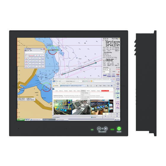
Page 44: User Controls
User Controls USER CONTROLS OVERVIEW The units are designed using Glass Display Control™ (GDC) touch technology to allow interactivity adjusting brilliance (brightness) and control power on / off with the use of illuminated symbols. Note that these symbols are only visible (backlight illuminated) when suitable power is connected. - Page 45 User Controls ECDIS Status / Indicator: (optional factory standard) For units that have been factory ECDIS calibrated the text “ECDIS” will illuminate in green constantly as long as the unit is powered. The “+” and “-” symbols will illuminate in orange when the Brightness/Brillance is adjusted either above or below ECDIS factory calibration point.
- Page 46 This page left intentionally blank...
-
Page 47: Specifications
Specifications... -
Page 48: Specifications - Hd 19T22 Mxc-Xxx-Xxxxxx
Specifications - HD 19T22 MxC-xxx-xxxxxx SPECIFICATIONS Note: All specifi cations are subject to change without prior notice! Please visit www.hattelandtechnology.com for the latest electronic version. All specifications are subject to change without prior notice! TFT Technology: Physical Considerations: • High Quality TFT with LED Backlight Technology •... -
Page 49: Specifications - Hd 24T22 Mxc-Xxx-Xxxxxx
Specifications - HD 24T22 MxC-xxx-xxxxxx SPECIFICATIONS Note: All specifi cations are subject to change without prior notice! Please visit www.hattelandtechnology.com for the latest electronic version. All specifications are subject to change without prior notice! TFT Technology: Physical Considerations: • LED Backlight Technology, TFT Active-matrix •... -
Page 50: Specifications - Hd 26T22 Mxc-Xxx-Xxxxxx
Specifications - HD 26T22 MxC-xxx-xxxxxx SPECIFICATIONS Note: All specifi cations are subject to change without prior notice! Please visit www.hattelandtechnology.com for the latest electronic version. All specifications are subject to change without prior notice! TFT Technology: Physical Considerations: • LED Backlight Technology, TFT Active-matrix •... -
Page 51: Specifications - Hd 27T22 Mxc-Xxx-Xxxxxx
Specifications - HD 27T22 MxC-xxx-xxxxxx SPECIFICATIONS Note: All specifi cations are subject to change without prior notice! Please visit www.hattelandtechnology.com for the latest electronic version. All specifications are subject to change without prior notice! TFT Technology: Physical Considerations: • LED Backlight Technology, Color Active Matrix •... -
Page 52: Specifications - Can Module With Co-Processor
Specifications - CAN Module with CO-Processor All specifications are subject to change without prior notice! This information may not, in whole or in part, be copied, photocopied, DATASHEET reproduced, translated or reduced to any electronic medium or machine- readable form without the prior written consent of Hatteland Technology AS. -
Page 53: Specifications - Nmea / Iec Com Module Rs-422 / Rs-485
Specifications - NMEA / IEC COM Module RS-422 / RS-485 This information may not, in whole or in part, be copied, photocopied, DATASHEET reproduced, translated or reduced to any electronic medium or machine- readable form without the prior written consent of Hatteland Technology AS. - Page 54 Specifications - NMEA / IEC COM Module RS-422 / RS-485 SPECIFICATIONS Note: All specifi cations are subject to change without prior notice! Please visit www.hattelandtechnology.com for the latest electronic version. CAUTION This unit contains electrostatic sensitive devices. Observe precautions for handling. Users who needs to open the unit set jumper settings will VOID THE WARRANTY! Before opening, proper ESD measurements must be taken! 1.
- Page 55 Specifications - NMEA / IEC COM Module RS-422 / RS-485 SPECIFICATIONS Note: All specifi cations are subject to change without prior notice! Please visit www.hattelandtechnology.com for the latest electronic version. 5-pin Isolated NMEA COM COM Ports are identifed in the Operating System “RS-422/RS-485”...
- Page 56 Specifications - NMEA / IEC COM Module RS-422 / RS-485 SPECIFICATIONS Note: All specifi cations are subject to change without prior notice! Please visit www.hattelandtechnology.com for the latest electronic version. NMEA Standards: IEC61162-1 chapter 3.5.5 state that the input shall withstand 15V between ground and input. The reference speed specified is set at 4800 bit/s.
-
Page 57: Specifications - Isolated Digital Input/Output Module
Specifications - Isolated Digital Input/Output Module All specifications are subject to change without prior notice! This information may not, in whole or in part, be copied, photocopied, DATASHEET reproduced, translated or reduced to any electronic medium or machine- readable form without the prior written consent of Hatteland Technology AS. - Page 58 Pin 13 SELECT Signal from printer to indicate that the printer is selected. Pin 14 AUTO FEED This active low output causes the printer to add a line feed after each line Pin 15 ERR# Signal from printer indicating that an error has been detected. Pin 16 INIT# This active low output initialises (resets) the printer.
-
Page 59: Specifications - Lan Module
Specifications - LAN Module All specifications are subject to change without prior notice! This information may not, in whole or in part, be copied, photocopied, DATASHEET reproduced, translated or reduced to any electronic medium or machine- readable form without the prior written consent of Hatteland Technology AS. -
Page 60: Specifications - Isolated Com Module Rs-232
Specifications - Isolated COM Module RS-232 All specifications are subject to change without prior notice! Pinout Assignments This information may not, in whole or in part, be copied, photocopied, DATASHEET reproduced, translated or reduced to any electronic medium or machine- Serial COM RS-232 non-isolated, 9-pin DSUB Female Serial COM RS-485/RS-422, 9-pin DSUB Male readable form without the prior written consent of Hatteland Technology... -
Page 61: Specifications - Nmea / Iec Com + Digital Io Module
Specifications - NMEA / IEC COM + Digital IO Module All specifications are subject to change without prior notice! This information may not, in whole or in part, be copied, photocopied, DATASHEET reproduced, translated or reduced to any electronic medium or machine- readable form without the prior written consent of Hatteland Technology AS. - Page 62 Specifications - NMEA / IEC COM + Digital IO Module All specifications are subject to change without prior notice! SPECIFICATIONS Note: All specifi cations are subject to change without prior notice! Please visit www.hattelandtechnology.com for the latest electronic version. Additional Note: RS-422 / RS-485, NMEA / IEC COM 5-pin Isolated NMEA COM COM Ports are identifed in the Operating System “RS-422/RS-485”...
- Page 63 Specifications - NMEA / IEC COM + Digital IO Module All specifications are subject to change without prior notice! SPECIFICATIONS Note: All specifi cations are subject to change without prior notice! Please visit www.hattelandtechnology.com for the latest electronic version. Additional Note: RS-422 / RS-485, NMEA / IEC COM NMEA Standards: IEC61162-1 chapter 3.5.5 state that the input shall withstand 15V between ground and input.
- Page 64 This page left intentionally blank...
-
Page 65: Specifications Accessories
Specifications Accessories... -
Page 66: Specifications - Jh C01Mf A-A
Specifications - JH C01MF A-A This information may not, in whole or in part, be copied, photocopied, DATASHEET reproduced, translated or reduced to any electronic medium or machine- readable form without the prior written consent of Hatteland Technology AS. The products may not be copied or duplicated in any way. Hatteland Technology AS Manufacturer: ACCESSORY... -
Page 67: Specifications - External Modules (Usb)
Specifications - External Modules (USB) Specifications - External Modules (USB) All specifications are subject to change without prior notice! This information may not, in whole or in part, be copied, photocopied, DATASHEET reproduced, translated or reduced to any electronic medium or machine- readable form without the prior written consent of Hatteland Technology AS. - Page 68 Specifications - External Modules (USB) All specifications are subject to change without prior notice! SPECIFICATIONS Note: All specifi cations are subject to change without prior notice! Please visit www.hattelandtechnology.com for the latest electronic version. Ordering Details: TypeNumber Description Internal Specifications (link to separate datasheets) HT 00262 OPT-A1 NMEA COM (Based on PCA200828-1) 4 x NMEA RS-422/RS-485 isolated...
-
Page 69: Technical Drawings
Technical Drawings... -
Page 70: Technical Drawings - Hd 19T22 Mxc-Xxx-Xxxxxx
Technical Drawings - HD 19T22 MxC-xxx-xxxxxx IND100132-366... -
Page 71: Technical Drawings - Hd 24T22 Mxc-Xxx-Xxxxxx
Technical Drawings - HD 24T22 MxC-xxx-xxxxxx IND100132-329... -
Page 72: Technical Drawings - Hd 26T22 Mxc-Xxx-Xxxxxx
Technical Drawings - HD 26T22 MxC-xxx-xxxxxx IND100132-330... -
Page 73: Technical Drawings - Hd 27T22 Mxc-Xxx-Xxxxxx
Technical Drawings - HD 27T22 MxC-xxx-xxxxxx IND100132-331... - Page 74 This page left intentionally blank...
-
Page 75: Technical Drawings - Accessories
Technical Drawings - Accessories... -
Page 76: Technical Drawings - Hd Cmb Sx2-N1
Technical Drawings - HD CMB SX2-N1 Console Mount Kit 19 inch IND100132-427... -
Page 77: Technical Drawings - Hd Cmb Sx2-E1
Technical Drawings - HD CMB SX2-E1 Console Mount Kit 24 inch IND100132-323... -
Page 78: Console Mounting 24 Inch
Technical Drawings - HD CMB SX2-E1 Console Mounting 24 inch IND100132-323... -
Page 79: P006801-1 Flush Mounting 24 Inch
Technical Drawings - HD CMB SX2-E1 P006801-1 Flush Mounting 24 inch IND100132-323... -
Page 80: Technical Drawings - Hd Cmb Sx2-F1
Technical Drawings - HD CMB SX2-F1 Console Mount Kit 26 inch IND100132-322... -
Page 81: Console Mounting 26 Inch
Technical Drawings - HD CMB SX2-F1 Console Mounting 26 inch IND100132-322... -
Page 82: P007084-1 Flush Mounting 26 Inch
Technical Drawings - HD CMB SX2-F1 P007084-1 Flush Mounting 26 inch IND100132-322... -
Page 83: Technical Drawings - Hd Cmb Sx2-E1
Technical Drawings - HD CMB SX2-E1 Console Mount Kit 27 inch IND100132-324... -
Page 84: Console Mounting 27 Inch
Technical Drawings - HD CMB SX2-E1 Console Mounting 27 inch IND100132-324... -
Page 85: P020721 - Flush Mounting 27 Inch
Technical Drawings - HD CMB SX2-E1 P020721 - Flush Mounting 27 inch IND100132-324... -
Page 86: Technical Drawings - Hd Ved Sx2-C1
Technical Drawings - HD VED SX2-C1 VESA Adapter 19 inch IND100132-318... -
Page 87: Technical Drawings - Hd Ved Sx2-H1
Technical Drawings - HD VED SX2-H1 VESA Adapter 24, 26, 27 inch IND100132-345... -
Page 88: Technical Drawings - Hd Ved Sx2-I1
Technical Drawings - HD VED SX2-I1 VESA Adapter 24 inch IND100132-384... -
Page 89: Technical Drawings - Hd Ved Sx2-J1
Technical Drawings - HD VED SX2-J1 VESA Adapter 26 inch IND100132-385... -
Page 90: Technical Drawings - Hd Ved Sx2-K1
Technical Drawings - HD VED SX2-K1 VESA Adapter 27 inch IND100132-386... -
Page 91: Technical Drawings - Jh 19Tap Std-C1
Technical Drawings - JH 19TAP STD-C1 19 inch Series X to fit 19 inch Series 1 Console Cutout IND100132-273... -
Page 92: Technical Drawings - Hd 19Tap Sx2-C2
Technical Drawings - HD 19TAP SX2-C2 19 inch Series X to fit 19 inch Series 2 Console Cutout IND100132-340... - Page 93 Technical Drawings - HD 19TAP SX2-C2 19 inch Series X to fit 19 inch Series 2 Console Cutout IND100132-340...
-
Page 94: Technical Drawings - Jh 26Tap Std-A1
Technical Drawings - JH 26TAP STD-A1 26 inch Series X to fit 26 inch Series 1 Console Cutout IND100132-275... -
Page 95: Technical Drawings - Hd 26Tap Sx1-A1
Technical Drawings - HD 26TAP SX1-A1 26 inch Series X to fit 27 inch Series 1 Console Cutout IND100132-389... -
Page 96: Technical Drawings - Hd Tmb Sx2-A1
Technical Drawings - HD TMB SX2-A1 Desktop/Table Mounting Bracket 19 inch IND100132-368... -
Page 97: Technical Drawings - Hd Tmb Sx1-C1
Technical Drawings - HD TMB SX1-C1 Desktop/Table Mounting Bracket 24/26/27 inch IND100132-265... -
Page 98: Desktop/Table Mounting Bracket 24 Inch
Technical Drawings - HD TMB SX1-C1 Desktop/Table Mounting Bracket 24 inch IND100132-265... -
Page 99: Desktop/Table Mounting Bracket 26 Inch
Technical Drawings - HD TMB SX1-C1 Desktop/Table Mounting Bracket 26 inch IND100132-265... -
Page 100: Technical Drawings - Hd 19Cov Sx1-A1
Technical Drawings - HD 19COV SX1-A1 UV Sun Cover (19 inch) IND100132-297... -
Page 101: Technical Drawings - Hd 24Cov Sx1-A1
Technical Drawings - HD 24COV SX1-A1 UV Sun Cover (24 inch) IND100132-298... -
Page 102: Technical Drawings - Hd 26Cov Sx1-A1
Technical Drawings - HD 26COV SX1-A1 UV Sun Cover (26 inch) IND100132-342... -
Page 103: Technical Drawings - Hd 27Cov Sx1-A1
Technical Drawings - HD 27COV SX1-A1 UV Sun Cover (27 inch) IND100132-343... -
Page 104: Technical Drawings - Hd Cak Sx2-A1
Technical Drawings - HD CAK SX2-A1 Front Console Mounting/Adapter Kit (24 inch) IND100132-401... -
Page 105: Technical Drawings - Hd Cak Sx2-B1
Technical Drawings - HD CAK SX2-B1 Front Console Mounting/Adapter Kit (27 inch) IND100132-402... -
Page 106: Technical Drawings - P007131-1
Technical Drawings - P007131-1 IP66 Panel Gasket (19 inch) IND100132-333... -
Page 107: Technical Drawings - P022211
Technical Drawings - P022211 IP66 Panel Gasket (24 inch) IND100132-432... -
Page 108: Technical Drawings - P007178
Technical Drawings - P007178 IP66 Panel Gasket (26 inch) IND100132-332... -
Page 109: Technical Drawings - P018743
Technical Drawings - P018743 IP66 Panel Gasket (27 inch) IND100132-292... -
Page 110: Technical Drawings - External Modules (Usb)
Technical Drawings - External Modules (USB) IND100132-245... -
Page 111: Appendixes
Appendixes... -
Page 112: Ssd Selection Guide
SSD Selection Guide Solid State Disk (SSD) Devices Last revised : November 2020 SSD's has many benefits over conventional hard drives where operational performance in marine environment is the reason for Hatteland Technology to recommend SSD's. Historically, the limited write endurance and storage capability vs cost been the main limitations for SSD devices. - Page 113 SSD Selection Guide Calculation / estimation of operational lifetime Assumed System with Hatteland Technology provided SSD or selected according to guide above. 1. Measure/estimate/calculate average disk usage per day. For measuring, use SMART data. Measure the difference in numbers of write cycles at the start and at end of the test (or the difference in remaining lifetime) Run the test with relevant disk load and during relevant time period Relevant disk load - should correspond to the average disk load during the operational lifetime.
- Page 114 SSD Selection Guide Calculation of required size of SSD (Multi-Level Cell - MLC) device) The table below details the write endurance of the an enterprise environment. All values are verified by Hatteland Technology during the qualification / selection process. Please review our relevant Product Datasheets for your unit to determine the actual installed device and its TBW values before proceeding with calculations below.
- Page 115 SSD Selection Guide Measure of number of write cycles (Intel® Solid-State Drive Toolbox software) https://downloadcenter.intel.com/download/30162?v=t Download Software from: Preparation 1: Install "Intel® Memory and Storage Tool" at target system. 2: Install the unit in valid configuration, i.e. the application shall running valid use case, if possible use worst case scenario (with respect to disk activity).
-
Page 116: Bios Default Settings Overview
BIOS Default Settings Overview Items BIOS default setting comment Main> System Date [xx xx/xx/xxxx] System Time [xx:xx:xx] Advanced> [Disabled] USB Power Control [Enabled] * [Disabled] * PS2 Keyboard wake Control [Enabled] [Disabled] * PS2 Mouse wake Control [Enabled] [Disabled] * Preheat Function Configuration [Enabled] ACPI Settings... - Page 117 BIOS Default Settings Overview [Enabled]* Serial Port [Disabled] Device Settings IO=3F8h; IRQ=4; [Auto]* IO=3F8h; IRQ=4; IO=3F8h; IRQ=3,4,5,6,7,,9,10,11,12; Change Settings IO=2F8h; IRQ=3,4,5,6,7,,9,10,11,12; IO=3E8h; IRQ=3,4,5,6,7,,9,10,11,12; IO=2E8h; IRQ=3,4,5,6,7,,9,10,11,12; [RS232 Mode]* F81846 SERIAL PORT1 MODE SELECT RS485 Mode RS422 Mode Serial Port 2 Configuration Serial Port 2 Configuration [Enabled]* Serial Port...
- Page 118 BIOS Default Settings Overview : xxx RPM CPU Fan speed SYS Fan speed : xxx RPM VCORE :+0.xx V : +5.xx V :+12.xx V Memory Voltage : +1.xx V VCC3V : +3.xx V CPU Shutdown Temperature [Disabled] * 70 C/158 F 75 C/167 F 80 C/176 F 85 C/185 F...
- Page 119 BIOS Default Settings Overview Network UEFI Legacy SCOM Bus Configuration SCOM Bus Status Working [Always On]* Power Mode [Power Button Only] [Previous State] [Disabled] Buzzer off [Enabled] * [Disabled] GPO Reset [Enabled] * USB Configuration USB Configuration USB Module Version USB Controllers: 1 XHCI USB Devices:...
- Page 120 BIOS Default Settings Overview Memory Frequency xxxx MHz Total Memory xxxx MB LCD/eDP Control LCD/eDP Control [Disabled]* eDP Control [Enabled] [Disabled] LVDS Control [Enabled] * [800x600] [1024x768] [1366x768] LVDS Panel Type [1440 x 900] [1600 x 900] [1280 x 1024] [1920x1080]* [18 Bit] Panel Color Depth...
- Page 121 BIOS Default Settings Overview [Enabled] [LEGACY]* Boot mode select [UEFI] FIX BOOT ORDER Priorities [Hard Disk]* [CD/DVD] [USB Hard Disk] [USB CD/DVD] Boot option #1 [USB Key] [USB Floppy] [USB Lan] [Network] [Disable] [Hard Disk] [CD/DVD]* [USB Hard Disk] [USB CD/DVD] Boot option #2 [USB Key] [USB Floppy]...
- Page 122 BIOS Default Settings Overview [Disable] [Hard Disk] [CD/DVD] [USB Hard Disk] [USB CD/DVD] Boot option #6 [USB Key] [USB Floppy]* [USB Lan] [Network] [Disable] [Hard Disk] [CD/DVD] [USB Hard Disk] [USB CD/DVD] Boot option #7 [USB Key] [USB Floppy] [USB Lan]* [Network] [Disable] [Hard Disk]...
-
Page 123: Pinout Assignments
Pinout Assignments Connectors illustrated here are either standard by factory default or may be available (through factory customization). Note that some combinations may not be possible due to space restrictions. List also valid for customized models. All pin out assignments are seen from users Point of View (POV) while looking straight at the connector. Please review the dedicated datasheet or technical drawings for your actual unit to identify and determine the presence of desired connector. - Page 124 Pinout Assignments 20-pin DisplayPort (DP) Female 10+10 pin RS-422 / RS-485 NMEA Module Type Number “PCA200828-1 / PCA100293-1” 19 17 15 13 11 9 7 5 3 1 6 7 8 9 1 0 6 7 8 9 1 0 1 2 3 4 5 1 2 3 4 5 20 18 16 14 12 10 8 6 4 2...
- Page 125 Pinout Assignments 4+4 pin CAN I/O Module, 2 channels CAN H Type Number “ZIA0001310-B / ZIA0001310-SLCAN” 120Ω 120Ω CAN L CAN1 CAN Node CAN Node CAN Node Cable Stub Length CAN H CAN H CAN H CAN L CAN L CAN L Note: 110/120Ω...
-
Page 126: Iec62368 Policy For Hatteland Technology Products
IEC62368 policy for Hatteland Technology products Introduction According to the requirements of EN 62368-1:2014. The tables below refers to the policies for opening, servicing and installation of the unit(s) referred to in this manual. This equipment is designed to be used as a fixed installation and to be sold through special sales channels for professional use. - Page 127 IEC62368 policy for Hatteland Technology products Authority Description Children This equipment is not suitable for use in locations where children are likely to be present. Ordinary person/ Not allowed to open unit. Sailor/End-User Not allowed to install the unit. Not allowed to terminate/connect cables to the unit. Instructed person Allowed to open hatches/latches which does not require tools, such as Disktrays.
-
Page 128: Basic Trouble-Shooting
Basic Trouble-shooting GENERAL ISSUES FOR TFT PANEL BASED PRODUCTS Note: Applies for a range of various products. This is only meant as a general guide. O PICTURE / LED BEHAVIOUR: If there is no light at all in the LED at the FRONT, check power cables. If the LED in front is green, then check if the brightness is set/adjusted to max brightness. -
Page 129: Trouble-Shooting
Trouble-shooting Operating System Recovery (tool) Reference: DOC207939-1 The tool described in this chapter is available directly from Support at Hatteland Technology. In order to receive a copy of the software (Windows 10 only) and the appropriate matching OS image to your exact product model, please have a complete unit’s Type number and Serial number ready prior to contacting Support at Hatteland Technology (or https://www.hattelandtechnology.com/support/contact through dedicated Service Partner channels) via:... - Page 130 Trouble-shooting DOC207939-1 - Revision 03 You will be prompted to confirm that the selected USB will be completely wiped of all data. The USB-stick chosen will have all its data deleted. 4. The program will run for a couple of minutes, the speed of the creator depends on the speed of the operating system and the USB-stick.
- Page 131 Trouble-shooting DOC207939-1 - Revision 03 1.3 Using the USB Recovery Solution 1.3.1 Prerequisites This solution only works on Hatteland Technology Panel Computers and Hatteland Technology Computers. This solution does not support “Legacy” BIOS, only UEFI is supported. 1.3.2 How-to-use Boot into your USB-stick, by pressing “F7”-key during start-up of your Hatteland Technology Panel Computer.
- Page 132 Trouble-shooting DOC207939-1 - Revision 03 1.3.2.2 Recovery The Recovery buttons opens the recovery function. You select the target drive you wish to recover. The description in the large box is the description of the image. When you press “ok”, you will get a final warning that the target drive will be wiped and all data on the drive will be lost.
-
Page 133: How To Activate Windows Recovery Environment On Os Drive
Trouble-shooting How to activate Windows Recovery Environment on OS Drive Reference: DOC208258-1 Products delivered before Q1-2021 from Hatteland Technology may not have Windows Recovery Environment present. DOC208258-1 - Revision 01 The Windows Recovery Environment must be manually activated before it can be used. Please follow the steps below. How to activate WinRE 1. -
Page 134: Declaration Of Conformity
Declaration of Conformity We, manufacturer, Hatteland Technology AS, Eikeskogvegen 52, N-5570 Aksdal, Norway declare under our sole responsibility that the JH MMD, JH MMC, JH STD, JH MIL, HM NMD, HM MIL, HM CMD, HT STD, HD MMD, HD MVD, HM MMD, HM XRD, HM RMD, HT MMC, HD MMC and HT/HM (computers) product ranges is in conformity with the following standards in accordance with the EMC Directive. -
Page 135: Return Of Goods Information
Return Of Goods Information Return of goods: (Applies not to warranty/normal service/repair of products) Hatteland Technology referenced as “manufacturer” in this document. Before returning goods, please contact your system supplier before sending anything directly to manufacturer. When you return products after loan, test, evaluation or products subject for credit, you must ensure that all accessories received from our warehouse are returned. -
Page 136: General Terms And Conditions
General Terms and Conditions As of January 2015, Hatteland Technology AS’ “Terms of Sales and Delivery” and “Warranty Terms” have been substituted by the updated ”General terms and conditions for sale of goods and performance of additional services” (the “General Terms and Conditions”). Further, from January 2015 onward, the previous “Terms of Sales and Delivery”... -
Page 137: Pixel Defect Policy
Pixel Defect Policy PIXEL DEFECT POLICY Dot-defects (Bright or dark spots on the panel) Due to the effect that dot failures are part of the TFT technology such failure occurrence cannot be prevented basically. Even though dot defects usually occur during production process, new defects can appear within the lifespan of a TFT display. Neither the production at LCD-supplier nor the use of an LCD-Monitor after shipment can be influenced by Hatteland Technology. -
Page 138: Parts And Recycling
Parts and Recycling Rev 02 - 20 May 2021 Parts in Displays and Panel Computers, and how to recycle Part Where to dispose of parts TFT Panel Electrical waste Optically bonded units: the TFT Panel, Glass Metal waste Glass and frame is to be disposed of as Electrical waste. -
Page 139: Notes
Notes General Notes: - The unit is tested according to IEC 60945 4th (EN 60945:2002), 4.4, equipment category b) “protected from the weather (formerly class B)”. - Other type approvals applies for the different products. Please see the appropriate “Specifications” page in this manual for more information. - Use of brillance and Glass Display Control™... - Page 140 User Notes Appendix IND100077-24...
-
Page 141: Revision History
Revision History Rev. Date Notes 00_01 14 Jun 2017 Release for internal review. 00_02 20 Nov 2017 Revised after internal review. 00_03 23 Nov 2017 Revised after internal review. 29 Jan 2018 Final version for release to internet and DVD 07 Feb 2018 19 inch (HD 19T22 MMC) added to manual Removed references to HD CMB SX1-B1 and HD CMB-SX1-C1, now replaced by HD CMB SX2-E1 and... - Page 142 Hatteland Technology AS | www.hattelandtechnology.com | Enterprise no: NO974533146...
Need help?
Do you have a question about the Hatteland X G2 Series and is the answer not in the manual?
Questions and answers